i
6600-0371-000 10/27/03
Table of Contents
i
Definitions.......................................................................................................................ii
General Precautions .....................................................................................................iv
Warnings ........................................................................................................ iv
Cautions ......................................................................................................... iv
1/Description
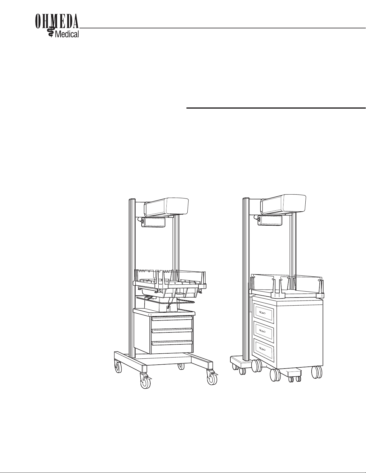
1.1 General ................................................................................................1-1
1.2 SupportStructure.................................................................................1-1
1.3 HeaterAssembly .................................................................................1-1
1.4 ControlUnit..........................................................................................1-1
1.5 BedPlatform ........................................................................................1-2
1.6 Bassinet ..............................................................................................1-2
1.7 Accessories.........................................................................................1-2
2/Setup and Checkout Procedure
2.1 Setup ...................................................................................................2-1
2.2 MechanicalCheckoutProcedure .........................................................2-1
A. OverallAppearance .....................................................................2-1
B. HeaterAssemblyRotation ..........................................................2-2
C. MechanicalChecks.....................................................................2-2
D. Accessory Checks......................................................................2-3
E. Wall Mount Checkout..................................................................2-3
2.3 ControlUnitCheckoutProcedure .........................................................2-4
A. ControlUnitCheck ......................................................................2-4
B. ElapsedTimerCheck ..................................................................2-5
C. ObservationLightCheck .............................................................2-5
D. RaiseandLowerBed SwitchCheck............................................2-5
E. InterlockSwitchCheck................................................................2-6
FPowerFailure,Memory andBatteryTest ....................................2-6
3/Operation
3.1 ControlPanelOperation .......................................................................3-1
A. Displays ......................................................................................3-1
B. IndicatorLights............................................................................3-2
C. Switches .....................................................................................3-2
D. Alarms ........................................................................................3-4
3.2 Preheat,ManualandServoModeOperation ........................................3-7
3.3 ElapsedTimerOperation....................................................................3-11
3.4 BedPlatformOperation......................................................................3-11
3.5 SidePanelOperation .........................................................................3-12
3.6 OxygenAdministration.......................................................................3-13
3.7 GasCylinderInstallationandOperation .............................................3-14
3.8 MountingAccessories .......................................................................3-16
6600−0371−000−DWG 100 MANUAL−DOC, User Reference Manual, OM Panda, English−default
Reproduced from the electronic master in MATRIX