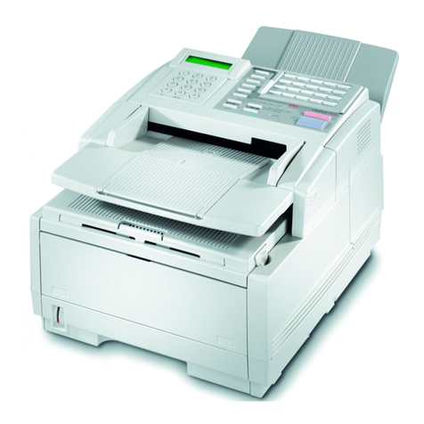
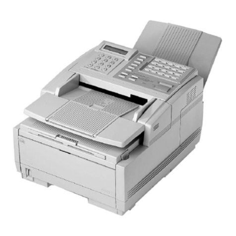
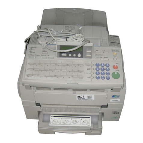
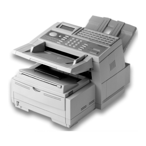
Oki OKIOFFICE 120 User manual

U.K. version 1.0 (15 April 1998). All specifications are subject to change without notice.
OKIOFFICE 120
Facsimile System
Maintenance Manual
¡

i
Table of Contents
Section1 General Description .................................................1-1
1.1 Product Description ..............................................................................................................................1-1
1.2 Applied regulations in North America ...................................................................................................1-2
1.3 Specifications........................................................................................................................................1-2
1.3.1 General specifications...................................................................................................................1-2
1.3.2 Scanning specifications.................................................................................................................1-3
1.3.3 Printer specifications.....................................................................................................................1-4
1.3.4 Memory specifications...................................................................................................................1-4
1.3.5 G3 modem section........................................................................................................................1-5
1.4. Features and Functions.......................................................................................................................1-6
1.4.1 Dialer.............................................................................................................................................1-6
1.4.2 Fax Transmitting............................................................................................................................1-6
1.4.3 Fax Receiving................................................................................................................................1-7
1.4.4 Polling............................................................................................................................................1-7
1.4.5 Copy..............................................................................................................................................1-8
1.4.6 Other features ...............................................................................................................................1-8
1.4.7 Reports..........................................................................................................................................1-8
1.5. Supply Yields.......................................................................................................................................1-9
1.6 Option...................................................................................................................................................1-9
1.7 Dimensions.........................................................................................................................................1-10
1.8 Keypad layout.....................................................................................................................................1-11
1.9 Front view...........................................................................................................................................1-14
1.10 Rear view..........................................................................................................................................1-15
1.11 ID Label Specification.......................................................................................................................1-16
1.12 Labels location..................................................................................................................................1-16
Section2 Machine Composition ..............................................2-1
2.1 Interconnect Block Diagram .................................................................................................................2-1
2.2 Main Control PCB.................................................................................................................................2-3
2.3 NCU PCB..............................................................................................................................................2-5
2.4 Power Supply Unit (PSU) .....................................................................................................................2-6
2.5 Sensors.................................................................................................................................................2-7
2.5.1 Sensor Locations...........................................................................................................................2-7
2.5.2 Sensor Descriptions......................................................................................................................2-7
2.6 Document Scanning Sequence............................................................................................................2-9
2.6.1 Document Detection......................................................................................................................2-9
2.6.2 Document Separation....................................................................................................................2-9
2.6.3 Document Transport......................................................................................................................2-9
2.6.4 Document Scanning......................................................................................................................2-9
2.6.5 Document Discharge...................................................................................................................2-10
2.7 Recording Section ..............................................................................................................................2-11
2.7.1 Recording Paper Feed Path........................................................................................................2-11
2.8 Image Processing...............................................................................................................................2-11
2.8.1 Drum Charge...............................................................................................................................2-12
2.8.2 Drum Exposure ...........................................................................................................................2-12
2.8.3 Development...............................................................................................................................2-12
2.8.4 Image Transfer............................................................................................................................2-13
2.8.5 Residual toner distribute..............................................................................................................2-13
2.8.6 Fusing..........................................................................................................................................2-14
2.9 Transmission Control Procedure (G3 Non ECM mode).............................................................2-16
2.10 Transmission Control Procedure (G3 Non ECM mode, polling)...............................................2-17
2.11 Transmission Control Procedure (G3, ECM mode)..................................................................2-18

ii
Section3 Adjustment Procedures...........................................3-1
3.1 Field Service Program Modes ..............................................................................................................3-1
3.2 Machine Parameter Adjustment ...........................................................................................................3-2
3.2.1 Setting the Machine Parameters...................................................................................................3-2
3.2.2 Clearing the Machine Parameters.................................................................................................3-2
Machine Parameter A:0..........................................................................................................................3-3
Machine Parameter A:1..........................................................................................................................3-3
Machine Parameter A:2..........................................................................................................................3-4
Machine Parameter A:3..........................................................................................................................3-5
Machine Parameter A:4..........................................................................................................................3-6
Machine Parameter A:7..........................................................................................................................3-7
Machine Parameter A:8..........................................................................................................................3-7
Machine Parameter B:0..........................................................................................................................3-8
Machine Parameter B:1..........................................................................................................................3-9
Machine Parameter B:2........................................................................................................................3-10
Machine Parameter B:3........................................................................................................................3-10
Machine Parameter B:4........................................................................................................................3-11
Machine Parameter B:5........................................................................................................................3-11
Machine Parameter B:6........................................................................................................................3-12
Machine Parameter B:7........................................................................................................................3-12
Machine Parameter B:8........................................................................................................................3-13
Machine Parameter J:5 ........................................................................................................................3-13
Machine Parameter J:6 ........................................................................................................................3-13
Machine Parameter J:7 ........................................................................................................................3-14
Machine Parameter J:8 ........................................................................................................................3-14
3.3 Memory Switch Adjustment................................................................................................................3-15
3.3.1 Setting the Memory Switches......................................................................................................3-15
3.3.2 Clearing the Memory Switches....................................................................................................3-15
Memory Switch A:0 - Dialer..................................................................................................................3-16
Memory Switch A:1 - Dialer..................................................................................................................3-16
Memory Switch A:5 - Dialer..................................................................................................................3-17
Memory Switch B:0 - Transmission......................................................................................................3-17
Memory Switch B:1 - Transmission......................................................................................................3-18
Memory Switch B:2 - Transmission......................................................................................................3-19
Memory Switch B:3 - Transmission......................................................................................................3-19
Memory Switch B:5 - Transmission......................................................................................................3-20
Memory Switch C:0 - Reception...........................................................................................................3-20
Memory Switch C:1 - Reception...........................................................................................................3-21
Memory Switch D:0 - Reception...........................................................................................................3-22
Memory Switch D:1 - Reception...........................................................................................................3-22
Memory Switch D:2 - Reception...........................................................................................................3-23
Memory Switch D:3 - Reception...........................................................................................................3-23
Memory Switch E:0 - Scanner..............................................................................................................3-24
Memory Switch G:0 - Remote reception ..............................................................................................3-24
Memory Switch G:1 - Remote reception ..............................................................................................3-25
Memory Switch G:2 - Remote reception ..............................................................................................3-26
Memory Switch G:5 - Remote reception ..............................................................................................3-26
Memory Switch H:0 - Operation...........................................................................................................3-27
Memory Switch H:1 - Operation...........................................................................................................3-27
Memory Switch H:2 - Operation...........................................................................................................3-28
3.4 Clear Programmed Data / User Settings............................................................................................3-28
3.5 All RAM Clear.....................................................................................................................................3-29
3.6 Setting Individual Autodialer Attributes...............................................................................................3-29
3.7 Unique Switch Adjustment..................................................................................................................3-32
3.7.1 Setting the Unique Switches .......................................................................................................3-32
Clearing the Unique Switches ..............................................................................................................3-32
Unique Switch A:0 - Dialer ...................................................................................................................3-33
Unique Switch B:0 - Transmission .......................................................................................................3-33
Unique Switch B:6 - Transmission .......................................................................................................3-34
Unique Switch C:0 - Reception ............................................................................................................3-34
Unique Switch C:1 - Reception ............................................................................................................3-35
iii
Unique Switch C:2 - Reception ............................................................................................................3-36
Unique Switch E:0 - Scanner ...............................................................................................................3-36
Unique Switch E:2 - Scanner ...............................................................................................................3-36
Unique Switch E:4 - Scanner ...............................................................................................................3-37
Unique Switch E:5 - Scanner ...............................................................................................................3-38
Unique Switch E:6 - Scanner ...............................................................................................................3-39
Unique Switch E:7 - Scanner ...............................................................................................................3-40
Unique Switch E:8 - Scanner ...............................................................................................................3-41
Unique Switch E:9 - Scanner ...............................................................................................................3-42
Unique Switch F:0 - Printer ..................................................................................................................3-43
Unique Switch F:1 - Printer ..................................................................................................................3-43
Unique Switch F:2 - Printer ..................................................................................................................3-44
Unique Switch F:3 - Printer ..................................................................................................................3-44
Unique Switch F:5 - Printer ..................................................................................................................3-45
Unique Switch F:6 - Printer ..................................................................................................................3-45
Unique Switch G:0 - Remote reception................................................................................................3-47
Unique Switch G:1 - Remote reception................................................................................................3-47
Unique Switch H:0 - Operation.............................................................................................................3-48
Unique Switch H:1 - Operation.............................................................................................................3-48
Unique Switch H:3 - Operation.............................................................................................................3-49
Unique Switch H:4 - Operation.............................................................................................................3-49
3.8 Printer maintenance mode..................................................................................................................3-50
3.9 Print Program Mode List.....................................................................................................................3-51
3.10 Test Modes.......................................................................................................................................3-51
3.10.1 Life Monitor................................................................................................................................3-51
3.10.2 Printer Test................................................................................................................................3-53
3.10.3 Stamp Test................................................................................................................................3-53
3.10.4 Feeder test................................................................................................................................3-54
3.10.5 Set Background Level...............................................................................................................3-54
3.11 Print Machine Parameters, Memory Switch and Unique Switch Settings ........................................3-55
3.12 Factory Functions.............................................................................................................................3-55
3.12.1 Function List..............................................................................................................................3-55
3.12.2 LED Test ...................................................................................................................................3-56
3.12.3 LCD Test...................................................................................................................................3-56
3.12.4 Key Panel Test..........................................................................................................................3-56
3.12.5 SRAM Check.............................................................................................................................3-57
3.12.6 DRAM Check.............................................................................................................................3-58
3.12.7 RTC(real time clock) Test..........................................................................................................3-58
3.13 Line Tests.........................................................................................................................................3-59
3.13.1 Relay Test.................................................................................................................................3-59
3.13.2 Tonal Signal Test ......................................................................................................................3-60
3.13.3 DTMF Output Test.....................................................................................................................3-61
3.14 Mirror Carriage Transfer Mode.........................................................................................................3-61
3.15 Consumable order sheet ..................................................................................................................3-62
3.16 Clear consumable order sheet .........................................................................................................3-63
3.17 User Settings List..............................................................................................................................3-63
3.18 Clear Life Monitor .............................................................................................................................3-63
3.19 DRAM Clear......................................................................................................................................3-64
3.20 JP4, JP5 Battery Backup..................................................................................................................3-64
Section4 Troubleshooting Procedures ..................................4-1
4.1 Troubleshooting Outline........................................................................................................................4-1
4.2 Recording Paper Jam...........................................................................................................................4-2
4.3 Document Feeder Jam.........................................................................................................................4-2
4.4 Document Feeder Multi-feeding or Skew .............................................................................................4-3
4.5 Mirror Carriage Error ............................................................................................................................4-3
4.6 Transmit Error.......................................................................................................................................4-3
4.7 Transmit Black Lines............................................................................................................................4-3
4.8 Cannot transmit ....................................................................................................................................4-4

iv
4.9 Receive Errors......................................................................................................................................4-4
4.10 Will not Auto-Answer ..........................................................................................................................4-4
4.11 Clearing Jammed Paper.....................................................................................................................4-5
If the original document jams .................................................................................................................4-5
To remove the document: ......................................................................................................................4-5
If a printout jams inside your machine....................................................................................................4-6
If a printout jams inside at a paper side cover........................................................................................4-8
4.12. The Image Quality Problems.............................................................................................................4-9
4.12.1 Blank pages.................................................................................................................................4-9
4.12.2 Black pages.................................................................................................................................4-9
4.12.3 Printout too light.........................................................................................................................4-10
4.12.4 Printout too dark........................................................................................................................4-10
4.12.5 Blurred background...................................................................................................................4-10
4.12.6 Uneven print density..................................................................................................................4-11
4.12.7 Irregularities...............................................................................................................................4-11
4.12.8 White (Black) Line .....................................................................................................................4-11
4.12.9 Toner Smudges.........................................................................................................................4-12
4.13 LCD Error Messages........................................................................................................................4-13
LCD error messages (Alphabetic list)...................................................................................................4-13
4.14 Error Codes ......................................................................................................................................4-17
4.15 Service Call Error..............................................................................................................................4-20
4.15.1 Call For Service.........................................................................................................................4-20
4.15.2 Please Call Service...................................................................................................................4-20
4.16 LCD Failure.......................................................................................................................................4-23
4.17 General Power Failure......................................................................................................................4-23
4.18 Cleaning the Unit..............................................................................................................................4-24
Cleaning the Document Feeder Area...................................................................................................4-24
Cleaning the Inside of Contact Glass...................................................................................................4-24
Cleaning the FBS .................................................................................................................................4-25
Cleaning the LED print head. ...............................................................................................................4-25
Section5 Disassemble..............................................................5-1
5.1 Rear cover............................................................................................................................................5-3
5.2 Shielding plate R...................................................................................................................................5-3
5.3 Front cover ...........................................................................................................................................5-4
5.4 Upper right cover..................................................................................................................................5-4
5.5 Book cover............................................................................................................................................5-5
5.6 Upper rear cover...................................................................................................................................5-5
5.7 Upper left cover ....................................................................................................................................5-6
5.8 Upper front cover..................................................................................................................................5-6
5.9 Panel lower cover.................................................................................................................................5-7
5.10 PS fan motor and PS fan motor cover................................................................................................5-8
5.11 Connect A PCB...................................................................................................................................5-9
5.12 NCU PCB............................................................................................................................................5-9
5.13 Main control PCB..............................................................................................................................5-10
5.14 Modem PCB .....................................................................................................................................5-11
5.15 Modular PCB / Connect C PCB........................................................................................................5-11
5.16 Power supply unit .............................................................................................................................5-12
5.17 Power switch assembly ....................................................................................................................5-13
5.18 Duct and Inside fan motor.................................................................................................................5-14
5.19 Cover switch.....................................................................................................................................5-15
5.20 High voltage unit...............................................................................................................................5-16
5.21 Home sensor ....................................................................................................................................5-17
5.22 End sensor........................................................................................................................................5-17
5.23 Gas spring ........................................................................................................................................5-18
5.24 Book scanner glass ..........................................................................................................................5-19
5.25 Book cover pad.................................................................................................................................5-20

v
5.26 ADF contact glass............................................................................................................................5-20
5.27 Tx cover............................................................................................................................................5-21
5.28 ADF assembly..................................................................................................................................5-21
5.29 Guide supporter................................................................................................................................5-23
5.30 Separator roller assembly.................................................................................................................5-24
5.31 Document sensor 2 (DS2)................................................................................................................5-25
5.32 Press roller........................................................................................................................................5-25
5.33 Tx cover release lever......................................................................................................................5-26
5.34 ADF interlock....................................................................................................................................5-26
5.35 Gear cover and Gear........................................................................................................................5-26
5.36 Inner guide B....................................................................................................................................5-28
5.37 Sensors (DA3, DS1, DB4)................................................................................................................5-28
5.38 Exit roller...........................................................................................................................................5-29
5.39 Feed roller assembly/Retard roller assembly...................................................................................5-30
5.40 Outer guide B....................................................................................................................................5-31
5.41 ADF permit sensor (APS).................................................................................................................5-31
5.42 Press roller........................................................................................................................................5-32
5.43 Exit press roller.................................................................................................................................5-32
5.44 Confirmation stamp...........................................................................................................................5-33
5.45 Lock lever shaft................................................................................................................................5-33
5.46 Base frame assembly.......................................................................................................................5-34
5.47 Pickup roller......................................................................................................................................5-35
5.48 ADF motor and FBS motor...............................................................................................................5-36
5.49 Inverter PCB.....................................................................................................................................5-39
5.50 Mirror carriage A and B.....................................................................................................................5-40
5.51 Lamp.................................................................................................................................................5-44
5.52 Mirror A and B...................................................................................................................................5-45
5.53 Control panel PCB 1 and 2...............................................................................................................5-46
5.53 LCD assembly..................................................................................................................................5-47
5.54 Connect B PCB.................................................................................................................................5-47
5.55 Speaker............................................................................................................................................5-48
5.56 Rear cover B.....................................................................................................................................5-48
5.57 PES sensor.......................................................................................................................................5-49
5.58 PES sensor (optional paper supply unit)..........................................................................................5-50
5.59 Solenoid of optional paper supply unit..............................................................................................5-51
5.60 Right cover........................................................................................................................................5-52
5.61 HPES sensor / RCIL sensor.............................................................................................................5-53
5.62 PSS sensor / TOS sensor................................................................................................................5-54
5.63 Transfer roller...................................................................................................................................5-55
5.64 Lock lever.........................................................................................................................................5-55
5.65 LED print head..................................................................................................................................5-56
5.66 Paper guide......................................................................................................................................5-57
5.67 PDS sensor.......................................................................................................................................5-57
5.68 Fuser unit..........................................................................................................................................5-58
5.69 Feed roller B.....................................................................................................................................5-59
5.70 Feed roller C.....................................................................................................................................5-61
5.71 Solenoid............................................................................................................................................5-61
5.72 RX motor...........................................................................................................................................5-63
5.73 Cassette PCB...................................................................................................................................5-64
5.74 Cassette rail......................................................................................................................................5-66
5.75 Cassette PCB / Connect PCB..........................................................................................................5-67
1998

vi

1-1
Section1
General Description
1.1 Product Description
The OKIOFFICE 120 is a Multi-function product with flat bed scanner and Group 3 facsimile machine.
Documents are printed on plain paper using dry electrophotographic printing.

1-2
1.2 Applied regulations
1) EMI
EN55022, EN50081-1, EN50082-1
2) Safety
EN41003, EN60950
3) PTT
NTR-3
4) EPA (United States Environmental Protection Agency)
ENERGY STAR
1.3 Specifications
1.3.1 General specifications
Item Specifications / Comments
Type Multi-function product with flatbed scanner & high-speed facsimile
transmitter and receiver
Telephone network PSTN (Public Switched Telephone Network) or equivalent
Compatibility ITU-T Group 3
Transmission control
protocol ITU-T T.4 and T.30
Coding ITU-T-standard MH, MR and MMR, proprietary MSE
Communication method Half-duplex per ITU-T V.17, V.33, V.29, V.27ter and V.21
Modem 14400, 12000, 9600, 7200, 4800 and 2400 bps with automatic
fallback per ITU-T, V.17, V33, V.29, V.27ter and V21.
Control signal speed is 300 bps.
ITU-T sub-address /
password Supported
Triple Access Allows up to three simultaneous operations
Display LCD: 2 lines, 20 characters per line
Scanning method Flatbed CCD
Recording method Dry, electrophotographic (LED) process
Scanning width 208 mm / 252 mm / 294 mm
Recording width 206 mm / 251 mm
Acceptable document size ADF (Auto Document Feeder) section
Single sheet Two or more sheets
Max: 306 mm (W) ×900 mm (L)Max: 297 mm (W) ×420 mm (L)
Min: 120 mm (W) ×100 mm (L)Min: 148 mm (W) ×105 mm (L)
Document thickness
52.3 --104.7g/m2
FBS (Flatbed Scanner) section
Max: 257 mm (W) ×364 mm (L)
Recording paper Paper cassette:
B4/A4/B5R/A5R; 400-sheets capacity
Optional paper cassette:
B4/A4/B5R/A5R; 200-sheets capacity
Multipurpose Tray:
A4 / A5 / A5R / B5; 1 sheet capacity
Document Memory 2 MB (upgrade option: plus 2MB or plus 4MB or plus 8MB)
Error Correction Mode
(ECM) Transmit and receive
Buffer capacity: 64KB

1-3
Item Specifications / Comments
Environmental conditions Ambient temperature: 10°Cto 32°C(50 to 89.6 degrees F)
Relative humidity: 20 % to 80 % with no condensation
Power requirements 230 VAC ±10 %; 50/60 Hz
Power consumption Standby: 21 W
Transmit: 47 W
Receive: 592 W
Copy: 621 W
Maximum: 839 W
(Simultaneous copying, communicating and scanning)
Weight 32 Kg (70.4 pounds) Weight includes trays, drum , toner cartridge.
1.3.2 Scanning specifications
Item Spcifications / Comments
Scanning method Flatbed CCD
Scanning width ADF (Automatic document feeder) section
208 mm / 252 mm / 294 mm
FBS (Flatbed scanner) section
208 / 252 mm
Acceptable document size ADF (Auto document feeder) section
Single sheet Two or more sheets
Max: 306 mm (W) ×900 mm (L) Max: 297 mm (W) ×420 mm
(L)
Min: 120 mm (W) ×100 mm (L) Min: 148 mm (W) ×105 mm
(L)
Document thickness
52.3--104.7g/m2
FBS (Flatbed scanner) section
Max: 257 mm (W) ×364 mm (L)
Min: No limit
Document size auto-
detection ADF section: A4/B4/A3
FBS section: N/A
Scanning resolution (Fax) Horizontal ×Vertical
Normal: 8 dots ×3.85 lines (/mm) (203 dpi ×98 dpi)
Fine: 8 dots ×7.7 lines (/mm) (203 dpi ×196 dpi)
Super fine: 8 dots ×15.4 line (/mm) (203 dpi ×392 dpi)
Grayscale: 8 dots ×7.7 line (/mm) (203 dpi ×196 dpi)
If the remote unit has 400 ×400 dpi print ability:
Super fine: 16 dots ×15.4 line (/mm) (406 dpi ×392 dpi)
Grayscale: 16 dots ×15.4 line (/mm) (406 dpi ×392 dpi)
Scanning resolution (Copy) Horizontal ×Vertical
Normal: N/A
Fine: N/A
Super fine: 16 dots ×15.4 line (/mm) (406 dpi ×392 dpi)
Grayscale: 16 dots ×15.4 line (/mm) (406 dpi ×392 dpi)
Document scan time (Fax) Normal: 2 sec/page
Fine: 4 sec/page
Super fine: 8 sec/page
Grayscale: 4 sec/page, when copying, 8 sec/pages
(Based on ITU-T test document No.1)
Document scan time (Copy) Super fine: 8 sec/page
Grayscale: 8 sec/page
(Based on ITU-T test document No.1)
Automatic document feeder
capacity A4 : 50 sheets
B4 : 25 sheets
A3 : 15 sheets

1-4
Item Spcifications / Comments
Grayscale (Fax) 64 level.
(128 level: only when using the non-memory transmission and the
remote unit has 400 ×400 dpi print ability.)
Grayscale (Copy) 128 level.
Document contrast 5 levels (Manual adjustment)
Original document feeding
direction ADF section: Face up
FBS section : Face down
1.3.3 Printer specifications
Item Specifications / Comments
Printing method Electrophotographics (LED) printer by one-component nonmagnetic
toner
Print width A4:206 mm / B4: 251 mm
Printer Resolution Horizontal: 16 dot/mm (406 dpi)
Vertical: 15.4 line/mm (392 lpi)
Print speed 12 ppm (A4-portrait)
Receive paper tray capacity 150 sheets
Recording paper
specifications B4: (257 mm (W) ×364 mm (L))
B5R: (257 mm (W) ×182 mm (L))
A4: (210 mm (W) ×297 mm (L))
A5R: (210 mm (W) ×146 mm (L))
Paper cassette capacity Paper cassette: 400 sheets +200 sheets (option) + 200 sheets
(option)
Multipurpose tray: 1 sheet
Toner yield Approx. 6000 pages
Based on A4-sized sheets, 5% document coverage and continuous
printing.
Drum yield Approx. 10000 pages
Printer warm up time Under 40 second
1.3.4 Memory specifications
Item Specifications / Comments
Document memory 2 MB
Optional memory upgrade: 2 MB, 4 MB or 8MB
Out-of paper reception Receives up to 100 communications to memory if recording paper
supply or printer supplies are empty.
Document stored capacity 2 MB: 158 pages
4 MB: 318 pages
6 MB: 478 pages
10 MB: 798 pages
Document memory backup 2 MB: 100 hours after turning on for 24 hours.
4 MB: 50 hours after turning on for 24 hours.
6 MB: 30 hours after turning on for 24 hours.
10 MB: 20 hours after turning on for 24 hours.
Memory usage indication On the LCD

1-5
1.3.5 G3 modem section
Transmission mode V.17 V.33
Modulation method 128 Pt.
TCM 64 Pt. TCM 32 Pt. TCM 16 Pt. TCM 128 Pt.
TCM 64 Pt. TCM
Transmission speed
(bit/s) 14400 12000 9600 7200 14400 12000
Modulation speed
(baud) 2400 2400 2400 2400 2400 2400
Carrier frequency (Hz) 1800
Detection method Synchronism
Automatic equalizer Automatic adaptive equalizer
Transmission mode V.29 V.27ter V.21
Modulation method 16 Pt. QAM 8 Pt. QAM 8 Pt. PhM 4 Pt. PhM FSK
Transmission speed
(bit/s) 9600 7200 4800 2400 300
Modulation speed
(baud) 2400 2400 1600 1200 300
Carrier frequency (Hz) 1700 1800 f (0) = 1850
f (1) = 1650
Detection method Synchronism FS
Automatic equalizer Automatic adaptive equalizer None

1-6
1.4. Features and Functions
1.4.1 Dialer
Item Specifications / Comments
Autodialer 200 total; 128 speed dial, 72 one-touch(8 programmable one-touch)
(Up to 40 digits per location; 24 characters per location ID)
Telephone index Select autodialer entries in LCD by Location ID name.
Type of dialing Tone or pulse(10 pps)
Dialing pause time 5-10 second.
On-hook dialing Available
Redial Auto redial in fax mode, programmable for 2 to 5 attempts at 3, 4, or
5 minute intervals; manual last-number redial.
PIN access Available
1.4.2 Fax Transmitting
Item Specifications / Comments
Transmit Terminal Identifier
(TTI) Alphanumeric or symbol, up to 22 characters
Subscriber ID Numeric, up to 20 characters
Memory transmission Available.
Non-memory transmission Available. (ADF only.)
Delayed transmission Programmable up to 31 days in advance
Broadcast transmit Up to 220 locations.
Relay broadcast Initiation up to 220 locations and hub abilities up to 10 groups
SecureMail Transmit and receive (10 mailboxes for receiving, 4 digits ID-code).
SecureMail
(ITU-T subaddress /
password)
Transmit and receive (50 mailboxes for receiving, 4 digits passcode).
Group communication Allows multiple broadcast or polling locations to be placed in up to 32
call groups. Up to 200 locations can be placed in a group. Group 0
includes all autodialer locations.
Security transmission Compares the last 4 numbers of the dialed fax number to the last 4
digits of the subscriber ID.
Batch transmission 5 boxes with a location ID of 24 characters. 40 files per box.
Programmable up to 24 hours per box.
Numbering pages Just before sending a fax, you can set your fax machine to number
each page in order. This will help the recipient keep track of all the
pages.
Cover page Cover page shows date and time, sender’s name and fax number,
and a 40-character user-programmable message.
Delayed commands Store up to 99 delayed commands.
Department code For tracking transmissions by department.
Hold up to 100 department codes.
Call request During sending or receiving, a voice conversation can be initiated on
the same call after each page is printed.
(Works only if the optional handset is attached.)

1-7
1.4.3 Fax Receiving
Item Specifications / Comments
Receive mode Fax ready, Tel/Fax Ready, Fax/Tel Ready, Ans/Fax Ready or
Tel ready mode; user selectable.
Distinctive ring detection Ability to answer on specific ring patterns. User selectable
Number of rings In Fax ready mode, select 1 to 9 rings.
Automatic reduction Automatically reduces incoming documents to fit on receive paper.
Receive reduction rate
(Auto) Auto: 50 % to 100 % when auto reduction is selected.
Reduction margin: 0-85 mm (Initial value: 24 mm)
Receive reduction rate
(Fixed value) 100, 97, 91, 81, 75 % :User selectable
Half-page reception Available.
(This feature tells the machine to combine two of half-page
receptions onto a single sheet.)
SecureMail 10 mailboxes for receiving, 4 digits ID-code.
Holds a SecureMail up to 31 days.
SecureMail
(ITU-T subaddress /
password)
Using the ITU-T sub-address and password provide to SecureMail
communication not only with other OKIOFFICE 120 fax machines (or
compatible brand), but fax machines of other manufactures as well.
Up to 50 mailboxes for receiving, 4 digits passcode.
Holds a document up to 31 days (or no limit).
Block junk fax Ability to reject “junk fax” receptions: user selectable three options.
Closed network Proprietary network option
Out-of paper reception Receives up to 100 communications to memory if recording paper
supply or printer supplies are empty.
Security reception You can tell the machine to keep all received faxes in memory (but
not print them) after a certain time; then, later, you instruct it to go
ahead and print out the saved faxes.
Remote reception upon
second phone connection Fax is activated upon termination of a call that is answered by a
telephone connected to second phone jack.
1.4.4 Polling
Item Specifications / Comments
Delayed polling Programmable up to 31 days in advance.
Regular polling Retrieves a document from the remote fax machine.
Continuous polling Retrieves continuously a document from any remote fax machine for
the designed time.
Database polling Possible only in communication with certain memory equipped
OKI fax machine.
Retrieves a document stored as a file in the remote fax machine’s
memory.
You can enter as many as 10 file numbers in one operation.
Enter 4 digits file number.
Database polling
(ITU-T subaddress
/password)
Using the ITU-T sub-address and password provide to database
polling communication not only with other OKIOFFICE 120 fax machines
(or compatible brand), but fax machines of other manufactures as well.
Retrieves a document stored in a memory-box in the remote fax
machine.
You must enter a ITU-T subaddress to retrieves a document from
any remote fax’s memory box.

1-8
1.4.5 Copy
Item Specifications / Comments
Multiple copies Up to 99 with sorting
Copy reduction and
enlargement rate 50 % to 200 % at 1 % interval.
Copy reduction rate Fixed value: 115, 122, 141, 172, 200%
Copy enlargement rate Fixed value: 50, 70, 81, 86%
Copy protect Available
1.4.6 Other features
Item Specifications / Comments
Silent operation Available
Audible alarm Available
Operation protect Available
Second telephone jack Available
Transmission confirmation
stamp If you set, it will automatically place a small stamp mark on the front
of each original document that it successfully scans.
1.4.7 Reports
Report Description
Function list Prints a program mode list showing user programming tree.
One-touch dial list Prints numbers stored in the one-touch keys.
Speed dial list Prints phone numbers stored in speed dial locations.
Programmable one-touch
list Prints numbers stored in programmable one-touch keys.
User settings list Prints current machine settings as programmed by the user.
Group number list Prints groups stored in the autodialer.
Delayed command list Prints the delayed commands.
SecureMail box list SecureMail boxes with owners’ names.
SecureMail reception
message Notifies mailbox owners of SecureMail receptions.
Confirmation report Transmit Confirmation Report (TCR) or Receive Confirmation Report
(RCR); User selectable on/off.
Activity journal Prints a cumulative total of the last about 125 transmissions and/or
receptions; user selectable as manual or automatic.
Cover page Transmit cover page showing date, receiver’s and sender’s names,
and a 40-character user-programmable message.
Batch transmission box list Batch transmission boxes stored remote fax number and transmit
starting time.
Batch transmission file list Print the files number list of documents stored in the batch
transmission box.
F-code box list List of F-code boxes stored in fax machine.
F-code reception message Notifies of F-code box receptions.
F-code box file list Print the box and files number list of documents stored in the F-code
box.
Supplies order sheet The order sheet print automatically, when the toner or drum cartridge
must be replace.
Junk mail protect list List of receiving block number.
Power failure report Prints if any documents in memory were erased due to power failure.
Check message Prints if communication error occurs; accompanied by audible alarm.
T.30 monitor list Available

1-9
1.5. Supply Yields
Item Specifications / Comments
Drum cartridge 10000 pages
Toner cartridge 6000 pages Based on A4-sized sheets, 5 % document coverage
and continuos printing.
Transfer roller 30000 pages
Fuser unit 60000 pages
Stamp 30000 times
1.6 Option
Item Specifications / Comments
Paper supply unit A4 / A5 / A5R / B5; 200 sheets capacity
Handset Mark IV
Upgrade Memory Plus 2 MB, Plus 4MB or Plus 8MB
RS-232C interface Kit Class 1
Second phone line kit AL-100
Printer Controller Kit WP-100
Scramble Kit DS-100

1-10
1.7 Dimensions
Dimension in mm

1-11
1.8 Keypad layout
Here is a brief description of the keys on your fax machine and what they do, as well as a look at your
machine’s indicator lights and their meanings.
1. STAMP light — If glowing, indicates the transmission confirmation stamp feature (see page 2.6) is
on.
2. AUTO ANSWER light — You can select which mode your fax machine uses to handle incoming calls:
answering automatically as a fax machine (Fax Ready mode) or waiting for the user to pick up the
optional handset (Tel Ready mode). If the AUTO ANSWER light is glowing, your fax machine is in
auto-answer mode.
3. MEMORY RECEIVE light — If glowing, indicates your fax machine is receiving an incoming fax
document into the machine’s electronic memory.
4. COMMUNICATION light — If glowing, advises you the fax machine is performing communication.
5. REVIEW COMMANDS — Press to review or alter pending fax commands.
6. MONITOR/CALL — During on-hook dialling, turns the monitor speaker off or on. When you’re sending
a fax, activates the call request feature.
7. ALARM light — If glowing, indicates a problem has occurred during fax communication or your fax
machine encounters a problem printing a fax or copy. Check the display or an error report for more
information.
8. PAPER JAM light — Glows when a printout (received fax message or copy) becomes jammed in
your fax machine.
9. REPLACE PAPER light — Glows when the paper cassette is empty. See page 1.16 for more details
on replacing paper.
10.GROUP DIAL — Helps you set up a fax transmission to a call group, a set of fax numbers which will
receive the same document in one fax operation.
11.COMMUNICATION OPTIONS — Chooses from among several fax options: delayed transmission,
SecureMail transmission, relay broadcast, polling, batch transmission or F-Code communication.
12.BROADCAST — Helps you set up the process of a fax broadcast (sending the same document to
more than one location).
13.Numeric keypad — Just like the numeric keys on a regular tone-dialling phone. In addition to
dialling phone and fax numbers, they also enter numbers when you’re making certain settings.
14.START — Begins a manual fax transmission, manual reception or copying.
15.CLEAR ALL — Resets copying settings to their defaults.
16.STOP — An all-purpose STOP key. Stops the current operation, ejects a document from the
automatic document feeder and cancels alarms.

1-12
17.SPEED DIAL/TEL INDEX— Starts a speed-dialling operation, which you finish by pushing three of the
keys on the numeric keypad. Also displays one-touch and speed dial entries sorted
alphanumerically, as in a telephone directory.
18.BOOK DOC SIZE — Sets the fax for either A4-, B4-, A5R- or B5R-sized documents when you use
the flatbed scanner.
19.MEMORY TRANSMIT — Selects which transmission mode your fax uses, whether from memory or
from the document feeder. If the light next to this key is glowing, your fax will scan documents
into memory before trying to send them. Otherwise, your fax will transmit straight from the feeder,
which is slower and also prevents others in your office from using the fax until your communication
is absolutely complete. (When you use the flatbed scanner, the machine always uses memory
transmission).
20.CANCEL — Press this key to delete characters on the LCD and cancel commands you have entered
into the machine.
21.In Fax mode:
REDIAL/PAUSE — Redials the last number you dialled. In certain operations, it also produces a
special pause character which can be useful during the dialling of long-distance numbers.
Or, in Copy mode:
PAPER SIZE ?— Selects the printout paper you want to use.
22.ENTER — Much as STOP is a “Whoa!” key, ENTER is a “Go!” key.
It confirms user settings, begins operations and moves through
command levels.
23.In Fax mode:
DIALLING OPTIONS — Press this to insert special symbols into telephone numbers (see page 2.7).
Or, in Copy mode:
SORT COPY — Press this key to toggle the sorting of printed copies.
24.In Fax mode:
/PROGRAM — Scrolls (moves) through features and command options as displayed on the LCD.
Or, in Copy mode:
Press to increase the reduction or enlargement rate at 1% intervals.
25.In Fax mode:
FLASH — Lets you quickly disconnect a call and go right to the next one without having to hang up
the handset.
Or, in Copy mode:
ENLARGE % — Press this key to choose one of several fixed copy enlargement rates. (See page
1.37 for more information.)
26.In Fax mode:
— Scrolls (moves) through features and command options as displayed on the LCD.
In Fax mode, while scanning a document:
NEXT — Press to tell your machine to scan one or more additional documents after the current
scanning ends.
In Copy mode:
Press to decrease the reduction or enlargement rate at 1% interval.
27.In Fax mode:
Blue key — Press to access the other telephone networks such as Cable & Wireless (Mercury).
Or, in Copy mode:
REDUCT % — Press this key to choose one of several pre-set copy reduction rates. (See page
1.37 for more information.)
28.RESOLUTION —
In Fax mode:
Press to toggle among the three resolution modes and 64-level greyscale.
In Copy mode:
Press to select either superfine or 128-level greyscale mode.
29.CONTRAST — Press to enter the contrast setting mode. To change the contrast level, press or
keys.
30.COPY/FAX — Press this key to toggle between Fax mode or Copy mode.

1-13
31.One-Touch Keys — The keys labelled 01-40 (or 41-80, if you’re using fliptab B) offer one-touch
dialling convenience. You also can use the keys labelled 73-80, if you’re using fliptab B, for
programmable functions: this lets you teach your machine an advanced multi-step function just
once, then recall the function at any time by pressing one of these keys.
Table of contents
Other Oki Fax Machine manuals