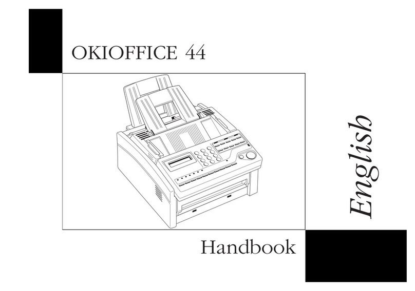
Oki TF-300P Quick start guide

I
TF-300P
Field Service Manual
Ver. 02
July 8, 1999
TTIC

II
Index
1. INTRODUCTION 1-1
1.1 STANDARD SPECIFICATIONS 1-1
1.2 GENERAL USER FUNCTION 1-6
1.3 GENERAL APPEARANCE 1-7
1.3.1 APPEARANCE 1-7
1.3.2 SHOW THE OPERATION PANEL 1-7
1.4 GENERAL MAINTENANCE FUNCTION 1-8
2. INSTALLATIONS 1-1
2.1 GENERAL 1-1
2.2 SITE SELECTION 1-2
2.3 UNPACKING 1-2
2.4 CHECK OF CONTENTS 1-3
2.5 INSTALLATION OF ATTACHMENTS 1-3
2.5.1 CARTRIDGE AND SIM CARD 1-3
2.5.2 HANDSET AND LINE CORD 1-3
2.5.3 AC CORD CONNECTION 1-4
2.5.4 LOADING PAPER 1-5
3. MAINTENANCE 3-1
3.1 ROUTINE INSPECTION 3-1
4. SYSTEM TEST 4-1
5. MECHANICAL DISASSEMBLY AND REASSEMBLY 5-1
5.1 GENERAL 5-1
5.1.1 PRECAUTIONS PARTS REPLACEMENT 5-1
5.1.2 TOOLS 5-1
5.2 GENERAL MECHANICAL STRUCTURE 5-2
5.3 HOW TO DISASSEMBLE AND REASSEMBLE 5-3
5.3.1 INSTALLING THE INK CARTRIDGE AND SIM CARD 5-3
5.3.2 AC PLUG, HANDSET AND DOC. SUPPORT 5-3
5.3.3 BOTTOM PLATE UNIT 5-3
5.3.4 SIM CARD HOLDER ASSEMBLY 5-4
5.3.5 SCANNER MODE UNIT 5-4

III
5.3.6 SCANNER MODE ASM.5-5
5.3.7 SCANNER UNIT 5-5
5.3.8 LOWER FRAME UNIT 5-5
5.3.9 UPPER FRAME UNIT.5-6
5.3.10 DOCUMENT GUIDE ASSEMBLY 5-7
5.3.11 OPERATION PANEL UNIT 5-7
5.3.12 UPPER COVER UNIT 5-8
5.3.13 PRINTER MODE UNIT 5-8
5.3.14 PRINTER MODE ASM.5-8
5.3.15 PAPER FEEDER UNIT 5-9
5.3.16 BASE FRAME UNIT 5-10
5.3.17 BOTTOM COVER UNIT 5-11
6. CIRCUIT DESCRIPTION 6-1
6.1 MAIN BOARD CIRCUIT 6-1
6.1.1 BLOCK DIAGRAM 6-1
6.1.2 INTEGRATED FAX CONTROLLER 6-1
6.1.3 SCANNER CONTROLLER 6-11
6.1.4 MOTOR DRIVERS 6-11
6.1.5 SWITCH AND SENSORS 6-11
6.1.6 BATTERY AND POWER DOWN RESET 6-11
6.1.7 FAX MODEM CIRCUIT 6-11
6.1.8 MEMORY 6-16
6.1.9 NETWORK INTERFACE 6-16
6.1.10 PANEL INTERFACE 6-16
6.2 PRINTER BOARD CIRCUIT DESCRIPTION 6-16
6.2.1 PRINTER BOARD TO INKJET HEAD INTERFACE 6-16
6.2.2 PAPER & CARRIAGE MOTOR 6-16
6.2.3 SENSORS & HOST CONNECTOR 6-16
6.2.4 PRINTER HEAD SUPPLY DETECT 6-16
6.2.5 MICROPROCESSOR AND MEMORY 6-16
6.3 KEY BOARD CIRCUIT DESCRIPTION 6-17
6.4 SIMCRAD BOARD CIRCUIT DESCRIPTION 6-17
6.5 NCU CIRCUIT DIAGRAM DESCRIPTION 6-17
6.5.1 GENERAL FUNCTIONS OF NCU (NETWORK CONTROL UNIT) CIRCUIT 6-17
6.5.2 DIALLING METHOD 6-17
6.5.3 RINGING DETECTION 6-18
6.5.4 FAX MESSAGE RECEIVING 6-18
IV
6.5.5 FAX MESSAGE TRANSMITTING 6-18
6.5.6 BUILT-IN HANDSET AND SERIAL EQUIPMENT DETECTION 6-18
6.6 TELEPHONE CIRCUIT DIAGRAM DESCRIPTION 6-18
6.6.1 GENERAL FUNCTIONS OF TELEPHONE CIRCUIT 6-18
6.6.2 TELEPHONE IC AS2534 GENERAL DESCRIPTION 6-18
6.6.3 RINGING 6-19
6.6.4 DTMF DIALLING 6-19
6.6.5 PULSE DIALLING 6-19
6.6.6 SPEECH MODE 6-19
6.7 POWER SUPPLY DESCRIPTION 6-20
6.7.1 INPUT SPECIFICATION 6-20
6.7.2 OUTPUT SPECIFICATION 6-20
6.7.3 GENERAL FEATURE 6-21
6.7.4 ENVIRONMENT SPECIFICATION 6-21
6.7.5 INTERNATIONAL STANDARDS 6-22
7. TROUBLESHOOTING 7-1
7.1 LCD FAILS TO DISPLAY AFTER POWER ON7-1
7.2 HALF OF LCD DISPLAY FULL BLACK AFTER POWER ON7-2
7.3 LCD DISPLAY NORMAL ON STARTING BUT KEY FAILED 7-3
7.4 TIME DISPLAY ABNORMAL 7-4
7.5 IT WORKS PRESSING KEY BUT SPEAKER REMAINS MUTE 7-5
7.6 RESET ON STARTING 7-6
7.7 LCD DISPLAY “NO PAPER”WHILE RECORDING PAPER IS LOADED 7-7
7.8 C.I.S. MOTOR REMAINS MOTIONLESS 7-8
7.9 FAILED TO FEED DOCUMENT 7-9
7.10 OVER FEEDING DOCUMENT UNTIL “DOCUMENT JAM”7-9
7.11 COPY QUALITY IS TOO BRIGHT 7-10
7.12 FAILED TO TRANSMIT SUCCESSFULLY 7-10
7.13 FAILED TO RECEIVE SUCCESSFULLY 7-11
7.14 PRINTER ENGINE OFF 7-11
7.15 PRINTER ACTS FAILED 7-12
7.16 CERTAIN BLOCKS FAILED IN PRINTING 7-12
7.17 COPY ALL BLACK 7-13
7.18 ALL WHITE PRINTING 7-14
7.19 PRINTING OR COPYING ERROR DATA 7-14
7.20 PRINTER CAN’T INITIAL 7-15
7.21 CARRIAGE MOTOR REMAINS MOTIONLESS 7-16

V
7.22 LINE FEED MOTOR REMAINS MOTIONLESS 7-17
7.23 PRINTING WITH LINE LOST 7-17
7.24 SIMCARD INVALID 7-18
7.25 TROUBLE SHOOTING FAX MECHANICAL PROBLEM 7-19
7.26 NCU/TEL BOARD TROUBLE SHOOTING 7-22
7.26.1 RINGING 7-22
7.26.2 DIALLING 7-22
7.26.3 HANDSET FUNCTION 7-22
8. PART LIST 8-1
8.1 MAIN BOARD PART LIST 8-1
8.2 KEY BOARD PART LIST 8-4
8.3 PRINT BOARD PART LIST 8-5
8.4 SIMCARD BOARD PART LIST 8-6
8.5 NCU BOARD PART LIST 8-6
8.6 POWER SUPPLY PART LIST 8-13
9. MECHENICAL DRAWING AND PARTS LIST 9-1
10. CIRCUIT DRAWING 10-1

1-1
1. INTRODUCTION
1.1 Standard Specifications
ITEM SPECFICATION
1. General
(1) Type Desk Top Transceiver
Copier
(2) Line PSTN or PABX
(3) Compatibility ITU-T G3
(4) Communication Time Depends on What FAX Engine is selected
Controller Modem
Coding method
Time
FC-200 R96DFXL MH: ECM OFF
ECM ON
18 sec
12 sec
FC-200M
(Option)
R144EFXL MR: ECM OFF
ECM ON
10~12 sec
8sec
(5) LCD 1 × 16
(6) Key Number 32
CCITT key×12 Start Key×1 Stop×1
Function key×1 Redial / Pause×1 Receive Mode key×1
On Hook key×1 One-touch×9 Directory×1
Resolution×1 Recall/Access×1 Cursor×2 (←→)
(7) LED Number 3 (Alarm, Memory, Hook)
(8) Auto Dial Alpha-Search, One-touch, Redial
(9) Automatic Reception Yes
(10) Coding MH/MR/MMR (Option)
(11) ECM User setting for the ON/OFF selection (Option)
(12) Polling Free / Password
(13) Timer Transmission When there are any transmission files pending in memory, no more
timer transmission can be reserved. (24hrs)
(14) Multi-Copy Up to 50
(15) TTI Inside/Off Date/Time/ID/Name/Page
(16) Languages 3, Any combination
(17) TAD Interface Yes (CNG detection in idle mode)
(18) Buitl-inTAM Only for TF-300PT
(19) SIM CARD Interface Yes
(20) Distinctive Ringing Yes
(21) Parallel Fax pick-up Yes
(22) Caller ID (Option)
2. Scanner Section
(1) Scanning Method CIS

1-2
ITEM SPECFICATION
(2) ADF 5 pages (Multi 0.07-0.12 mm / Single 0.06-0.15 mm)
(3) Document A4/Letter
Min. Length 200 mm / Max. Length 600 mm
(4) Resolution Horizontal: 8 dots/mm
Vertical: 7.7 (Photo) l/mm
Vertical: 3.85 (Std), 7.7 (Fine) l/mm
(5) Grey Scale 64 Levels (Error Diffusion)
(6) Auto Background Control Yes
(7) Contrast Light/Normal/Dark (User Selectable)
LIGHT for dark original
DARK for Light original
(8) Document Orientation Face down
(9) Effective Scan Width 210mm
(10) Scanning Speed 20 ms/line
3. Printer Section
(1) Printer Method Ink-jet (HP solution)
(2) Paper Orientation Face Up Print
(3) Resolution 300dpi × 200dpi (Vertical5Horizontal)
(4) Recording Paper Pre-cut Plain Paper (A4 / Letter)
(5) Paper Width 216 mm (max)
(6) Recording Width 203 mm
(7) Printable Area Top –4mm/Bottom –7mm /Left and Right side –3mm
(8) Paper Cassette 50 sheets (90g A4)
(9) Inkjet Cartridge 1700 pages (ITU Chart #1) (40cc Pen Cartridge)
850 pages (ITU Chart #1) (20cc Pen Cartridge)
(10) Printing Speed 2 pages/min
(11) Reduction Selectable for user (100, 94, 86, 79%)
(12) Print Density OD 1.2 ¡Ó0.2
4. Dialling
(1) Alpha Dialling 20 Locations (40 digit numbers / 20 char. Tel + Fax NR)
W/doc. or polling operationàFax number to be chosen.
W/O doc. and “non-polling”operationàTel number to be chosen.
(2) One Touch 9 Locations
(3) Group Dialling No
(4) Manual Redial Last No. Dialled

1-3
ITEM SPECFICATION
(5) Automatic Redial Redial Countàselectable by the service parameter (1 to 9)
Redial Interval àselectable by the service parameter (1 to 5min)
Redial Conditionàbusy tone detection
(6) Dialling DTMF(Pulse Optional)
(7) PABX-> PSTN Access YES (Digit / Flash) (Earth optional)
5. Telephone Features
(1) Built-in Handset Yes
(2) Monitor Speaker Yes
(3) Handsfree Talking No
(4) On-Hook Dialling Yes
(5) Volume Control On-line adjustment (4 levels), automatically fallback to default
value when the call is finished. (Speaker and internal ring signal)
(6) Tel/Fax Switch Yes
(7) Power Off Dial Ten key dial (Option)
(8) Recall Function YES (long or short Flash = fixed by FW) (Earth Option)
(9) Ringer Volume Control YES (ON/OFF only)
(10) Confidence Tone Option
6. Communication
(1) Transmit Level 0dBm to –15dBm
(2) Reception Levels
T.30 Reception
Other Signal
0 dBm to –43 dBm
-5 dBm to –43 dBm
(3) Mo dem Recommendation V29, V27ter, V21 for R96DFXL (Basic)
V29, V27ter, V21, V17 for R144EFXL (option)
7. Report/Lists
(1) Activity Report 40 Transactions (On/Off)
(2) Tx/Rx Confirmation Report Yes (On/Off/Error)
(3) Phone Book Alpha dial and One Touch dial printed on different pages.
(4) User Options / Setup Yes
(5) Callback Message No
(6) Service Options / Setup Yes
(7) Power Failure Report When power-failure happens during the following conditions,
“Power Failure Report”will be printed after power-on.
a) XMTing (ADF or Memory)
b) Redial Waiting
c) Delay XMT pending
d) RCVing
e) Memory Reception file pending

1-4
ITEM SPECFICATION
8. Image Memory
(1) Memory Transmission Delayed transmission and “To be Polled”goes through memory.
(2) Memory Reception All reception goes through memory.
Multiple files are possible for memory reception.
When there is no paper, received data is stored into memory and
printing starts whenever paper is set.
(3) Image Memory 512Kbyte D-RAM (20 pages ITU#1) for Non ECM Version
1 MByte –128 Kbyte for ECM Version
9. Others
(1) Self-diagnosis Yes
(2) Test Mode Yes
(3) Backup Memory SRAM &
RTC Yes (rechargeable NiMH-Battery)
10. Design
(1) Dimensions 360(L) ×294(D) ×204(H) mm
(2) Weight 4.7 kg
(3) Power Consumption Max. 9 W (standby)
Max. 40W (all-black)
(4) AC Input 100~240V ± 10%, 50/60Hz
(5) Electro-Static Discharge 8KV (no Malfunction)
16KV (no Damage)
(6) Temperature
Operation
Storage
Transfer
15~35ºC
-30~60ºC
-30~60ºC
(7) Humidity
Operation
Storage
Transfer
20~80% R.H
20~80% R.H
20~80% R.H
(8) Reliability
MTBF
MTTR
Machine Life
30,000hrs Hours power on (20RX / 20TX / 10 Copy per day)
30 mins
60,000 sheets
(9) Audible Noise < 55dBA (ISO7779)
(10) Safety Standards USA + CANADA + EUROPE (CE and CB)
(11) EMI Standard EN55022 / VDE 0878 part 1/2/30 + USA + CANADA

1-5
ITEM SPECFICATION
(12) CE Mark
EMC
Safety/Low Voltage
89/336/EEC (EN5008101, EN50081-2)
93/68/EEC
11. Accessories
(1) Handset & Cord Yes
(2) Line Cord Yes
(3) Power Cord Yes
(4) User Guide Yes
(5) Ink Cartridge Mono with SIM Card

1-6
1.2 General User Function
(1) Auto dial One-touch key: (9 locations)
Alphabetic-search dial: (20 locations)
(2) Manual dial Keypad dial
(3) Receive mode AUTO receive mode
Manual receive mode
TEL/FAX automatic switchover
TAD/FAX automatic switchover
(4) Automatic redial
(5) Last number redial
(6) PHOTO mode
(7) Voice request
(8) Multi-copy
(9) Delay transmission
(10) Polling transmission
(11) Polling reception
(12) Sender identification (Sender ID)
(13) Line monitor
(14) Reports Message confirmation (single location)
Activity report
Function list
Phone Book
Configuration
Power Failure Report
Low/No Ink Report

1-7
1.3 General Appearance
1.3.1 Appearance
1.3.2 Show the operation panel

1-8
1.4 General Maintenance Function
- Self-diagnosis
(1) ROM VERSION
(2) PRINT TEST
(3) CHKSUM DISPLY
(4) LED TEST
(5) KEY TEST
(6) LCD TEST
(7) SENSOR TEST
(8) CCD Calibration

1-1
2. INSTALLATIONS
2.1 General
The following flowchart outlines the installation procedure.
Site selection (see 2.2)
Unpacking (see 2.3)
Check of contents (see 2.4)
Installation of attachments (see 2.5)
Initial setting

1-2
2.2 Site Selection
The installation site
lShall be free from outside vibrations, dust, etc.
lShall not be directly exposed to sunlight and sudden changes in temperature.
lMust be horizontal and flat.
lShould have enough space in front of FAX machine to allow recording paper and
documents to be stacked;
lShall not have any large, electrical noise-producing machine nearby.
2.3 Unpacking
(1) Open the top cover of the cardboard box.
(2) Take out the machine with Styrofoam from the box.
(3) Take out the machine with plastic wrapper from the box.

1-3
2.4 Check of Contents
After having taken out the machine and accompanied accessories from the cardboard box,
check the contents according to the following list:
(1)FAX machine
(2)Handset and Spring cord
(3)Documents Support
(4)AC cord
(5)Line cord
(6)User manual
(7)Ink Cartridge and SIM Card
2.5 Installation of Attachments
2.5.1 Cartridge and SIM Card
(1)Open the front cover.
(2)Remove the sealing tape from the printer head.
(3)Slide the cartridge in place.
(4)Push the lever up to lock the cartridge in position.
(5)Insert the new SIM card.
(6)Close the front cover properly using both hands.
¡¯ Avoid touching the nozzles and the electrical
contacts.
2.5.2 Handset and Line Cord
(1)Insert the handset cord into the socket upon the handset
and the other end into the socket on the base of the
facsimile.
(2)Plug the telephone line cord into the main unit.
(3)Connect the telephone or answering machine set to TEL
jack.
(4)Place handset on top of facsimile and slide the document
support into the holes on the cover of the facsimile.
(5)Plug in power cord and use the supplied cable to connect
the facsimile. (See 2.5.3)

1-4
JAfter power on, the LCD will display the INITIALIZING for a period of time. This time
is used to clean the cartridge and warm up the printer.Insert the paper tray by holding it in an
upright position,
2.5.3 AC Cord Connection
(1) The power supply is provided as follows:
Voltage range 220~240 VAC, 50/60 HZ ±3 Hz (EUROPE, AUSTRALIA)
or 100~120 VAC,50/60 Hz
(2) Check whether the voltage range of your input is within the above-mentioned voltage range
and if so, insert the mains lead into the power inlet on the back panel of the machine.
(3) Plug the main lead into a single wall outlet with a correct power supply, which is near to the
unit and is easily accessible.
(4) Check the display shows “(Date & Time)”standby mode.

1-5
2.5.4 Loading Paper
(1)Pull out the paper support.
(2)Push the lever on the right side of paper cassette
backward.
Place the paper in the cassette so that the side you want
to print on faces you and the top of the page points
downward. Take care to keep the height of the stack below
the mark on the right side of the paper cassette.
(3)The cassette holds up to 50 sheets.
(4)Align the paper on the right side of the cassette and push it
down to the bottom.
(5)Adjust the left paper guide.
(6)Pull the lever toward the front of the machine. The paper is
held in place.
¡¯ If the machine runs out of paper during a print job, the
LCD shows ADD PAPER .
The fax will be stored in the memory and printed when
more papers are refilled.

3-1
3. MAINTENANCE
3.1 Routine Inspection
Basically, the routine inspection of following items are performed about every one year after the
machine is installed. The description of routine inspection is shown in table 4.1.1.
Table 3-1Routine Inspection
NO Inspection Item Procedure Remarks
1I.S Platen Clean with ethyl alcohol.
2A.D.F. roller Clean with ethyl alcohol.
Pick up roller Check the pick up rollers for wear.
Exit roller Clean with ethyl alcohol.
3A.D.F. separation
rubber pad Clean with warm or cold water.
If this rubber is worn out, replace this rubber.
4Carrier Transport Check the following parts for wear:
·Carrier transport belt.
·Carrier guide rod.
·Idler pulley parts
5Print head carrier
assembly Check it for a loose or worn wiper and cap.
Clean the contact of print head cable by a clean dry
cloth.
Check the following parts for wear or damage:
·Rubber Backer
·Print Cartridge Latch
·Latch Spring
·Carrier
6Contact Image Sensor
(C.I.S.) Check it for stains of paper dust, etc.
Clean it with ethyl alcohol, if necessary.
7Microswitch operation
Cover switch Confirm that the LCD shows “CLOSE COVER”.
When the paper cover opened and that message
disappears when the cover closed.
·Paper sensor The LCD shows “ADD PAPER”when runs out of
recording paper.
8Lubrication Apply white grease to the motor gear and all gear
mounting stud when parts are replaced or as needed.
The carrier to carrier frame engagement.
9Cleaning Remove outside fallen materials, if any, from the
machine.
Note:
When returning all rollers to its original position, confirm that its plastic bushing of the roller
properly set into the groove of the frame unit and turn the bushing to make sure the pin point of
tab is tightly inserted to the frame surface.

4-1
4. SYSTEM TEST
POWER ON
SYSTEM TEST
SERVICE SET
<[STOP]>
A
<[]>
<[]>
SERVICE LIST
8.1
8.2
<[]>
<[]>
<[START]>
SERVICE CLEAR
8.4 <[START]>
8.1
<[STOP]> A
<[STOP]> A
<[FUNCTION]>
PRESS AND HOLD 2 SEC
TURN ON THE POWER
AND PRESS FUNCTION
KEY AT THE SAME TIME
<[]>
SERVICE TEST
8.3
<[]>
<[]>
<[START]>
<[STOP]> A
<[START]> 8.1.1
<[STOP]> A
8.2.1
8.3.1
8.4.1
AGAIN?
8.5 <[START]>
<[STOP]> A
8.1
<[]>
<[]>
CODE ERROR A
CODE CORRECT
PRESS 54188
8.1
Table of contents
Other Oki Fax Machine manuals