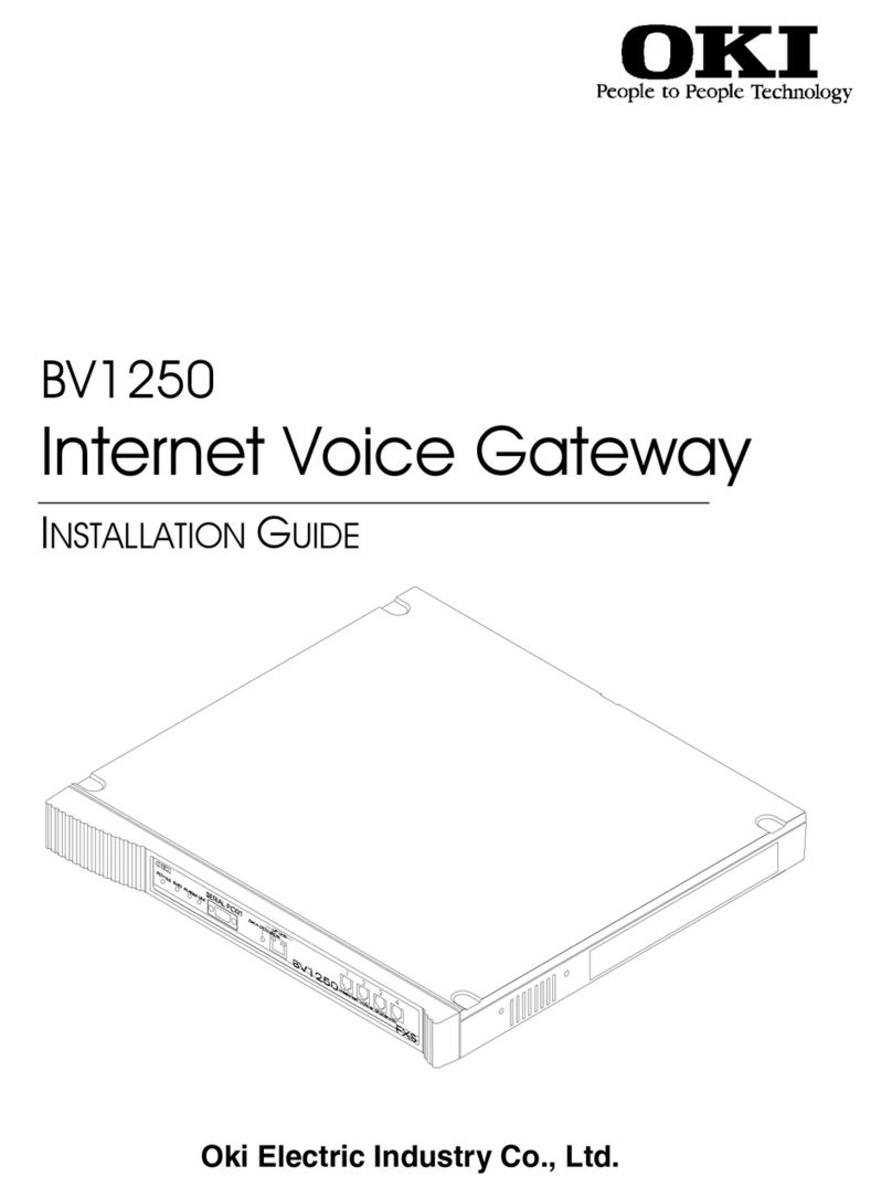
Oki BV1250 Use and care manual

BV1250
Internet Voice Gateway
TECHNICAL REFERENCE
Oki Electric Industry Co., Ltd.


BV1250 Technical Reference
Rev. 1.0 Page i
!
Safety Warning!
This document contains information relating to the safe
installation, maintenance, and use of the Oki BV1250. Carefully
note all safety precautions and procedures contained in this
document before installing and using the product.

BV1250 Technical Reference
Page ii Rev. 1.0
The BV1250 Internet Voice Gateway and the Maintenance Console
Software are products of Oki Electric Industry Co. Ltd.
Right to reproduce this manual and/or the Maintenance Console
Software is restricted by the Copyright Act.
No part of this document may be reproduced, stored on a retrieval
system, or transmitted in any form or by any means, electronic,
mechanical, photocopying, recording, or otherwise, without the
written permission of Oki Electric Industry Co. Ltd.
Information in this document is subject to change without notice.
The contents of this document and the Maintenance Console
Software have been prepared with the utmost care. However, if you
notice an ambiguous point or omission, please contact an authorized
agent.
No responsibility will be taken by our company with respect to
consequences resulting from the use of the Maintenance Console
Software and/or the content and interpretation of the information
contained in this manual.
2000, Oki Electric Industry Co. Ltd.
Ethernet is a registered trademark of Xerox Corporation.
MS-DOS and Windows are registered trademarks of Microsoft
Corporation.
Other companies and product names mentioned in this manual are
the registered trademarks or services marks of their respective
companies.
Revision 1.0
Printed in the USA

BV1250 Technical Reference
Rev. 1.0 Page iii
Limited Warranty
Oki Electric Industry Co., Ltd. warrants that these products (BV1250 and
Maintenance Console Software) are free of manufacturing defects during the
warranty period and while operating under normal conditions. In the event of
failure, a replacement unit and/or software will be provided free of charge.
This warranty covers this product only and is subject to the following conditions:
1. Oki Electric warrants the media upon which the Maintenance Console
Software is recorded to be free from defects in materials and workmanship
under normal use for a period of ninety (90) days from the date of purchase.
In the event any media prove to be defective during the warranty period,
user’s remedy shall be to return media to Oki Electric for replacement.
2. Oki Electric does not accept liability for loss or damage caused by the user's
mishandling, misoperation, or damages occurring as a consequence of
unusual events such as fire, earthquake, or flood.
3. Regarding the quality and functionality of the Maintenance Console Software
and this Installation Guide, Oki Electric holds no liability for the conformity of
the equipment to the purpose of use by the user and the marketability. Oki
Electric does not accept liability for any loss or damage occurring directly or
indirectly thereof.
4. No responsibility will be taken regarding the results obtained by the use of the
BV1250 and/or the Maintenance Console Software and/or this Installation
Guide.
5. Media such as this Installation Guide, floppy disks, CDs, etc., are supplied
with the Maintenance Console Software as a package and shall be used for
the Maintenance Console Software only. It is strictly forbidden to make a
copy of the Maintenance Console Software other than a back-up copy. Oki
Electric holds no liability for consequences incurred by the use of the copied
media.
Others
1. It is strictly forbidden to offer the MCS program to a third party as such or
after adding modifications. If this program is used by a third party, that use
infringes upon the copyright of the author and it becomes the author's right to
demand compensation.
2. Customer services are available at our company's head office and at our
service locations.

BV1250 Technical Reference
Page iv Rev. 1.0

BV1250 Technical Reference
Rev. 1.0 Page v
Table of Contents
BV1250 Description
BV1250 DescriptionBV1250 Description
BV1250 Description ................................
................................................................
................................................................
................................................................
............................................
........................
............1
11
1
1. Specifications...................................................................................................................................... 3
2. BV1250 External Views ...................................................................................................................... 5
2.1 Base Unit Configuration ............................................................................................................. 5
2.2 BV1250 External Features.......................................................................................................... 6
3. BV1250 Parts...................................................................................................................................... 8
BV1250 Maintenance and Troubleshooting
BV1250 Maintenance and TroubleshootingBV1250 Maintenance and Troubleshooting
BV1250 Maintenance and Troubleshooting ................................
................................................................
.......................................
..............
.......1
11
1
1. Routine Maintenance .......................................................................................................................... 3
1.1 External Cleaning ....................................................................................................................... 3
1.2 Periodic inspection...................................................................................................................... 4
1.3 File Management ........................................................................................................................ 5
2. Trouble Diagnosis and Corrective Action .......................................................................................... 7
2.1 Fault Processing.......................................................................................................................... 8
2.2 Guide to Trouble Indications ...................................................................................................... 9
2.3 Fault Log Codes and Corrective Action.................................................................................... 10
3. Trap Information Sent to NMS.......................................................................................................... 14
4. FAX Issues ........................................................................................................................................ 17
5. Fuse Replacement............................................................................................................................. 18
6. Replacing the BV1250 Fan ............................................................................................................... 19
7. Common Problems and Solutions..................................................................................................... 21

BV1250 Technical Reference
Page vi Rev. 1.0
On-line Command Reference
On-line Command ReferenceOn-line Command Reference
On-line Command Reference ................................
................................................................
..........................................................
....................................................
.......................... 1
11
1
1. Command Reference Overview ...........................................................................................................3
1.1 Command Descriptions ...............................................................................................................4
1.2 ACT and SBY .............................................................................................................................4
1.3 Command Examples....................................................................................................................5
1.4 Parameter Notation......................................................................................................................5
1.5 Response Messages .....................................................................................................................5
1.6 Continuous Mode and Page Mode Display .................................................................................6
2. Utility Commands................................................................................................................................7
3. Common Error Numbers for Maintenance Commands.......................................................................9
4. Command Summaries........................................................................................................................11
5. Command Descriptions .....................................................................................................................19
5.1 Equipment Commands ..............................................................................................................21
5.2 Maintenance Console Commands .............................................................................................54
5.3 Numbering Plan Commands......................................................................................................62
5.4 Line Information Commands.....................................................................................................90
5.5 Management Commands ......................................................................................................... 112
5.6 Report Commands...................................................................................................................116
5.7 Maintenance Commands .........................................................................................................127
5.8 LAN Interface Commands ......................................................................................................137
5.9 FXO Interface Commands.......................................................................................................149

BV1250 Technical Reference Description
Rev. 1.0 Page 1
BV1250 Description
The Oki BV1250 Internet Voice Gateway (IVG) is a self-contained device that
allows organizations to route both voice and fax communications over any IP
compatible network. Oki’s IVG seamlessly bridges existing PBX, key telephone,
analog, and PSTN telephone systems with digital data networks. This technology
allows organizations to more fully utilize existing intranet and Internet facilities.
Most importantly, since communications take place over digital data networks, the
high cost of long distance communications over conventional public telephone
networks is eliminated.
Salient features of the BV1250 include:
•Analog terminal, PBX, PSTN, and G3 Fax communications achieved
over IP network.
•High-quality voice compression encoding that can be configured on a
priority basis to automatically select between 64kbps PCM stream as
either G.729A (8kbps), G.723.1 (5.3kbps) or G.723.1 (6.3kbps)
compression, packet priority control, and bandwidth management.
•Oki’s proprietary dynamic jitter buffer and Dynamic Echo
Cancellation assure uninterrupted and natural speech communications.
•All four BV1250 unit ports are capable of real-time fax transmission
using IP transmission, taking full advantage of the data network’s
flow and data control (TCP transmission).
•Compliant with H.323 Version 2 network protocols and interoperable
with all H.323 compliant devices.
•In non-H.323 networks, provides unified telephone numbering
management using both internal (within the unit) and external DNS
(Domain Name System) functions.
•Network management control through SNMP (Simple Network
Management Protocol – MIBI and MIBII).
•Easy remote maintenance using Oki’s Maintenance Console Software
(Windows 95 & 98 operating system).

Description BV1250 Technical Reference
Page 2 Rev. 1.0

BV1250 Technical Reference Description
Rev. 1.0 Page 3
1. Specifications
BV1250 Internet Voice Gateway (US = United States ver., JPN = Japan ver., EU = European ver.)
GENERAL: Operational unit consists of a base unit, an E&M/E&M-OD, FXS, FXO, or BRI line interface board.
Physical: Dimensions W = 420mm (17”), D = 400mm (14”), H= 53mm (3”)
Weight -4.5Kg or less(10lbs or less)
Color Silver gray (Munsell value: 3.5Y8/0.5)
Power: Input 90VAC-264VAC
Consumption 40VA or less
Environment: Temperature range 0o C to 40o C
Compliance: Safety US - UL1950/cUL950 JPN – JEIDA EU – CE Mark
EMC US – FCC part15 ClassA/ICES-003 ClassA
JPN – VCCI ClassA EU – CE Mark
Redundancy: Single
Voice
Compression:
Protocol G.729A CS-ACELP (8.0kbps)
G.723.1 CS-ACELP (5.3kbps)
G.723.1 MP-MLQ (6.3kbps)
Compression Rate 8 Kbps, 5.3kbps, 6.3kbps
Jitter Absorption 2 sec. max.
MAINTENANCE INTERFACES: Includes both serial and LAN interface
Serial: Connector RS-232C (D-sub 9-pin) (7 bit shift control OFF)
Port Configuration 9600bps , 8, 1, None XON/XOFF
LAN: (Uplink) Connector
Data Transfer
RJ45
10Mbps
(Router: Cross-connect cable
Hub: Straight-connect cable)
Compliance 10BaseT (IEEE802.3)

Description BV1250 Technical Reference
Page 4 Rev. 1.0
LINE AND FAX INTERFACES: A functional BV1250 unit must have a Line Interface card installed. The interface may be FXS
(analog), FXO (analog), E&M (Types 1 and 2), or E&M–OD (Type 5). The G3 facsimile interface is
available with all of the above.
E&M (option): Component PCB board
Terminal PBX E&M
Lines 4 maximum
Channels 4 simultaneous
Resistance 600 ohms
Start-up method US = Type 1 or Type 2 JPN = Type 5 EU = Type 1, Type 2, Type 5 (OD)
Connection Confirmation Immediate, Delay-dial, or Wink-start
Selection signal DP 10/20 PPS or DTMF
Connector Simple solderless / RJ45
Compliance ITU-T Rec. Q.517
Model Name :EMIF FIC :TL11E, TL12E, TL31E, TL32E
Registrant :OKI INDUSTRY CO LTD , Reg. No.:1XLUSA-33761-CN-E, Grant Date :04/27/1999
Canadian Approval CS03, Model Name :EMIF E&M Certification No. :187 9837 A
FXS (option): Component PCB board
Terminal Analog Telephone or Key Telephone System
Lines 4 maximum
Channels 4 simultaneous
Resistance 400 ohms (Including terminal resistance)
Start-up method Loop start
Selection signal DP 10/20 PPS or DTMF
Connector Simple solderless / RJ11
Ringer freq. 20Hz/25Hz/50Hz
Compliance ITU-T Rec. Q.517
FXO(option): Component PCB board
Terminal Analog CO Lines, Key Telephone System, PBX
Lines 4 maximum
Channels 4 simultaneous
Resistance 288 ohms (Including terminal resistance)
Start-up method Loop start
Selection signal DP 10/20 PPS or DTMF
Connector Simple solderless / RJ 11
Compliance ITU-T Rec. Q.517
Model Name :FXO FIC :O2LS2
Registrant :OKI INDUSTRY CO LTD, Reg. No:1XLJPN-33760-CN-E Grant Date :04/27/1999
Canadian Approval CS03, Model Name: FXO, Certification No:187 9903 X
Fax Lines 4 max
Data transfer 9600 bps/4800bps
Transmission Control G3

BV1250 Technical Reference Description
Rev. 1.0 Page 5
2. BV1250 External Views
The external characteristics of a BV1250 unit are shown below.
2.1 Base Unit Configuration
Figure 2-1 illustrates the basic configuration of all versions BV1250 units.
The only difference between unit configurations is that the line interface
connector ports appearing on the front panel vary between FXS, FXO,
E&M, and E&M-OD equipped units. These differences are noted in Figure
2-2.
Figure 2-1: BV1250 External View (FXS shown)
2.2
NOTE:
Appearance of Line
Interface varies
based on type of
interface installed.
(See description in
following section,
External Features.)
Front
Width = 420mm (17")
Depth = 400mm (14")
Height =
53mm (3")
Rear

Description BV1250 Technical Reference
Page 6 Rev. 1.0
BV1250 External Features
The BV1250 base unit front and rear panels have various physical elements
associated with supplying power to the unit and providing operational status
information. Figure 2-2 illustrates these features. These features are
described in greater detail in Table 2-1 on the following page.
Figure 2-2: BV1250 External Features

BV1250 Technical Reference Description
Rev. 1.0 Page 7
Table 2-1: Description of BV1250 External Feature
Item Description
1 Power lamp Indicates power ON when lamp lit Green lamp
2 Busy lamp When port is in use, lit lamp indicates line is busy Orange lamp
3 Alarm lamp Indicates alarmed condition detected in unit when lamp lit or blinking Red lamp
4 On-line lamp Indicates unit’s operational condition
When lit, unit operating normally
When not lit, unit is starting-up or is off-line
When blinking, unit is shutting-down
When blinking slowly, urgent maintenance required
Green lamp
5 Serial port Connector for serial cable connection of maintenance console terminal DB9-F
6 Link lamp Indicates LAN link is operating normally when lit Green lamp
7 Uplink connector 10BaseT connector for LAN RJ45
9 Collision lamp Indicates frame collisions are occurring when lit. Yellow lamp
8 Data lamp Indicates that data is being sent/received when lamp is lit or blinking Green lamp
10
.
Line interface
a. FXS
b. FXO
c. E&M
d. E&M-OD
Line interface board connectors
Four TEL connectors of FXS board equipped units
Four FXO connectors of FXO board equipped units
Eight E&M connectors for E&M board equipped units
Four E&M-OD connectors for E&M-OD board equipped units
Connectors
supplied with
board
11 Fan assembly Serviceable fan assembly for cooling of unit
12 FG terminal Terminal strip for frame ground
13 Power connector Connector for AC power cord
14 Fuse holder Housing for fuse
15 Power switch Turns power to the base unit ON and OFF Toggle switch

Description BV1250 Technical Reference
Page 8 Rev. 1.0
3. BV1250 Parts
Below is a listing of BV1250 parts along with the part and product numbers.
Product Name Oki Networks Part Number Oki-J Product No.
Basic Parts
BV1250 Base Unit 100101 4YA1158-1121G002
BV1250 Accessories
BV1250 Accessories, Europe
100102
100114
4YA1158-1123G002
4YA1158-1123G003
BV1250 FXS Interface kit
BV1250 FXO Interface kit
BV1250 E&M Interface kit
BV1250 AP interface retrofit kit
BV1250 FXO interface retrofit kit
BV1250 EM interface retrofit kit
BV1250 OD Interface retrofit kit (Japan)
BV1250 FXO Interface kit, Japan
100103
100104
100105
100107
100108
100109
100113
100112
4YA1158-1124G001
4YA1158-1125G002
4YA1158-1146G001
4YA1158-1144G001
4YA1158-1142G001
4YA1158-1143G001
4YA1158-1145G001
4YA1158-1125G001
BV1250 Rack Mount Kit 100106 4YA1158-1122G001
Maintenance Console Software 103012
BV1250 Installation Guide
BV1250 Technical reference
103111
103112
Ancillary Parts and Spares
BV1250 General Description 103115
BV1250 User's Guide 101004 3PP1158-5120P101
BV1250 Indicator Label for FXS unit 101101 3PP1158-5220P001
BV1250 Indicator Label for FXO unit 101102 3PP1158-5220P002
BV1250 Indicator Label for E&M unit 101103 3PP1158-5220P004
DDK Connectors for AP unit Installation 101006 224A3223P0020
DDK Connectors for E&M unit Installation 101008 224A3231P0040
DDK Connectors for OD unit Installation 101010 224A3231P0060
Screws for Base unit Type M4 101011 P(SW+W)4-10-FRC
Screws for Interface card Type M3 101012 P(SW+W)3-8-FRC
BV1250 Cooling Fan unit 101105
BV1250 Fuse, Rating 250V, 3.15A 101106
PC Serial cable for Maintenance Console 101013 --

BV1250 Technical Reference Maintenance and Troubleshooting
Rev. 1.0 Page 1
BV1250 Maintenance
and Troubleshooting
The BV1250 unit is a low maintenance electronic device that, once installed and properly
configured, should need only infrequent attention.
Other than an occasional external cleaning, all maintenance activities should be performed
by qualified personnel. General maintenance activities include routine checks of data logs
maintained in the unit’s log files, system file updates, and should it becomes necessary, the
replacement of the unit’s fuse and fan assembly.
In the event that a unit’s performance fails or becomes unstable, it may be necessary to
troubleshoot the unit to diagnose and correct the problem.
In this section, the following topics are discussed:
•Routine Maintenance
•Troubleshooting and Corrective Action
•Fault Messages and Reports
•Error Traps
•Fuse Replacement
•Fan Unit Replacement

Maintenance and Troubleshooting BV1250 Technical Reference
Page 2 Rev. 1.0

BV1250 Technical Reference Maintenance and Troubleshooting
Rev. 1.0 Page 3
1. Routine Maintenance
Routine maintenance involves tasks to be performed on a regular basis even when the
unit gives no evidence of problems or malfunction. These activities are generally
preventative in nature.
1.1 External Cleaning
Depending on the environment in which it is installed, a BV1250 unit may
need occasional cleaning. Cleaning will help to remove accumulated dust and
dirt which can interfere with the proper cooling of the unit and can affect the
operation of the unit’s external switches and buttons.
External cleaning is performed using a cloth dampened with a mild soapy
solution. Simply wipe down the unit to remove dirt and dust taking care that no
excess moisture penetrates the unit.
!
Do not allow moisture to penetrate the unit. Moisture in the
unit can cause serious damage and may produce an electrical
hazard.
When cleaning the external base unit, it is also useful to check the unit fan for
dust build-up. If an excessive amount of dust is present, the fan unit should be
cleaned. See Section 6 for a description of the fan assembly.

Maintenance and Troubleshooting BV1250 Technical Reference
Page 4 Rev. 1.0
1.2 Periodic inspection
Periodic inspection activities should be organized using a maintenance
schedule that specifies regular inspection intervals. Inspection need not occur
frequently but is best when conducted on a routine basis.
With the exception of external inspection, all inspection activities can be
conducted remotely using the Maintenance Console Software or with On-line
commands on a terminal.
Recommended inspection and maintenance activities are shown in Table 1-1
below.
Table 1-1: Periodic Inspection Procedure
Step Action Nominal Condition If trouble. . .
1. Check general
operation.
Check the Alarm lamp on the front
panel of the unit.
Use the MCS to view the equipment
status.
Red ALARM lamp not lit.
All lamps are operating,
(e.g. PWR, CONT, PP.
FAX, and FAN)
Use the MCS Fault Log display or enter the on-line
ELOG command to retrieve the unit’s fault log,
record listed trouble code(s), and refer to the Fault
Messages table for corrective action.
2. Check Trouble
Log.
Use the MCS Fault Log display or
enter the on-line ELOG command to
retrieve the unit’s fault log.
No fault conditions are
displayed in the log.
Record listed trouble code(s) and refer to the Fault
Messages table for corrective action.
3. Restart unit. Power cycle the unit being careful to
use the Shutdown procedure
described in the BV1250 Installation
Guide.
OR
Reboot the equipment using the
MCS Reboot item or the on-line
REBOOT command.
After restart repeat Step 1 this table.
Red ALARM lamp not lit.
All lamps are operating,
(e.g. PWR, CONT, PP.
FAX, and FAN)
Use the MCS Fault Log display or enter the on-line
ELOG command to retrieve the unit’s fault log,
record listed trouble code(s), and refer to the Fault
Messages table for corrective action.
4. Check voice
communication.
Place test calls to and from
extensions associated with the unit.
The ring-back tone (RBT)
can be heard.
Speech quality is normal
and there is little or no
ambient background
noise.
Verify that the access code and destination number
dialed are correct.
Use the MCS or other facility to send a Ping test to
the remote IVG to verify communication.
Use the MCS Fault Log display or enter the on-line
ELOG command to retrieve the unit’s fault log,
record listed trouble code(s), and refer to the Fault
Messages table for corrective action.
5. Check fax
communication
Send test faxes to and from
extensions associated with the unit.
Fax transmitted
successfully.
Verify that the access code and destination
numbers dialed are correct.
Use the MCS or other facility to send a Ping test to
the remote IVG to verify communication.
Use the MCS Fault Log display or enter the on-line
ELOG command to retrieve the unit’s fault log,
record listed trouble code(s), and refer to the Fault
Messages table for corrective action.
NOTE:
The ELOG must be cleared following the correction of a
problem listed in the log. If this is not done, a previously
resolved item will be erroneously displayed in subsequent
reports. After resolving a problem always clear the trouble
log using the MCS or the on-line ELOG-CLR command.
Other manuals for BV1250
1
Table of contents
Other Oki Gateway manuals