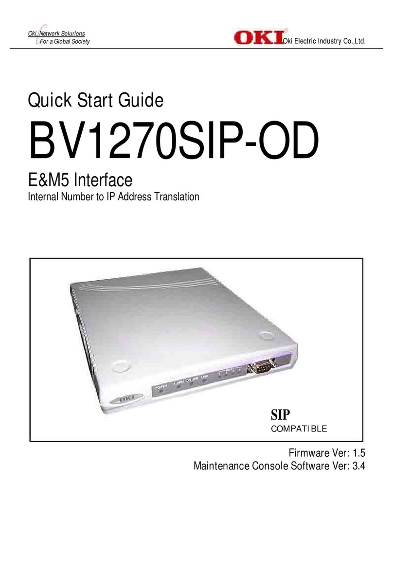
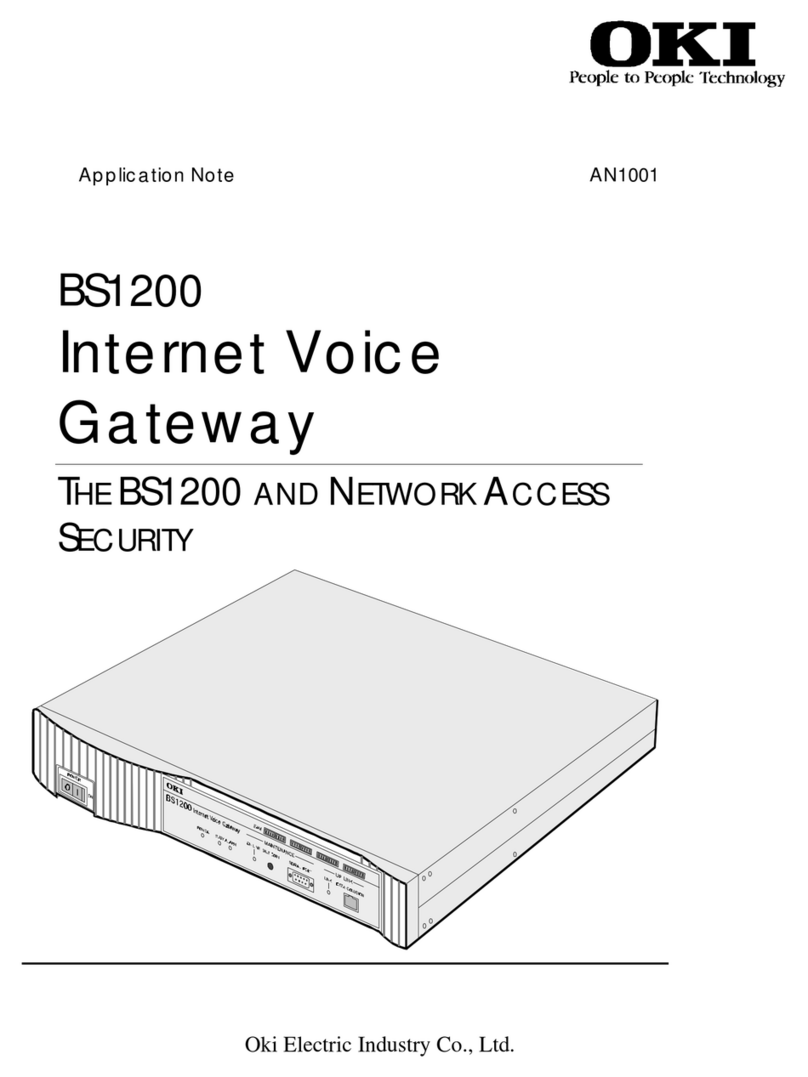
Oki BV1250 User manual

BV1250
Internet Voice Gateway
INSTALLATION GUIDE
Oki Electric Industry Co., Ltd.


Oki BV1250 Installation Guide
Revision 1.0 Page i
!
Safety Warning!
This document contains information relating to the safe
installation, maintenance, and use of the Oki BV1250. Carefully
note all safety precautions and procedures contained in this
document before installing and using the product.

Oki BV1250 Installation Guide
Page ii Revision 1.0
The BV1250 Internet Voice Gateway and the Maintenance Console
Software are products of Oki Electric Industry Co. Ltd.
Right to reproduce this manual and/or the Maintenance Console
Software is restricted by the Copyright Act.
No part of this document may be reproduced, stored on a retrieval
system, or transmitted in any form or by any means, electronic,
mechanical, photocopying, recording, or otherwise, without the
written permission of Oki Electric Industry Co. Ltd.
Information in this document is subject to change without notice.
The contents of this document and the Maintenance Console
Software have been prepared with the utmost care. However, if you
notice an ambiguous point or omission, please contact an authorized
agent.
No responsibility will be taken by our company with respect to
consequences resulting from the use of the Maintenance Console
Software and/or the content and interpretation of the information
contained in this manual.
1999, Oki Electric Industry Co. Ltd.
Ethernet is a registered trademark of Xerox Corporation.
MS-DOS and Windows are registered trademarks of Microsoft
Corporation.
Other companies and product names mentioned in this manual are
the registered trademarks or services marks of their respective
companies.
Revision 1.0a
Printed in the USA

Oki BV1250 Installation Guide
Revision 1.0 Page iii
Safety Precautions
•Never overload electrical outlets. Doing so can cause overheating or fire.
•Never insert or drop any metallic object into openings in the equipment base
unit. Doing so will create a fire hazard or produce electrical shock.
•Never handle the electrical plug with wet hands. Doing so can produce severe
electrical shock.
•Never heat, pull, or place heavy objects on the power cord. Doing so can
damage the power cord and can cause fire or electric shock.
•Never use a voltage other than that specified for this equipment. This
equipment is designed to operate on AC90V to 252V. Doing so can cause
electric shock, equipment failure, and fire.
•Never touch the power plug terminals while the plug is connected to a power
plug outlet. Be certain that the plug is fully inserted into the plug outlet. Any
contact with the plug terminals while they are connected to the outlet can
cause fire, electric shock and other problems.
•Never install this equipment in an area in which it will be exposed to lamp soot,
high humidity, or moisture. Doing so can cause premature equipment failure,
fire, electric shock and other problems.
•Never install the equipment in areas with a great amount of dust, moist
environments, or areas in which other chemical reactions may create corrosive
gases which may act upon the equipment. Doing so can result in premature
equipment failure, fire, and other problems.
•Never install the equipment in an area in which it will be exposed to excessive
vibration. Doing so may result in premature equipment failure, fire, and other
problems.
•Never install this equipment in areas in which it will be exposed to strong
magnetic fields. Doing so may result in poor equipment performance and
possible failure.
•Never install this equipment in a location in which it will be subject to falling.
Doing so can result in personal injury and equipment breakage, failure, fire,
and other hazards.
•Never install this equipment in a location in which it is exposed to prolonged
direct sunlight or excessively high humidity. Doing so can cause equipment
overheating, premature failure, fire, and other problems.
•Never install this equipment in an orientation other than that prescribed in this
document. This equipment has been designed for horizontal installation.
Improper orientation can cause equipment overheating, premature failure, fire,
and other problems.
•Never move this equipment without first turning the power off and
disconnecting all cable connections. Doing so can result in personal injury and
damage to the equipment.
•Never place heavy objects on the base unit in a manner other than that
specified in this manual. Doing so can result in personal injury or damage to
the equipment.
•Never operate this equipment without a proper earth/ground connection as
described in this document. Doing so can result in electrical shock and fire.

Oki BV1250 Installation Guide
Page iv Revision 1.0
Limited Warranty
Oki Electric Industry Co., Ltd. warrants that these products (BV1250 and
Maintenance Console Software) are free of manufacturing defects during the
warranty period and while operating under normal conditions. In the event of
failure, a replacement unit and/or software will be provided free of charge.
This warranty covers this product only and is subject to the following conditions:
1. Oki Electric warrants the media upon which the Maintenance Console
Software is recorded to be free from defects in materials and workmanship
under normal use for a period of ninety (90) days from the date of purchase.
In the event any media prove to be defective during the warranty period,
user’s remedy shall be to return media to Oki Electric for replacement.
2. Oki Electric does not accept liability for loss or damage caused by the user's
mishandling, misoperation, or damages occurring as a consequence of
unusual events such as fire, earthquake, or flood.
3. Regarding the quality and functionality of the Maintenance Console Software
and this Installation Guide, Oki Electric holds no liability for the conformity of
the equipment to the purpose of use by the user and the marketability. Oki
Electric does not accept liability for any loss or damage occurring directly or
indirectly thereof.
4. No responsibility will be taken regarding the results obtained by the use of the
BV1250 and/or the Maintenance Console Software and/or this Installation
Guide.
5. Media such as this Installation Guide, floppy disks, CDs, etc., are supplied
with the Maintenance Console Software as a package and shall be used for
the Maintenance Console Software only. It is strictly forbidden to make a
copy of the Maintenance Console Software other than a back-up copy. Oki
Electric holds no liability for consequences incurred by the use of the copied
media.
Others
1. It is strictly forbidden to offer the MCS program to a third party as such or
after adding modifications. If this program is used by a third party, that use
infringes upon the copyright of the author and it becomes the author's right to
demand compensation.
2. Customer services are available at our company's head office and at our
service locations.

Oki BV1250 Installation Guide
Revision 1.0 Page v
Table of Contents
Chapter 1:
Chapter 1:Chapter 1:
Chapter 1: Introduction
IntroductionIntroduction
Introduction ........................................................................................................................... 1
Chapter 2:
Chapter 2:Chapter 2:
Chapter 2: BV1250 Overview
BV1250 OverviewBV1250 Overview
BV1250 Overview.................................................................................................................. 3
Chapter 3:
Chapter 3:Chapter 3:
Chapter 3: Planning
PlanningPlanning
Planning ................................................................................................................................. 9
3.1 Basic Configuration Overview...................................................................................................... 11
3.2 Worksheets.................................................................................................................................... 30
Chapter 4:
Chapter 4:Chapter 4:
Chapter 4: Physical Installation
Physical InstallationPhysical Installation
Physical Installation........................................................................................................... 133
4.1 Installation Preconditions........................................................................................................... 135
4.2 Unpack and Inventory BV1250 Components .............................................................................. 138
4.3 Board Installation....................................................................................................................... 141
4.4 Mount/Place the Base Unit ......................................................................................................... 149
4.5 Connect Cables........................................................................................................................... 154
4.6 Connect the Computer Terminal Unit with RS-232C Cable ...................................................... 169
4.7 Connect the Network Cable ........................................................................................................ 170
4.8 Power-Up the BV1250 and Verify Operation ............................................................................. 171
4.9 Powering-Down the BV1250 ...................................................................................................... 172
Chapter 5:
Chapter 5:Chapter 5:
Chapter 5: Logical Installation
Logical InstallationLogical Installation
Logical Installation............................................................................................................ 173
5.1 Logical Installation Methods ...................................................................................................... 175
5.2 Maintenance Console Software Overview .................................................................................. 176
5.3 Install Maintenance Console Software ....................................................................................... 177
5.4 Start Maintenance Console Software and Login ........................................................................ 178
5.5 MCS Main Directory Window .................................................................................................... 179
5.6 Create a New Group ................................................................................................................... 182
5.7 Create New Units........................................................................................................................ 184
5.8 Create/Edit Common Configuration........................................................................................... 196
5.9 Configure Units........................................................................................................................... 198
5.10 Transfer Setup and Configuration Files to Units........................................................................ 253
5.11 Synchronize Unit Time and Date ................................................................................................ 258

Oki BV1250 Installation Guide
Page vi Revision 1.0
Appendices
AppendicesAppendices
Appendices ...............................................................................................................................................259
Appendix A: Glossary ......................................................................................................................261
Appendix B: Voice Over IP Addressing.........................................................................................269
Appendix C: Numbering Systems..................................................................................................273
Appendix D: DNS Configuration ....................................................................................................280
Appendix E: Tone Generation.......................................................................................................293
Appendix F: Pad Control and AGC..............................................................................................299
Appendix G: Optimizing Performance.........................................................................................303
Appendix H: Configuration Files....................................................................................................308
Appendix I: FTP File Transfers ............................................................................................................313
Appendix J: Worksheet Masters........................................................................................................318

Oki BV1250 Installation Guide
Revision 1.0 Page vii
List of Figures
Figure 2-1: Simplified IVG network connection .......................................................................................3
Figure 3-1: Basic network configuration .................................................................................................11
Figure 3-2: Examples of undesirable network configurations .................................................................12
Figure 3-3: Sample network configuration with H.323 Gatekeeper ........................................................14
Figure 3-4: DNS options..........................................................................................................................20
Figure 3-5: Relationship of terminals to E&M/E&M-OD.......................................................................21
Figure 3-6: Up to 30 BBV1250-E&M units can be associated with a PBX ............................................22
Figure 3-7: Maximum PBX routing.........................................................................................................22
Figure 3-8: IVG and analog telephones and fax ......................................................................................23
Figure 3-9: IVG and Key Telephone System...........................................................................................23
Figure 3-10: BV1250-AP/FXS connected with PBX ..............................................................................23
Figure 3-11: BV1250-AP/FXS unit terminated with Auto Attendant .....................................................24
Figure 3-12: BV1250-AP/FXS terminated with IVR ..............................................................................24
Figure 3-13: BV1250-FXO unit connection with PBX ...........................................................................25
Figure 3-14: BV1250-FXO unit connection to PSTN .............................................................................26
Figure 3-15: BV1250-FXO unit ports divided to serve both PBX and PSTN.........................................26
Figure 3-16: DTMF Detect......................................................................................................................29
Figure 3-17: AP/FXS Network error detection flowchart........................................................................65
Figure 3-18: Trunk Groups ......................................................................................................................82
Figure 3-19: E&M Network error detection flowchart............................................................................92
Figure 3-20: FXO Network error detection flowchart ...........................................................................126
Figure 4-1: BV1250 chassis cover removal...........................................................................................141
Figure 4-2: Line interface board installation..........................................................................................142
Figure 4-3: E&M line interface board DIP switch locations .................................................................143
Figure 4-4: RJ connector cutouts ...........................................................................................................145
Figure 4-5: Replace unit chassis cover ..................................................................................................146
Figure 4-6: Front label placement..........................................................................................................147
Figure 4-7: Maintenance label placement..............................................................................................148
Figure 4-8: Maintenance Label on BV1250 with E&M Board..............................................................148
Figure 4-9: Base unit footprint and clearance dimensions.....................................................................149
Figure 4-10: Rack mount bracket installation........................................................................................152
Figure 4-11: Securing the unit in the rack..............................................................................................153
Figure 4-12: Rack-mount base unit positioning.....................................................................................153
Figure 4-13: Power Cable Attachment ..................................................................................................155
Figure 4-14: US and EU power cable plugs ..........................................................................................155
Figure 4-15: Earth Ground attachment ..................................................................................................157
Figure 4-16: SG common ground ..........................................................................................................157
Figure 4-17: FXS connector preparation ...............................................................................................158
Figure 4-18: AP connector preparation..................................................................................................159
Figure 4-19: Connecting a rack mounted unit .......................................................................................159
Figure 4-20: Connecting a desktop mounted unit..................................................................................159
Figure 4-21: Connecting a unit to PBX analog Loop Start trunk board ................................................160
Figure 4-22: FXS connector preparation ...............................................................................................161
Figure 4-23: FXO connector preparation...............................................................................................161
Figure 4-24: Connecting a unit directly to PSTN ..................................................................................162
Figure 4-25: Connecting a unit to PBX analog Subscriber Line board .................................................162
Figure 4-26: E&M unit connector orientation and label placement.......................................................163
Figure 4-27: Connecting E&M to PBX E&M Tie Trunk interface .......................................................165
Figure 4-28: E&M-OD connector preparation.......................................................................................166
Figure 4-29: E&M-OD connector wiring ..............................................................................................167
Figure 4-30: Cable restraint installation ................................................................................................168
Figure 4-31: RS-232C pin configuration ...............................................................................................169

Oki BV1250 Installation Guide
Page viii Revision 1.0
Figure 4-32: BV1250 serial port connection .........................................................................................169
Figure 4-33: Uplink connector location ................................................................................................170
Figure 4-34: Router and Ethernet Switch cabling ................................................................................. 170
Figure 4-35: Power switch and front panel indicators........................................................................... 171
List of Tables
Table 3-1: Codec Default Parameters......................................................................................................64
Table 3-2: Codec Default Parameters......................................................................................................91
Table 3-3: Codec Default Parameters....................................................................................................125
Table 4-1: Analog Line Interface Board Kits........................................................................................ 139
Table 4-2: FXO Line Interface Board Kits............................................................................................ 139
Table 4-3: E&M Interface Board Kits...................................................................................................140
Table 4-4: E&M/OD Line Interface Board Kit ..................................................................................... 140
Table 4-5: Speech Line DIP switch settings.......................................................................................... 144
Table 4-6: Type1/Type 2 settings..........................................................................................................144
Table 4-7: E&M connector wiring ........................................................................................................164
Table 4-8: Connector label definitions..................................................................................................165

Chapter 1:
Chapter 1:Chapter 1:
Chapter 1:
Introduction
IntroductionIntroduction
Introduction
This document provides information and procedures needed to install a network of
BV1250 Internet Voice Gateway units. Although the BV1250 installation process is
straightforward, careful planning will smooth the process and allow for trouble-free
expansion and upgrading.
Steps associated with assigning network addresses and creating a network telephone
numbering system should be performed by persons experienced in network
administration. For complex installations, it may be useful to create a diagram of the
network similar to those used in various sections of this document. Planning issues are
addressed in Chapter 3: of this document.
In addition to this introduction, this document is organized into the following chapters:
•BV1250 Overview
•Planning and Preparation
•Physical Installation
•Logical Installation
At the end of this document are appendices that provide detailed information on topics
that will be useful during the planning and installation process.

INTRODUCTION Oki BV1250 Installation Guide
Page 2 of 334 Revision 1

Chapter 2:
Chapter 2:Chapter 2:
Chapter 2:
BV1250 Overview
BV1250 OverviewBV1250 Overview
BV1250 Overview
Oki BV1250 Internet Voice Gateways (IVGs) are self-contained H.323 Version 2
compliant communications devices (Gateways) that allow organizations to route
both voice and fax communications over any TCP/IP network.
Oki BV1250 IVGs can be used to seamlessly bridge PSTN, PBX, Key Telephone,
and analog telephone systems with digital data networks, allowing organizations
to more fully exploit their existing intranet and internet facilities. Most
importantly, since communications take place over digital data networks, the high
cost of long distance communications over conventional telephone networks is
virtually eliminated.
In the simplest sense, a BV1250 IVG unit converts outgoing voice or fax signals
into a digital format, compresses and packages the signal for transmission over
digital TCP/IP networks. On the incoming side, the IVG reverses this process,
receiving voice or fax data packets and translating them back into appropriate
voice and fax signals.
IP Network
Fax
Telephone
Fax
Telephone
Router Router
y
Compress Voice
y
Convert Analog Voice to Digital Voice
y
Packetize Voice and Fax Data
y
Decompress Voice
y
Convert Digital Voice to Analog Voice
y
De-packetize Voice and Fax Data
IVG IVG
Figure 2-1: Simplified IVG network connection
In summary, Oki’s IVGs provide organizations with a reliable one-box solution
for high quality integrated voice and facsimile communications using existing
LAN/WAN environments without interrupting or compromising ongoing data
communications.

OVERVIEW Oki BV1250 Installation Guide
Page 4 of 334 Revision 1.0
The BV1250 IVG incorporates many features that help to assure a robust and
easy-to-use product that delivers high quality voice communication and error free
fax transmission.
Modularized Base Unit
The BV1250 IVG base unit has a compact modular design that allows it to
be configured for easy installation and connection within existing network
environments.
Physical configuration is accomplished by installing the desired board or
boards in the base unit.
Line Interface Options
Oki’s modular design permits identical base units to be quickly and easily
set up with different line interface boards-- AP/FXS, FXO, E&M, and BRI.
These boards provide support for most telephone communications
interfaces and can be interconnected using RJ or DDK type connectors.
FXS: The AP/FXS line interface board is installed in units that will be
connected to simple analog devices such as telephones, fax
machines, and Key Telephone Systems (KTS).1
1The AP and FXS boards are interchangeable. In this document this interface is referred to as AP/FXS
or FXS.

Oki BV1250 Installation Guide OVERVIEW
Revision 1.0 Page 5 of 334
FXO: The FXO line interface board is installed in units that will be
connected directly to a PSTN or to the analog station/line ports of a
PBX.
E&M: Install an E&M line interface board in units that will be connected
directly to a Private Branch Exchange (PBX) E&M interface.2
The standard E&M board supports Types 1 or 2, two or four-wire
interfaces. The E&M-OD board supports a Type 5 interface.
Fax Interface
Each of the four BV1250 unit ports are capable of real-time fax
transmission using IP (T.38) transmission, thereby taking full advantage of
the data network’s flow and data control (TCP transmission).
DTMF Detect and Regeneration
BV1250 units are capable of detecting and regenerating DTMF signals.
Sending units are able to detect and convert DTMF tones for reliable
transmission. On the receiving end, the unit regenerates DTMF tones,
assuring accurate transmission when interfacing with Auto Attendant/Voice
Mail or Interactive Voice Response systems.
Voice Quality
All BV1250 units provide high-quality voice compression encoding which
can be configured on a priority basis to automatically select between
64kbps PCM stream as either G.729A (8kbps), G.723.1 (6.3kbps) or
G.723.1 (6.4kbps) compression, packet priority control, and bandwidth
management.
In addition, Oki’s proprietary dynamic jitter buffer and Dynamic Echo
Cancellation further assure uninterrupted and natural speech
communications.
Capacity
Each BV1250 unit supports up to four ports. Each of the four ports can be
configured for telephone service and any single port can be designated for
G3 fax service.
Network Connectivity
BV1250 units support a 10BaseT Ethernet interface for network
connection. WAN connectivity is provided through any IP router.
2The E&M line interface board comes in two versions. The standard E&M board supports Type 1 and
Type 2 PBX interfaces. The E&M-OD board support a Type 5 PBX interface.

OVERVIEW Oki BV1250 Installation Guide
Page 6 of 334 Revision 1.0
Interoperability
All BV1250 IVGs, irrespective of their configurations, are interoperable
among themselves and with other OKI Internet telephony products. In
addition, all BV1250 units are H.323 Version 2 compliant and when
installed in H.323 Version 2 compliant networks, are interoperable with
other H.323 Version 2 compliant devices.
H.323 Compliance
All Oki BV1250 units are H.323 Version 2 compliant.
When implemented within an H.323 network, units are simultaneously
managed as H.323 compliant gateways, using H.323 Gatekeeper device call
control, address management, and bandwidth control capabilities.
IP and Telephone Numbering Management
Oki BV1250 units employ a unified telephone numbering management
system. It is easy to create a numbering plan that conforms to existing PBX
and PSTN numbering plans.
IP to telephone-number translation can be handled in a number of ways.
1. In H.323 compliant networks (e.g. Gatekeeper devices are employed)
translations are handled by an H.323 Gatekeeper device.
2. In networks not employing an H.323 Gatekeeper, IP to telephone-
number translations can be handled by external DNS (Domain Name
System) servers
3. In the absence of external DNS servers are the internal DNS
capabilities of BV1250 units can be used.

Oki BV1250 Installation Guide OVERVIEW
Revision 1.0 Page 7 of 334
4. Finally, external and internal DNS capabilities can also be combined to
optimize network performance.3
Mounting
BV1250 units can be installed on a desktop or rack-mounted in a standard
19" rack configuration, using the optional rack mounting kit.
SNMP Capabilities
Oki BV1250 units can be configured to use network management control
through SNMP (Simple Network Management Protocol - MIBII).
Remote Control and Management
Installation and configuration of the BV1250 units is performed using Oki’s
Maintenance Console Software (MCS) running on the Windows 95
operating system.
For first-time installation the Maintenance Console Software is used in
conjunction with a common RS232C interface in order to establish a unit’s
new IP addressing. Once this is done and units are on-line in the network,
the Maintenance Console Software can be used to configure and
troubleshoot units remotely.
Alternatively, BV1250 configuration files can be manually configured and
uploaded to units, or BV1250 on-line configuration commands can be
entered directly to a unit. The advanced unit configuration techniques are
applied using an RS-232, LAN, or a Telnet/FTP link.
3Using this configuration can restrict interoperability with other manufacturer’s H.323 devices.

OVERVIEW Oki BV1250 Installation Guide
Page 8 of 334 Revision 1.0

Chapter 3:
Chapter 3:Chapter 3:
Chapter 3:
Planning
PlanningPlanning
Planning
BV1250 IVG units provide versatile and reliable low cost voice and fax over IP
networks. The equipment and software are designed to be easily integrated into
existing data and telephony networks. Proper planning will make the installation
process go more easily and will assure that the network can be easily maintained
and upgraded.
This chapter covers the following planning related topics:
•General discussion of BV1250 IVG network configurations and components.
•Presentation and description of worksheets used to record information needed
to install and configure a BV1250 network.

PLANNING Oki BV1250 Installation Guide
Page 10 of 334 Revision 1.0
Other manuals for BV1250
1
Table of contents
Other Oki Gateway manuals
Popular Gateway manuals by other brands

Tescom
Tescom Ts2 user guide

IOGear
IOGear MediaShair 2 user manual

LANSITEC
LANSITEC 100-13248 manual

SMC Networks
SMC Networks SMCWTVG Specifications

ZyXEL Communications
ZyXEL Communications ZyXEL ZyWALL IDP 10 quick start guide

Elitegroup Computer Systems
Elitegroup Computer Systems GWS-HZW1 Quick installation guide