Unit 1, F arranshane House
1 B allygore Ro ad
Antrim
Co. Antrim
Northern Ireland
BT41 2R Nwww.heatboss .co.uk
+44(0)28 9422 8141
info@heatboss. co.uk
Safety Precautions
The heatboss® stat should not be used in places where
it can be expos ed to water.
08
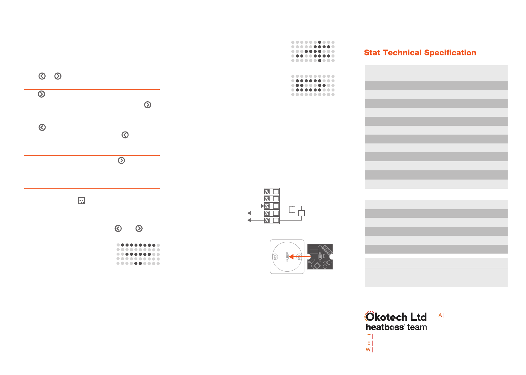
Therm ostat Ty pe
S oftware Cl ass ificat ion
Sa fety Class ificat ion
Battery Lif e
Measurement Interva l
Co ntrol A ccur acy (tem p. / R H)
P ow er S ourc e
Scann ing T em perature Ran ge
Tem peratur e Co ntrol R ange
S ize
We ight
Intelligent Electronic
Wireless Stat
Class A
Class II
Up to 1.5 years
Every minute
+/- 1°C / +/- 5%
2x 1.5V Lithium AA / P ower Module
-9°C to 45°C
-9°C to 45°C
L: 95mm Ø: 8 5mm
113g
IP Cl as s II Co mpletely protected by its enclosure
heatboss® thermostat power module
07
How do I...
06
Increase room temperature
Press for 3 seconds until display starts to flash. T his
brings you into target temperature edit mode. Press
until desired target temperature is obtained.
Decrease room temperature
Press for 3 se conds until target temperature starts to
flash. It will show the current target. Press until desired
target temperature is obtained.
Boost
If no s cheduleor boost is running, press for 3
seconds.Thebo ost target will be set to 20°C or 2°C above
the current room temperature if already above 20°C .
Setup schedules
Log-on t o heatboss®user interface. Navigate to the
desired ro om and click . From here you can create,
modify or delete schedules.
Reset
To reset the thermostat press and hold and
buttons simultaneously for 10 se conds. The display will
flash the target temperature. W hen
device displays th e sy mbol to the right
release both buttons . The thermostat
will now start to sync to hub.
Display room temperature
Press or once.
Power mode
If your thermostat is powered from the
mains by the P ower Module it willdisplay
the s ymbol to the right upon startup. In this
mode the relays in the thermostat Power
Module are controlled.
If your thermostat is po wered by battery it
will display the icon to the right upon startup.
In this mode the relays are not controlled
and the motion sensor is disabled.
This is used to power the heatboss® stat and allows the
stat to control external s ystems such as zone valves. It
contains two relays R1and R2which are c ontrolled for
heating and c ooling respectively. There is a common
header input that willbe s witched by the relays. The
common header is voltage free.
• Ensure module is placed the
correct way up, then fix onto the
back of the bac kplate with the
two screws provided.
• Wire in power 240V A C (L = live, N = neutral)
• If the relays are going to be used to control/signal
ext ernal equipment wire thes e now.The ‘C ’ (voltage free)
common willbe sw itched by R1and R 2.
• Ensure wires are not exerting any force on any of the
components of the P C B.
• Scre w the back plate to the s ocke t.
Live
Neutral
C
SW2
SW1
R2R1
240V~
Type
Sa fety Class ificat ion
P ow er Mod ule T echn ica l S pec ificat ion
S ize
Mechan ica l Co ntac t
Re lay S witch M ax
Re lay Voltage S witche d
Use for heatboss® st at only
Class I I
65mm x 65mm
Re lay
5v
Voltage free via C pin header
Stat Power
ModuleBackplate
How to install thermostat power module
Radio Signal 2.4Ghz mesh Zigbee


