Olimpia electronics GRL-39/ADR User manual

GENERAL
o
These luminaires are used indoors (ta 40 C)
where emergency light is needed. Each
luminaire must be connected permanently to
the mains power supply.
ADDRESS OPERATION
The luminaires can be connected to a
GR-6500 address panel. For address
operations refer to the installation manual of
the panel.For address module connections
see page 4. For dip-switch addressing
selection see page 5 and 6.
OPERATION DESCRIPTION
When the unit is connected to the mains power
supply (after connecting the battery) the
indicator LAMP FAULT – BATT. FAULT remains
OFF whereas the indicator POWER CHARGE
blinks to indicate that the batteries are charging.
When the batteries are fully charged this
indicator will light permanently. If this indicator
does not light then probably the battery has not
been connected. If the batteries are connected
and the indicator does not light then contact a
qualified service technician for assistance. The
charging procedure is monitored by a
microprocessor and is based on a 3 stage cycle
thus ensuring a fast and full charge of the
battery. The charge current is supplied by a high
efficiency switch mode power supply which
ensures perfect charging even during the
fluctuations of the mains power supply.
BATTERY CUTOFF
The unit enters this state during the power
supply failure and when the battery has been
fully discharged. In this state the luminaire draws
the least power from the battery in order to
prevent
deep discharge.
MANUAL TESTING
Is accomplished by briefly (<1 sec.) pressing the
TEST button. This permits the user to test the
good operation of the luminaire’s emergency
circuit. The unit simulates a power failure and
the lamps are lit using the batteries. This manual
test does not affect the automatic test.
DIMMING OPTION
When the luminaire is in emergency mode, with
corresponding pressings of the button, we can
choose the illumination of 100%, 50%, 33% or
turned off, either to increase the autonomy time
or not to consume the battery power
unnecessarily. This option is canceled when the
network is restored.
Thank you for your trust in our products
Olympia Electronics - European manufacturer
Page 1 from 7 923039005_09_007
ABS/PC, PC
OPERATION TEMPERATURE RANGE
RELATIVE HUMIDITY
EXTERNAL DIMENSIONS
CONSTRUCTION MATERIALS
TYPICAL WEIGHT
GUARANTEE
OPERATION VOLTAGE
MAXIMUM POWER CONSUMPTION
BATTERIES (Pb)
CHARGING TIME
INDICATIONS - CONTROLS
BATTERY PROTECTION
MINIMUM AUTONOMOUS DURATION
DEGREES OF COVER PROTECTION
PRODUCED IN ACCORDANCE WITH
EMERGENCY ILLUMINATION
LIGHT SOURCE
<24h
POWER-CHARGE indicator, LAMP FAULT–BATT. FAULT indicator, TEST button
From overcharge and deep discharge
IP42
o
5 to 40 C
Up to 95%
3 years (1 year for the battery)
180 min
EN 60598-1, EN 60598-2-22, ΕΝ 55015, ΕΝ 61547, ΕΝ 61000-3-2, ΕΝ 61000-3-3
302 x 94 x 345 mm
220-240V AC/50-60Hz
12V/7Ah
13.5W/14.1VA
3560gr.
2000lm
White LEDs
GRL-39/ADR
TECHNICAL CHARACTERISTICS (for LED MODULE Specifications see page 4)
ADDRESSABLE SELF TESTING
NON MAINTAINED EMERGENCY LUMINAIRE

LAMP TESTING
The luminaire tests the good condition of the
lamps in emergency mode and warns the user
for probable malfunction. If a lamp is found faulty
then the LAMP FAULT indicator starts to blink. To
verify which lamp is faulty use the TEST button. If
the faulty lamp is replaced then the error is
automatically restored and the indicator is
turned OFF.
AUTOMATIC EMERGENCY CIRCUIT TEST
The unit automatically tests the emergency
circuit every 15 days (if the battery and mains
power are connected) . During this test the lamps
are turned ON for 3 seconds using the batteries.
In some cases this function might not be
acceptable (i.e in cases this function might not
be acceptable (i.e in cinema theaters) so the
installer must take this into account during the
installation.
AUTOMATIC DURATION TEST
This test is conducted every 6 months by
simulating a power failure, if the battery and
mains power supply are connected. The unit
lights the lamps using the charged battery and
counts the time until the stated duration. If the
lamps are ON during the end of the test then the
unit is restored to its normal operation (lamps
OFF and battery charging). If the lamps go OFF
before the end of the test then the unit is restored
to its normal operation but the LAMP FAULT /
BATT. FAULT indicator is lit to show that there is
a problem with the battery and that the battery
must be replaced. Let it be noted that this
duration test is also done during every long
power failure. If the power failure lasts for a long
time and the luminaire has entered the
BATTERY CUTOFF mode and the duration
measured is not correct then the fault indicator
will light when the power is restored.
ERASING ERRORS
Erasing errors is accomplished with a prolonged
pressing of the TEST button (>5 sec) when the
unit is connected to the mains power supply. The
fault indicated with the indicator LAMP FAULT /
BATT. FAULT will be erased. If the cause of the
fault has not been restored (i.e burned lamp)
then the indicator will light again. If the fault was
caused by a low emergency duration and you
erase the error then this will be indicated again
during the next duration test after 6 months. In
this case (for duration errors) it is vital to replace
the battery before erasing the error (the error is
automatically erased if the mains power and the
battery are disconnected).
WARNING !!!
1. Every test, installation or maintenance
procedure must be done only by qualified
personnel.
2. The unit must be connected to the mains
power supply using a line fuse rated
accordingly.
3. The replacement of the battery and the
light source must be done using parts of
the same type, by the manufacturer or by
a competent person.
4. If the luminaire must be isolated from the
mains power supply for more than 2
months then the batteries must be
disconnected by removing the battery
connectors.
5. I s not allowed to discard batteries in to t i
common trash bins, they must be
discarded only in battery recycling
points. Do not incinerate.
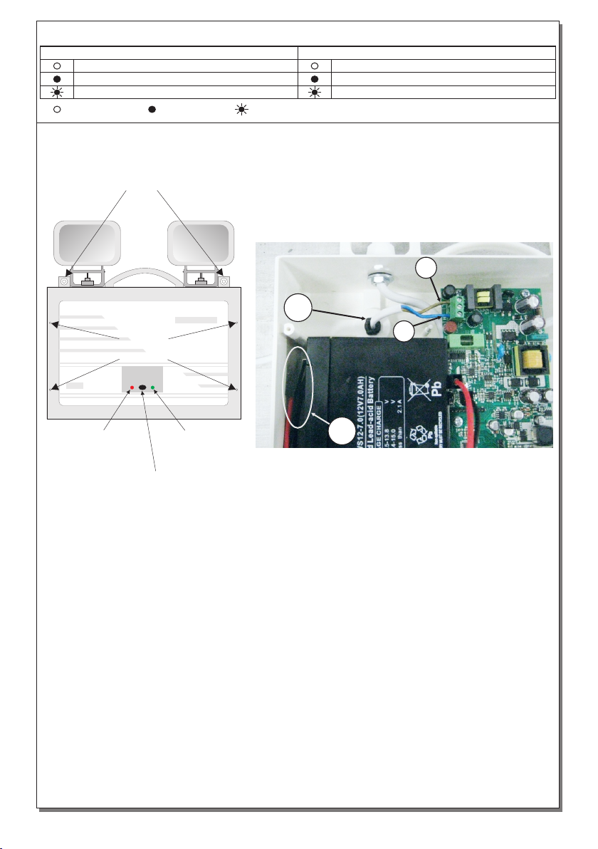
Battery replacement
It can be done only by a competent person
and after the mains interruption.
1. Follow the step 2 of the installation
procedure.
2. Disconnect the cables and remove the
old battery.
3. Connect the new battery with the same
type (step 3 of the installation procedure)
and place it in the position of the old one.
4. Follow the step 5 of the installation
procedure and power the device.
Page 2 from 7 923039005_09_007

1. Install the included mounting accessories to hook the device from the mounting holes (Fig. 1).
2. Unfasten the 4 mounting screws to remove the front plastic cover (Fig. 1).
3. Make sure that the battery’s cables are connected to the respective poles. Black cable to (-) pole
and red cable to (+) pole.
4. Install the included cable gland or the rubber o-ring. Pass through the mains cable and stabilize it
by fastening the cable gland. Connect the wires to the terminal blocks L for live wire and Ν for
neutral (Fig.2).
5. Refit with care the front plastic cover, by fastening the 4 mounting screws (tightening torque
1N*m).
NOTE!! After finishing the installation you must power the luminaire at least for 24 hours for
battery charging to perform the nominal autonomy.
INSTALLATION PROCEDURE (For wall mounting only)
Page 3 from 7 923039005_09_007
INDICATION LED STATUS (with the mains power supply connected)
TEST
button
Cover
retaining
screws
Fig. 1 Fig. 2
LAMP FAULT
BATT. FAULT
indicator
POWER
CHARGE
indicator
Mounting holes
POWER / CHARGE LAMP FAULT / BATT. FAULT
Disconnected battery / not charging Normal operation mode
Charged battery Low emergency duration (replace battery)
Battery under charge Lamp fault (Check lamps and replace if needed)
Indicator ON Indicator BlinkingIndicator OFF
4
N
L
3

Page 4 from 7 923039005_09_007
The light source contained in this luminaire shall only be replaced by the manufacturer, or his
agent, or a similar qualified person.
NOTE! The light source is non-user replaceable.
(*)Non Maintained operation: The luminaire
lights its illumination source, only in power
supply’s failure.
Maintained operation: The luminaire lights its
illumination source, when it is powered by the
mains power supply or not.
NOTE: LED= Light Emitting Diode
LABELING EXPLANATION:
X: Self contained
0: Non Maintained (*)
A: Including test device
B: Including remote rest mode
C: Including inhibiting mode
F: Automatic test gear complying with IEC
61347-2-7 denoted EL-T
180: 3 hours duration
11 Connect the address cables, in the terminal block with the indicating polarity (Fig.3).
12 Address the luminaire by using the dip-switches with the appropriate combinations as you
can see in pages 5 and 6 (Fig.3).
Address module connections
LED MODULE CHARACTERISTICS
Olympia Electronics S.A.
60 °Cmax. across the board
19-23V DC
4.9W
2002163
GRL-39/ADR
Manufacturer
Model Number
Voltage Range
Connections
Nominal Power
Temperature (tc)
Cable connection between main pcb and led module
GR-6500 Loop
LL
11
LL
Fig. 3
12

Page 5 from 7 923039005_09_007
5
6
7
8
9
10
11
12
13
14
15
16
17
18
19
20
21
22
23
24
25
26
27
28
29
30
31
32
33
34
35
36
37
38
39
40
41
42
43
44
45
46
47
48
49
50
51
52
53
54
55
56
57
58
59
60
61
62
63
64
65
66
67
68
69
70
71
72
73
74
75
76
77
78
79
80
81
82
83
84
85
86
87
88
89
90
91
92
93
94
95
96
97
98
99
100
101
102
103
104
105
106
107
108
109
110
111
112
113
114
115
116
117
118
119
120
1
ON
2345678 1
ON
2345678 1
ON
2345678
1
1
1
1
1
1
1
1
1
1
1
1
1
1
1
1
1
1
1
1
1
1
1
1
1
1
ON
ON
ON
ON
ON
ON
ON
ON
ON
ON
ON
ON
ON
ON
ON
ON
ON
ON
ON
ON
ON
ON
ON
ON
ON
ON
2
2
2
2
2
2
2
2
2
2
2
2
2
2
2
2
2
2
2
2
2
2
2
2
2
2
3
3
3
3
3
3
3
3
3
3
3
3
3
3
3
3
3
3
3
3
3
3
3
3
3
3
4
4
4
4
4
4
4
4
4
4
4
4
4
4
4
4
4
4
4
4
4
4
4
4
4
4
5
5
5
5
5
5
5
5
5
5
5
5
5
5
5
5
5
5
5
5
5
5
5
5
5
5
6
6
6
6
6
6
6
6
6
6
6
6
6
6
6
6
6
6
6
6
6
6
6
6
6
6
7
7
7
7
7
7
7
7
7
7
7
7
7
7
7
7
7
7
7
7
7
7
7
7
7
7
8
8
8
8
8
8
8
8
8
8
8
8
8
8
8
8
8
8
8
8
8
8
8
8
8
8
1
ON
2345678
1
ON
2345678
1
ON
2345678
1
1
1
1
1
1
1
1
1
1
1
1
1
1
1
1
1
1
1
1
1
1
1
1
1
1
1
1
1
ON
ON
ON
ON
ON
ON
ON
ON
ON
ON
ON
ON
ON
ON
ON
ON
ON
ON
ON
ON
ON
ON
ON
ON
ON
ON
ON
ON
ON
2
2
2
2
2
2
2
2
2
2
2
2
2
2
2
2
2
2
2
2
2
2
2
2
2
2
2
2
2
3
3
3
3
3
3
3
3
3
3
3
3
3
3
3
3
3
3
3
3
3
3
3
3
3
3
3
3
3
4
4
4
4
4
4
4
4
4
4
4
4
4
4
4
4
4
4
4
4
4
4
4
4
4
4
4
4
4
5
5
5
5
5
5
5
5
5
5
5
5
5
5
5
5
5
5
5
5
5
5
5
5
5
5
5
5
5
6
6
6
6
6
6
6
6
6
6
6
6
6
6
6
6
6
6
6
6
6
6
6
6
6
6
6
6
6
7
7
7
7
7
7
7
7
7
7
7
7
7
7
7
7
7
7
7
7
7
7
7
7
7
7
7
7
7
8
8
8
8
8
8
8
8
8
8
8
8
8
8
8
8
8
8
8
8
8
8
8
8
8
8
8
8
8
1
1
1
1
1
1
1
1
1
1
1
1
1
1
1
1
1
1
1
1
1
1
1
1
1
1
1
1
1
ON
ON
ON
ON
ON
ON
ON
ON
ON
ON
ON
ON
ON
ON
ON
ON
ON
ON
ON
ON
ON
ON
ON
ON
ON
ON
ON
ON
ON
2
2
2
2
2
2
2
2
2
2
2
2
2
2
2
2
2
2
2
2
2
2
2
2
2
2
2
2
2
3
3
3
3
3
3
3
3
3
3
3
3
3
3
3
3
3
3
3
3
3
3
3
3
3
3
3
3
3
4
4
4
4
4
4
4
4
4
4
4
4
4
4
4
4
4
4
4
4
4
4
4
4
4
4
4
4
4
5
5
5
5
5
5
5
5
5
5
5
5
5
5
5
5
5
5
5
5
5
5
5
5
5
5
5
5
5
6
6
6
6
6
6
6
6
6
6
6
6
6
6
6
6
6
6
6
6
6
6
6
6
6
6
6
6
6
7
7
7
7
7
7
7
7
7
7
7
7
7
7
7
7
7
7
7
7
7
7
7
7
7
7
7
7
7
8
8
8
8
8
8
8
8
8
8
8
8
8
8
8
8
8
8
8
8
8
8
8
8
8
8
8
8
8
1
1
1
1
1
1
1
1
1
1
1
1
1
1
1
1
1
1
1
1
1
1
1
1
1
1
1
1
1
ON
ON
ON
ON
ON
ON
ON
ON
ON
ON
ON
ON
ON
ON
ON
ON
ON
ON
ON
ON
ON
ON
ON
ON
ON
ON
ON
ON
ON
2
2
2
2
2
2
2
2
2
2
2
2
2
2
2
2
2
2
2
2
2
2
2
2
2
2
2
2
2
3
3
3
3
3
3
3
3
3
3
3
3
3
3
3
3
3
3
3
3
3
3
3
3
3
3
3
3
3
4
4
4
4
4
4
4
4
4
4
4
4
4
4
4
4
4
4
4
4
4
4
4
4
4
4
4
4
4
5
5
5
5
5
5
5
5
5
5
5
5
5
5
5
5
5
5
5
5
5
5
5
5
5
5
5
5
5
6
6
6
6
6
6
6
6
6
6
6
6
6
6
6
6
6
6
6
6
6
6
6
6
6
6
6
6
6
7
7
7
7
7
7
7
7
7
7
7
7
7
7
7
7
7
7
7
7
7
7
7
7
7
7
7
7
7
8
8
8
8
8
8
8
8
8
8
8
8
8
8
8
8
8
8
8
8
8
8
8
8
8
8
8
8
8
2
3
4
1
ON
2345678
1151
152
153
154
155
156
157
158
159
160
161
162
163
164
165
166
167
168
169
170
171
172
173
174
175
176
177
178
179
180
1
ON
2345678 1
ON
2345678
1
1
1
1
1
1
1
1
1
1
1
1
1
1
1
1
1
1
1
1
1
1
1
1
1
1
1
1
1
ON
ON
ON
ON
ON
ON
ON
ON
ON
ON
ON
ON
ON
ON
ON
ON
ON
ON
ON
ON
ON
ON
ON
ON
ON
ON
ON
ON
ON
2
2
2
2
2
2
2
2
2
2
2
2
2
2
2
2
2
2
2
2
2
2
2
2
2
2
2
2
2
3
3
3
3
3
3
3
3
3
3
3
3
3
3
3
3
3
3
3
3
3
3
3
3
3
3
3
3
3
4
4
4
4
4
4
4
4
4
4
4
4
4
4
4
4
4
4
4
4
4
4
4
4
4
4
4
4
4
5
5
5
5
5
5
5
5
5
5
5
5
5
5
5
5
5
5
5
5
5
5
5
5
5
5
5
5
5
6
6
6
6
6
6
6
6
6
6
6
6
6
6
6
6
6
6
6
6
6
6
6
6
6
6
6
6
6
7
7
7
7
7
7
7
7
7
7
7
7
7
7
7
7
7
7
7
7
7
7
7
7
7
7
7
7
7
8
8
8
8
8
8
8
8
8
8
8
8
8
8
8
8
8
8
8
8
8
8
8
8
8
8
8
8
8
1
1
1
1
1
1
1
1
1
1
1
1
1
1
1
1
1
1
1
1
1
1
1
1
1
1
1
1
1
ON
ON
ON
ON
ON
ON
ON
ON
ON
ON
ON
ON
ON
ON
ON
ON
ON
ON
ON
ON
ON
ON
ON
ON
ON
ON
ON
ON
ON
2
2
2
2
2
2
2
2
2
2
2
2
2
2
2
2
2
2
2
2
2
2
2
2
2
2
2
2
2
3
3
3
3
3
3
3
3
3
3
3
3
3
3
3
3
3
3
3
3
3
3
3
3
3
3
3
3
3
4
4
4
4
4
4
4
4
4
4
4
4
4
4
4
4
4
4
4
4
4
4
4
4
4
4
4
4
4
5
5
5
5
5
5
5
5
5
5
5
5
5
5
5
5
5
5
5
5
5
5
5
5
5
5
5
5
5
6
6
6
6
6
6
6
6
6
6
6
6
6
6
6
6
6
6
6
6
6
6
6
6
6
6
6
6
6
7
7
7
7
7
7
7
7
7
7
7
7
7
7
7
7
7
7
7
7
7
7
7
7
7
7
7
7
7
8
8
8
8
8
8
8
8
8
8
8
8
8
8
8
8
8
8
8
8
8
8
8
8
8
8
8
8
8
121
125
126
127
128
129
130
131
132
133
134
135
136
137
138
139
140
141
142
143
144
145
146
147
148
149
150
122
123
124
Address Dipswitch
setting Address Dipswitch
setting

181
182
183
184
185
186
187
188
189
190
191
192
193
194
195
196
197
198
199
200
201
202
203
204
205
206
207
208
209
210
211
213
212
214
215
216
217
218
219
220
221
222
223
224
225
226
227
228
229
230
231
232
233
234
235
236
237
238
239
240
1
1
1
1
1
1
1
1
1
1
1
1
1
1
1
1
1
1
1
1
1
1
1
1
1
1
1
1
1
1
ON
ON
ON
ON
ON
ON
ON
ON
ON
ON
ON
ON
ON
ON
ON
ON
ON
ON
ON
ON
ON
ON
ON
ON
ON
ON
ON
ON
ON
ON
2
2
2
2
2
2
2
2
2
2
2
2
2
2
2
2
2
2
2
2
2
2
2
2
2
2
2
2
2
2
3
3
3
3
3
3
3
3
3
3
3
3
3
3
3
3
3
3
3
3
3
3
3
3
3
3
3
3
3
3
4
4
4
4
4
4
4
4
4
4
4
4
4
4
4
4
4
4
4
4
4
4
4
4
4
4
4
4
4
4
5
5
5
5
5
5
5
5
5
5
5
5
5
5
5
5
5
5
5
5
5
5
5
5
5
5
5
5
5
5
6
6
6
6
6
6
6
6
6
6
6
6
6
6
6
6
6
6
6
6
6
6
6
6
6
6
6
6
6
6
7
7
7
7
7
7
7
7
7
7
7
7
7
7
7
7
7
7
7
7
7
7
7
7
7
7
7
7
7
7
8
8
8
8
8
8
8
8
8
8
8
8
8
8
8
8
8
8
8
8
8
8
8
8
8
8
8
8
8
8
1
1
1
1
1
1
1
1
1
1
1
1
1
1
1
1
1
1
1
1
1
1
1
1
1
1
1
1
1
1
ON
ON
ON
ON
ON
ON
ON
ON
ON
ON
ON
ON
ON
ON
ON
ON
ON
ON
ON
ON
ON
ON
ON
ON
ON
ON
ON
ON
ON
ON
2
2
2
2
2
2
2
2
2
2
2
2
2
2
2
2
2
2
2
2
2
2
2
2
2
2
2
2
2
2
3
3
3
3
3
3
3
3
3
3
3
3
3
3
3
3
3
3
3
3
3
3
3
3
3
3
3
3
3
3
4
4
4
4
4
4
4
4
4
4
4
4
4
4
4
4
4
4
4
4
4
4
4
4
4
4
4
4
4
4
5
5
5
5
5
5
5
5
5
5
5
5
5
5
5
5
5
5
5
5
5
5
5
5
5
5
5
5
5
5
6
6
6
6
6
6
6
6
6
6
6
6
6
6
6
6
6
6
6
6
6
6
6
6
6
6
6
6
6
6
7
7
7
7
7
7
7
7
7
7
7
7
7
7
7
7
7
7
7
7
7
7
7
7
7
7
7
7
7
7
8
8
8
8
8
8
8
8
8
8
8
8
8
8
8
8
8
8
8
8
8
8
8
8
8
8
8
8
8
8
241
242
243
244
245
246
247
248
249
250
1
1
1
1
1
1
1
1
1
1
ON
ON
ON
ON
ON
ON
ON
ON
ON
ON
2
2
2
2
2
2
2
2
2
2
3
3
3
3
3
3
3
3
3
3
4
4
4
4
4
4
4
4
4
4
5
5
5
5
5
5
5
5
5
5
6
6
6
6
6
6
6
6
6
6
7
7
7
7
7
7
7
7
7
7
8
8
8
8
8
8
8
8
8
8
Page 6 from 7 923039005_09_007
Address Dipswitch
setting Address Dipswitch
setting

Page 7 from 7 923039005_09_007
WARRANTY
Olympia Electronics guarantees the quality, condition and operation of the goods. The period of
warranty is specified in the official catalogue of Olympia Electronics and also in the technical leaflet,
which accompanies each product. This warranty ceases to exist if the buyer does not follow the
technical instructions included in official documents given by Olympia Electronics or if the buyer
modifies the goods provided or has any repairs or re-setting done by a third party, unless Olympia
Electronics has fully agreed to them in writing. Products that have been damaged can be returned to
the premises of our company for repair or replacement, as long as the warranty period is valid.
Olympia Electronics reserves the right to repair or to replace the returned goods and to or not charge
the buyer depending on the reason of defection. Olympia Electronics reserves the right to charge or
not the buyer the transportation cost.
HEAD OFFICE
72nd km. O.N.R. Thessaloniki-Katerini
P.C. 60300 P.O. Box 06 Εginio Pierias Greece
www.olympia-electronics.gr
Table of contents
Other Olimpia electronics Lantern manuals
Popular Lantern manuals by other brands

Humanscale
Humanscale Diffrient Work Light II instructions

SLV
SLV HORN 2 GU10 operating manual

Almat
Almat STELLAsc operating manual

Anslut
Anslut 019728 operating instructions

MELINERA
MELINERA 276520 User Manual and Safety Instructions

Maretti
Maretti WOLTERINCK COSTA LATERNA 14.1324.04 Mounting instructions