GENERAL
o
These devices are used indoors (ta 40 C)
in places where emergency luminaires are
needed. The luminaires GR-470/WP and
GR-472/WP are suitable for corridors
lighting and the GR-471/WP and GR-
473/WP for open area lighting. Each
device must be permanently connected to
mains power supply. In normal operation
the battery is charging. In case of a mains
power supply failure the device will light
the illumination led automatically in
emergency mode. When the mains power
supply is restored the device turns to
normal operation.
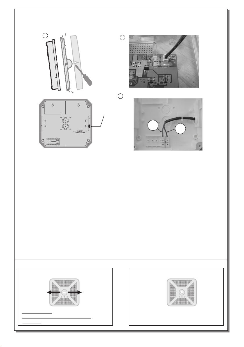
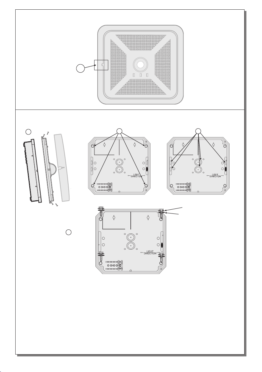
INSTALLATION
To install the luminaire follow the
installation instructions οn page 2.
ΑΤΤΕΝΤΙΟΝ
1. Operations for installation, maintainance
or testing must be done by authorized
personel only.
2. The device must be connected to the
mains power supply thru a fuse dependent
by the total amount of the line’s power
load.
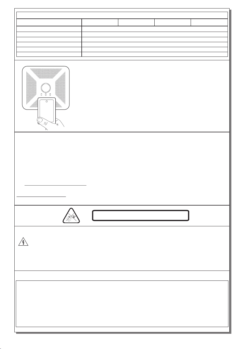
3. It is suggested to check every month the
indication LED for battery charging, and by
!!!
placing the test card (page 5) an
operation test is initiated, to check the
emergency cirquit. The illumination source
should light as long as the card is present
4. It is sugested to check every 6 months
the minimum autononous duration by
disconnecting the mains power supply.
Count the time that the luminaire lights and
in case of less time than the minimum
autonomous duration the battery must be
r e p l a c e d . I f the m e a s u r e d t i m e i s
considerably less than the minimum
autonomous duration
In c as e o f b at t er y o r l ig ht s ou rc e
replacement, these must be replaced by
parts of the same type, by the manufacturer
or by a competent person.
t i
in battery
recycling points. Do not incinerate.
(A-1900)
.
In the opposite condition contact the
installer.
contact the installer.
5. In case of inactive use for a period
greater than 2 months, disconnect the
ba tt ery by pul li ng o ut the ba tt ery ’s
connector.
6. I s not allowed to discard batteries in
to common trash bins, they must
be disca rded only
Page 1 from 6 923473000_09_001
WATERPROOF NON-MAINTAINED LUMINARIES
OPERATION TEMPERATURE RANGE
RELATIVE HUMIDITY
CONSTRUCTION MATERIAL
EXTERNAL DIMENSION
WEIGHT
GUARANTEE
OPERATION VOLTAGE
MAXIMUM POWER CONSUMPTION
BATTERY (Ni-Cd)
CHARGE TIME
INDICATIONS
BATTERY PROTECTION
MINIMUM DURATION
DEGREES OF COVER PROTECTION
PRODUCED IN ACCORDANCE WITH
EMERGENCY ILLUMINATION
LIGHT SOURCE
24 hours
Charge LED, Magnetic Test Contact
Deep discharge and overcharge protection
IP65
3,6V/1 Ah
1 white power LED
2,6W / 2,9VA
5 to 40 C
o
Up to 95%
3 years (1 year for the battery)
EN 60598-1, EN 60598-2-22, ΕΝ 55015, ΕΝ 61547, ΕΝ 61000-3-2, ΕΝ 61000-3-3
3 hour1,5 hour
145lm 80lm
470gr.
220-240V AC / 50-60Hz
TECHNICAL CHARACTERISTICS (for LED MODULE specifications see page 4)
Thank you for your trust in our products.
Olympia Electronics - European manufacturer.
GR-470/WP
GR-471/WP
GR-472/WP
GR-473/WP
158 x 158 x 60,4mm (without decorative bezel)-195 x 195 x 60,4 (with decorative bezel)
ABS/PC, PC