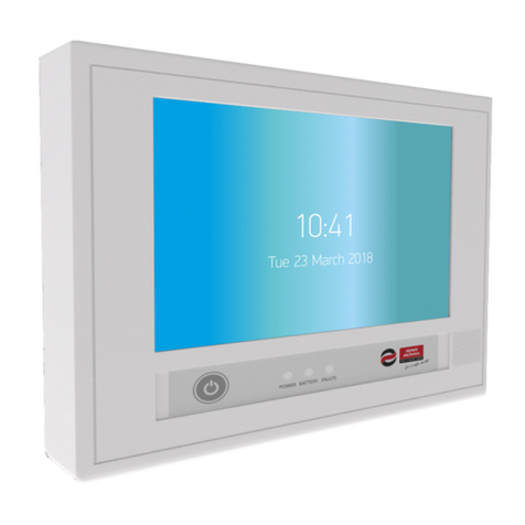
olympia electronics GR-8600 Series Assembly instructions

GR-8600
24VDC Address Central Battery System
Installation
Programming
Use
WARNING!!! PLEASE READ THE MANUAL CAREFULLY BEFORE INSTALLING

Date
26/6/2017
Document
923860006_09_006
Document code
923860006_09_006
Page
2 from 44
Contents
1. General information ................................................................................................................................................................................... 4
1.1 Technical Characteristics ................................................................................................................................................ 5
2. Installation.................................................................................................................................................................................................. 6
2.1 Designing the installation ................................................................................................................................................ 6
2.2 Connecting luminaries on illumination zones .................................................................................................................. 7
2.3 Luminary Types .............................................................................................................................................................. 8
2.4 Connecting the batteries ................................................................................................................................................. 9
2.5 Describing the general inputs and outputs of the panel ................................................................................................ 10
2.6 Powering On ................................................................................................................................................................. 12
3. Indicators - Controls ................................................................................................................................................................................ 13
4. Programming ........................................................................................................................................................................................... 14
4.1 Programming using the keypad .................................................................................................................................... 14
4.1.1 Programming the System...................................................................................................................................... 14
4.1.2 Programming the Zones ....................................................................................................................................... 16
4.1.3 Programming the luminaries ................................................................................................................................. 17
4.1.4 Check Luminary .................................................................................................................................................... 18
4.1.5 Programming Timers ............................................................................................................................................ 18
4.1.6 System Settings .................................................................................................................................................... 19
4.1.7 Clearing Events ..................................................................................................................................................... 21
4.1.8 Change Code ........................................................................................................................................................ 21
4.1.9 Inhibit mode .......................................................................................................................................................... 22
4.1.10 Programming the function test .......................................................................................................................... 22
4.1.11 Programming the capacity test .......................................................................................................................... 22
4.1.12 Capacity test ..................................................................................................................................................... 23
4.1.13 Reset Defaults .................................................................................................................................................. 23
4.1.14 Annual Test ....................................................................................................................................................... 23
4.1.15 Network Setting ................................................................................................................................................. 24
4.2 Programming via PC ..................................................................................................................................................... 25
4.2.1 Programming the zones ........................................................................................................................................ 26
4.2.2 Programming timers .............................................................................................................................................. 26
4.2.3 Programming Points ............................................................................................................................................. 27
4.2.4 Programming the battery capacity and the autonomy ........................................................................................... 27
4.2.5 Dimming Level ...................................................................................................................................................... 28
4.2.6 INHIBIT function .................................................................................................................................................... 28
4.2.7 Adjusting the date and time................................................................................................................................... 28
4.2.8 Battery cooler ........................................................................................................................................................ 29
4.2.9 Change Language ................................................................................................................................................ 29
4.2.10 Staircase time ................................................................................................................................................... 29
4.2.11 Clearing the events log ..................................................................................................................................... 29
4.2.12 Changing the tech code .................................................................................................................................... 30
Date
26/6/2017
Document
923860006_09_006
Document code
923860006_09_006
Page
3 from 44
4.2.13 Network of panels ............................................................................................................................................. 30

4.2.14 Subpanel Setup ................................................................................................................................................ 30
4.2.15 Set Battery Current ........................................................................................................................................... 31
4.2.16 Autodetect Luminaries ...................................................................................................................................... 31
4.2.17 Check Current Zones ........................................................................................................................................ 31
4.2.18 Function test ..................................................................................................................................................... 32
4.2.19 Capacity test ..................................................................................................................................................... 32
4.2.20 Programming the function test .......................................................................................................................... 32
4.2.21 Programming the capacity test .......................................................................................................................... 32
4.2.22 Programming the annual check warning ........................................................................................................... 33
4.2.23 Annual Test ΟΚ ................................................................................................................................................. 33
4.2.24 Setting Defaults ................................................................................................................................................. 33
4.2.25 Changing information ........................................................................................................................................ 33
4.2.26 ΙΡ address ......................................................................................................................................................... 34
4.2.27 Resetting faults ................................................................................................................................................. 34
5 Use ................................................................................................................................................................................................................. 35
5.1 Operation using the keypad .......................................................................................................................................... 35
5.1.1 Current faults ........................................................................................................................................................ 35
5.1.2 Test ....................................................................................................................................................................... 36
5.1.3 Dimming Level ...................................................................................................................................................... 37
5.1.4 Information ............................................................................................................................................................ 37
5.1.5 Reset .................................................................................................................................................................... 39
5.1.6 All Events .............................................................................................................................................................. 39
5.1.7 Earth Test ............................................................................................................................................................. 39
5.1.8 LED test ................................................................................................................................................................ 40
5.2 Operation via PC................................................................................................................................................................. 41
5.2.1 Panel Information .................................................................................................................................................. 41
5.2.2 Zone programming information ............................................................................................................................. 42
5.2.3 Zones status information ....................................................................................................................................... 42
5.2.4 Information Point ................................................................................................................................................... 42
5.2.5 Timer information .................................................................................................................................................. 43
5.2.6 Function test results .............................................................................................................................................. 43
5.2.7 Capacity test results .............................................................................................................................................. 43
5.2.8 Last autonomies .................................................................................................................................................... 43
5.2.9 All events .............................................................................................................................................................. 44
5.2.10 Network information .......................................................................................................................................... 44
5.2.11 Panels network ................................................................................................................................................. 44

Date
26/6/2017
Document
923860006_09_006
Document code
923860006_09_006
Page
4 from 44
Thank you for your trust in our products
Olympia Electronics - European manufacturer
1. General information
The GR-8600 family consists of 3 models of central battery systems for emergency illumination. They are produced
in accordance with the current European norms ΕΝ50171 and ΕΝ50172. Depending on the model, they contain 4
to 8 illumination circuits (zones). Each illumination circuit (zone) can support up to 32 points (addressed luminaries)
that can be programmed individually to operate in maintained or non-maintained mode. Each point provides
information about its lamp and connection status to the panel. A 24VDC voltage is provided by internal power
supply unit to the illumination circuits, when the mains power is active. In case of mains power interruption, the
system is provided with 24VDC from the batteries. The interior of the panel is divided into 2 compartments, the
electronics compartment and the batteries’ compartment. A sensor monitors the batteries’ temperature
continuously.

Date
26/6/2017
Document
923860006_09_006
Document code
923860006_09_006
Page
5 from 44
1.1 Technical Characteristics
GR-8600/300/4
GR-8600/300/8
GR-8600/600/8
Operating voltage
~230V 50-60Hz
Batteries
2 x12V/33Ah
2 x 12V/55Ah
Illumination circuits (zones)
4
8
8
Maximum AC power (input)
900VA
1.4kVA
Max. power output (emergency)
300W
600W
Max. power output (per zone)
75W
Operating temperature range
5 – 40 oC
Degrees of cover protection
ΙΡ 21
Dimensions
67 x 50 x 27 cm
Weight (w/o batteries)
17.3kg
17.6kg
18.7kg
Battery fuse
30A/32V (maxi)
Zones fuse (output)
4A/250V (slow)
Mains fuse
8A/250V (slow)
Battery fan fuse
0.3A/250V (slow)
Type of electric shock protection
Class I
Max. operating altitude (above sea level)
1000m.
Max. relative humidity
95%
Guarantee
2 years
All fuses are size 5x20, battery fuse is 29mm car type.
WARNING: This is a category C2 UPS product. In a residential environment, this product may cause radio
interference, in which case the user may be required to take additional measures.
The class of Volt-meter and Ampere-meter is 1.5.

Date
26/6/2017
Document
923860006_09_006
Document code
923860006_09_006
Page
6 from 44
2. Installation
This section contains information that concerns the designing of the installation, the connection of the panel with
the luminaries and the use of the auxiliary outputs and inputs. The instructions must be read carefully by the
installer that is set to commission the panel. Skill and knowledge about the panel as well as its peripherals is
essential for the good operation of the installation.
All the connections described below must be done with the 230VAC mains power supply isolated and the
battery fuse removed.
2.1 Designing the installation
Before starting to install the cable you must take into account some critical parameters.
- Each luminary installed in any zone can be programmed individually to operate in maintained or non-
maintained mode.
- Each luminary in a zone should get a unique address. If 2 or more luminary are installed with the same
address in a single zone, there will be a data collision and the specific point (address) will not function
properly.
- There is an option for wall mounting the panel with the correct accessories. Please refer to manufacturer
for further information for wall mounting.
2.2 Choosing the correct cable
The cable between the panel and the luminaries must have the following specifications:
2-core twisted pair cable. Normally the cables are unshielded but if the cable passes near
noisy/industrial environment the cables must be shielded.
The cable must have only 2 cores, no other cables. If the environment is too noisy (motors, industrial
etc) a cable with shield must be used.
The cable must have low resistance, below 25 Ohm/km. The total impedance of the cable of each core
from start to finish must be more than 9 Ohm or the maximum voltage drop 3,5V.
The capacitance of the cable must be low (below 200pF/m). The total capacitance of the whole
installation must not exceed 800nF.
The cable that will be used must be resistant to fire for at least 90 minutes.
The cable cross section depends on the consumption of the luminaries on the zone and the total
length. It can be calculated using the table below. The table shows the required cross section of the
cable depending on the length and the consumption.
Typical cable cross section is from 1mm2 to 4mm2 depending on the number of connected luminaires,
topology of the installation and length of cable runs.

Date
26/6/2017
Document
923860006_09_006
Document code
923860006_09_006
Page
7 from 44
The first step to calculate the cross section of the cable is to calculate the current of each zone. You must add the
current of each luminary at 24VDC and multiply with 1.4 factor. Then you pick the correct cross section cable from
the below table. For example, if you want to connect 10 luminaries with lamp 30L the current is 10*85mA = 0.850A
multiply 1.4 factor is 0.850A*1.4 = 1.19A. From the table, for a length less than 100m you must choose cable 1,5
mm2.
0.5 A
1 A
1.5A
2 A
2.5A
3 A
100m
1mm2
1mm2
1.5mm2
2.5mm2
2.5 mm2
4mm2
150m
1mm2
1.5mm2
2.5mm2
2.5mm2
4mm2
4mm2
200m
1mm2
2.5mm2
2.5 mm2
4mm2
4mm2
250m
1mm2
2.5mm2
4mm2
300m
1.5mm2
2.5mm2
4mm2
400m
2.5mm2
4mm2
500m
2.5mm2
4mm2
600m
4mm2
The values on the table are calculated when most of the load (luminaries) are placed at the end of the cable. It is
the worst condition.
It is better to connect the luminaries along the length of the cable.
You can use a star connection at the zone to reduce the voltage drop.
This is recommended to check the currents and the voltage drop when the installation is finish just for verification.
Olympia Electronics recommends the following cables:
1. NHXH FE180/E90.
2. YSLY-OZ
3. LiYCY with shield
2.3 Connecting luminaries on illumination zones
The connection of the luminaries is the same as common luminaries. Below you can see an example:

Date
26/6/2017
Document
923860006_09_006
Document code
923860006_09_006
Page
8 from 44
All connections to the illumination zones as well as any other modifications afterward require that the
mains power supply is isolated and that the battery fuse is removed
Every Zone (illumination circuit) can support up to 32 unique addressed points. Same address between two or
more points in the same zone can lead to malfunction. Point location in a row does not affect proper operation, it’s
not necessary the first point to be address #1. Maximum points table is shown below. Each line refers to zone
number and each column to point number.
Calculate the load according to the model. Do not exceed 75W per zone.
2.4 Luminary Types
The possible luminary types the system can recognize are the following:
1
NO LUMINARY
17
SPOT LIGHT 60L
2
LUMINARY 15 LED
18
SPOT LIGHT 1P
3
LUMINARY 30 LED
19
SLD-28
4
LUMINARY 3L
20
SLD-34
5
LUMINARY 6L
21
SLD-44
6
LUMINARY 4P
22
ZLD-28
7
LUMINARY 6P
23
ZLD-34
8
LUMINARY 12 LED
24
ZLD-44
9
LUMINARY 21 LED
25
DOUBLE LIGHT
10
POWER LIGHT 1 LAMP
26
ADAPTOR A
11
POWER LIGHT 2 LAMP
27
ADAPTOR B
12
EXIT SIGN
28
ADAPTOR C
13
DOUBLE EXIT SIGN
29
ADAPTOR D
14
SLIM LIGHT
30
ADAPTOR E
15
EASY LIGHT
31
ADAPTOR F
16
SPOT LIGHT 30L
32
OTHER LUMINARY

Date
26/6/2017
Document
923860006_09_006
Document code
923860006_09_006
Page
9 from 44
2.5 Connecting the batteries
It’s recommended to use the following types of batteries:
A-1200 (12V/33Ah) and A-1202 (12V/55Ah).
Both of these types are designed for Central Battery Systems (CBS)
and the stated minimum life expectancy is at least 10 years at 20°C
ambient temperature.
First remove the battery fuse from its socket. The batteries must be
connected in series. Two cables, one red and one black can be found
in the batteries’ compartment. There is also a short cable (12cm black)
contained in the package with two hole terminals on its ends. The red
cable must be connected to the positive pole of the 1st battery and the
black cable must be connected to the negative pole of the 2nd battery.
The 3rdshort cable must be used to connect the negative pole of the
first battery to the positive pole of the second battery.
WARNING!! Do not plug the battery fuse in this phase.
Warning!! In case of wrong battery polarity and battery fuse is
plugged in DO NOT turn off the main switch before removing the
battery fuse.
-Batteries compartment-

Date
26/6/2017
Document
923860006_09_006
Document code
923860006_09_006
Page
10 from 44
2.6 Describing the general inputs and outputs of the panel
On the printed circuit board located to the left side of the panel you can see the general purpose input and output
terminal blocks. The figure below shows the terminals of the circuit board and they are described from left to right.
The next 3 outputs are relay outputs that are mandatory by the European norms. These outputs are connected to
the building BMS and relays that require information regarding the status of the central battery illumination system.
FAULT YES / NO. Fault relay contact. When there is no system fault, the NO contact is active otherwise the YES
contact is active.
SUPPLY MAINS / BAT. Relay contact that indicates what source of voltage is powering the system. When the
power is supplied by the batteries then the BAT contact is active and when it is powered from the mains230VAC
the MAINS contact is active.
OPERATION OFF / ON. Relay contact indicating the operation status of the panel. When the panel is operating,
the ON contact is active. When the panel is shut down or is in cut-off mode the OFF contact is active.
The next 4 outputs-inputs are not relay contacts and they are supplied by live voltage so safety has to be
considered when connecting those terminals. Don’t connect the mains power cord before completing the following
connections (if any).
BAT FAN. Output for connecting an AC 230V cooling fan (optional). (fuse 0.3A/250V)
STRCS SWITCH. This input is used to connect in parallel, common staircase light buttons. By programming, some
illumination zones can be activated for a pre-programmed time period by pressing one of the staircase light
buttons.
3 PHASE MONITOR. This contact by default has a jumper installed. When the contact is open then the panel
activates the emergency luminaries. By using one or more mains voltage monitors you can activate the emergency

Date
26/6/2017
Document
923860006_09_006
Document code
923860006_09_006
Page
11 from 44
light circuits even when the power to the panel has not been cut. It can also be used as a trigger input that is
controlled by a higher level building management system which can give a command for the emergency
illumination to turn ON.
Below you can see the connection with 3 mains voltage monitoring devices connected to individual electrical
panels.
If any phase on any electrical panel fails, then a command is sent and the emergency illumination is turned ON.
AC POWER. Mains AC power connection terminal. It is suggested to do this connection after all the other
connections are finished. WARNING!! Connect the supply accordingly to the indications
L – N – PE. The polarity is crucial for the normal operation and the user’s safety.
-Interior of a GR-8600 (8 Zones)-

Date
26/6/2017
Document
923860006_09_006
Document code
923860006_09_006
Page
12 from 44
2.7 Powering On
Before powering on the device, reassure that the batteries and the mains power cord are connected with correct
polarity and the battery fuse is unplugged. Then turn on the green switch (mains power switch).
The switch must light on and the panel starts up. The system goes on a brief self-test while the message “CBS-
24V/AD/R, Ver.x.xx, PLEASE WAIT” appears on screen. When it’s done, main screen appears. It’s now safe to
plug the battery fuse (30A). The fault “BATTERY, FUSE FAULT” should appear on screen, but it will disappear in a
minute or less from the time the battery fuse is plugged in.
2.8 Configuring initial installation
The following 3 actions are crucial to be done after initial installation for the proper operation. These steps
have to be done when new luminaries are installed to or removed from the whole installation also.
i) AUTODETECT LUMINARIES This is the first step needed to be made in order for the system to auto-
detect all connected points in the installation. The system goes on an automatic scanning and registers
every connected point to its memory. After autodetect takes place, every illumination zone operates in
maintained mode and every luminary will light. This is an assisting function to confirm which of the
luminaries are detected. Every successfully installed luminary will light. If a single luminary or a group
of luminaries are not lighting there may be a problem, such as a faulty connection, conflicted
addresses (same addresses in a zone) or the address set in that point(s) may be invalid. In that
occasion the operation AUTODETECT LUMI/RIES has to be done again after fixing the problem.
For AUTODETECT LUMI/RIES operation see 4.1.1.
ii) CHECK CURRENT ZONES This procedure is a tool to determine if the load installed in a zone
exceeds the permitted values. The maximum load in a zone should not exceed 75W. When the system
detects a zone with a load current at 3.5A or more, then a fault message is displayed. This message
cannot be reset unless the load is adjusted correctly and the operation CHECK CURRENT ZONES
takes place again.
For CHECK CURRENT ZONES operation see 4.1.1.
iii) IDLE ZONES This operation is also critical in order to ensure proper communication between the panel
and the luminaries. When this function is selected, all communications shut off, and there is no voltage
modulation on the power lines. This helps the installer to check the voltage drop on the last point of
each illumination circuit (zone). When the cable powering the luminaries is installed according to the
table on par 2.2, then there should be a voltage drop less than 3.5V. Voltage drop more than 3.5V can
cause communication issues. (The voltage supply when mains power is active is 25V, this means that
on the last point of each line the voltage should be at least 21.5V).
For IDLE ZONES operation see 4.1.1
iv) SET BATTERY CURRENT This procedure is also significant for the system to calculate the output
current (sourced by the battery). When this action takes place, the system acts like in emergency mode
and the electrical current value (in Amperes) that the illumination circuits draw from the battery is
stored in the system memory. Each time the system goes in emergency mode the current consumption
is compared to the stored values and if there is more current drawn than the initial configuration then a
related message is displayed.
For SET BATTERY CURRENT operation see 4.1.1
Due to AUTODETECT LUMINARIES procedure, all the luminaries in every zone will operate in
maintained mode. To change mode to a whole zone (all luminaries) to non-maintained with one action,
you can use the SETUP LUMINARIES option and then select NON MAINTAINED in the desired zone.
For SETUP LUMINARIES function see 4.1.1.

Date
26/6/2017
Document
923860006_09_006
Document code
923860006_09_006
Page
13 from 44
3. Indicators - Controls
The panel has the following controls and indicators.
On the left section of the front face there are LED indications which show the status of the zones:
The green LED next to each zone, lights on continuously when the zone is installed and is supplied by mains
voltage. When the green LED blinks, the luminaries in that zone are powered by the batteries. Green LED blinking
occurs in emergency mode or in test function mode. When the green LED is off, the zone is either not installed or
set on “OFF” mode.
The red LED next to each zone lights on when there is a fault on the specific zone (like fuse fault, etc)
On the middle section of the panel there is the system screen and some indication LEDs which are described
below:
POWER. A green LED which is lit when the panel has a 230VAC (mains) power supply. Blinking in emergency
mode.
CHARGE. A green LED which is lit when the batteries of the panel are charging.
TEST. An orange LED which is lit during a function test procedure or a capacity test.
BATTERY. An orange LED which is lit when the illumination output circuits are powered by the batteries.
FAILURE. An orange LED which is lit when at least one system error has occurred.
INDICATION CUT-OFF. An orange LED which is lit when the batteries’ voltage is low and cut-off is about to take
place in a few minutes.
On the right section of the front face there is a group of buttons (keypad) and the INHIBIT indication LED.
INHIBIT LED. A green LED which is lit when “inhibit” mode is active. In this state, the panel charges the
batteries but does not enter emergency operation, meaning that the zones’ output is inactive when the mains
power fails. This is useful for buildings that are not used for long periods of time.
The INHIBIT button next to the LED has a toggle function. It will change the state between “NORMAL” and
“INHIBIT” and vice versa in every push.
Above the “inhibit” button, there are 6 main buttons used for the programming and control of the panel. The buttons
with the arrows (up/down/left/right) are used to navigate, select and increase/decrease a variable. “Enter” button is
used for selecting an option and “Esc” is for rejection or returning to the previous state.

Date
26/6/2017
Document
923860006_09_006
Document code
923860006_09_006
Page
14 from 44
4. Programming
The programming of the panel can be done using the keypad and the screen. Alternatively, can be done using a
PC via Ethernet connection. In case of a network of panels, some settings can only be done using a PC.
4.1 Programming using the keypad
After correctly completing the whole installation and powering on the system,
the screen on the right should appear.
If “Enter” key is pressed the next screen shows up (MENU). In order to start
programming the system, press the down arrow until the cursor goes to the
selection TECHNICIAN MENU and select by pressing the “Enter” key again.
For safety reasons, programming can be done only by personnel that are
allowed know the technician code. To enter the 4-digit code, use the arrow
keys. Use the up/down arrow keys for increasing/decreasing the value and
the right/left keys to go to the next or previous digit. When the code is
entered press Enter.
The factory default code for the Technician Menu is “1000”.
4.1.1 Programming the System
If a correct code is given and the “Enter” key is pressed the Technician Menu
screen is shown, else an error is displayed. The Technician Menu also has
some additional settings that can be shown if you scroll down the menu,
pressing down arrow. These are CHANGE TECH CODE, MODE INHIBIT,
SET FUNCTION TEST, SET CAPACITY TEST, MAKE A CAPACITY TEST,
RESET DEFAULTS, ANNUAL CHECK DONE, and NETWORK.
By selecting SYSTEM and pressing the “Enter” key the menu on the right is
shown.
By pressing “Enter” on the first option, AUTODETECT LUMI/RIES, the
system goes on an auto-detection process where all installed luminaries in
the illumination circuits (zones) are automatically registered in the system’s
memory. Before starting this process first make sure that all connections
have been made properly and all the luminaries have been correctly
addressed.
This process is crucial for the system when a new installation takes place, in

Date
26/6/2017
Document
923860006_09_006
Document code
923860006_09_006
Page
15 from 44
order for the panel to be able to communicate with the luminaries. It also has
to be done when new luminaries are installed to a present system, or when
old luminaries are removed. Otherwise, manual registration is also possible
(see par.4.1.3)
The AUTODETECT LUMI/RIES procedure lasts for 75 seconds. During this
procedure the screen on the right is shown. The remaining time in seconds is
displayed too.
When the process is over, the screen on the right is shown. On the top
section of the screen, the amount of the luminaries installed in each zone
(from 1 to 8) is displayed. The total amount of all luminaries is also
displayed. Pressing “Esc” key goes back to the previous menu, or else
waiting 9 seconds goes back automatically.
Note that after this procedure every luminary in every zone will be set as
maintained. This way you can confirm that all illumination circuits are
working. Also, the total amount of found luminaries must match to the
luminaries installed, otherwise there has to be a connection problem.
By selecting SET BATTERY CURRENT and pressing “Enter” the screen on
the right is shown. The system begins a procedure that simulates an
emergency situation. During this procedure that lasts 90 seconds, the
luminaries installed in every zone are powered from the batteries and are lit.
The batteries’ voltage and the total current drawn by the luminaries are
displayed. This function is necessary after completing the installation and is
crucial for current fault detection.
Warning. Before starting the procedure, the batteries of the panel must be
charged at least to their 60% capacity.
Warning. This procedure must be done every time a new luminary is
installed or removed, after it has first been registered in the system’s
memory.
By selecting SETUP LUMINARIES and pressing “Enter” key, the screen on
the right is shown. This option gives the ability to set all the luminaries
installed in a zone as maintained or non-maintained at once. The system
asks for a zone selection. Use the “Up & Down” keys to select the desired
zone and press “Enter”.
After selecting the required zone, the system asks for operation mode for all
luminaries in that zone. These modes are MAINTAINED or NON
MAINTAINED. After selecting an option and pressing “Enter” all luminaries
installed in that zone operate under the same mode.
This procedure is time-saving, after an auto-detection process, when one or
more zones are required to be set completely non-maintained.

Date
26/6/2017
Document
923860006_09_006
Document code
923860006_09_006
Page
16 from 44
By selecting CHECK CURRENT ZONES and pressing “Enter” key, the
system starts a procedure that is able to calculate the current drawn by each
zone individually. At first, Z0 is being calculated. Z0 refer to in-system circuits
and the current must be less than 0.1A, usually 0.05A.
Then, Z1 and the rest of the zones are calculated step by step. The whole
procedure lasts 4 minutes. If the output current in a zone exceeds 3.5A then
a warning message is displayed on the main screen. In order to reset the
fault message, the load in the zone that the fault was found, has to be re-
adjusted. After fixing the problem run CHECK CURRENT ZONES again.
In the end, when all zones’ output current has been calculated, there will be a
summary screen similar to the one on the right. The Amperes in each zone
should match with the installed load in each circuit.
By selecting IDLE ZONES and pressing “Enter” key the screen on the right is
shown. During this function, all the communications between the panel and
the luminaries (points) is shut off. There is no voltage modulation on the
lines, therefore, the voltage drop on the last point of each power line can be
clearly measured with a DC voltmeter. The maximum voltage drop allowed
for a proper communication between the panel and the luminaries when the
IDLE ZONES function is selected, should be 3.5V or less. This means that
when mains power is active, voltage supply on the zones output is 25V. So
the last point on each line should have at least 21.5V on its terminal. There
should be no issues when the cables connecting the luminaries are installed
according to the table on par 2.2.
4.1.2 Programming the Zones
After completing the “System Programming”, get back to the previous menu,
called TECHNICIAN MENU by pressing “Esc”.
The second option in the TECHNICIAN MENU is ZONES. Select this option
and press “Enter”. The screen on the right is shown. Select the required zone
number and press “Enter”.
First select if the zone is installed or not. NO is selected only if the zone is
not physically installed. With the selection NO the panel returns to the
TECHNICIAN MENU.
If you select YES, you proceed to further programming. If you select YES for
a zone that is not physically installed, then the programming will be done but
after a while an error message “NOT CONNECTED” will be shown on the
main screen.
By selecting YES in the previous menu, the system asks for staircase
function on the specific zone. By selecting YES and pressing “Enter” the
zone programming is over and the TECHNICIAN MENU is shown again.
STAIRCASE FUNCTION takes place when a button that is connected to the
terminal “STRCS SWITCH” is pressed. Then all the luminaries in that zone/s
which is/are programmed to operate in STAIRCASE FUNCTION will light for
period of time. The time can be set with the option STAIRCASE TIME (see
4.1.5).
Selecting NO option, the system continues further zone programming.

Date
26/6/2017
Document
923860006_09_006
Document code
923860006_09_006
Page
17 from 44
WARNING! Staircase Function works with Maintained mode only. If
staircase function is selected in a zone, then only the luminaries that are set
as maintained will light in staircase function. Those maintained luminaries
are not lighting continuously though, but only when the staircase
switch is pressed.
In the table below you can see when a luminary is lit (supposing that the
system is in charging mode and the mains power is on)
Zone (luminaries) mode
Staircase Function
Luminaries’ Light
Maintained
No
ON
Non-Maintained
No
OFF
Maintained
Yes
Only in staircase
function
Non-Maintained
Yes
OFF
It’s also important to know that staircase function and timer function is
affected by dimming level.
By selecting NO option in the staircase function, the system asks for a timer.
Timers are used to turn OFF or ON luminaries at specific hours when people
are not in the building. Timers affect only the luminaries that are
programmed to operate as maintained. By selecting a timer, on NO
TIMER, the zone programming is over and then the previous menu
(TECHNICIAN MENU) is shown.
(For timers programming, see par. 4.1.4)
(For programming luminaries see par. 4.1.3)
4.1.3 Programming the luminaries
In order to register and program a specific luminary manually, select the
option LUMINARIES in the TECHNICIAN MENU and press “Enter”. The
screen on the right is shown, where the system asks for a zone selection.
Select the zone that the required luminary is installed to with “Up & Down”
keys and press “Enter”.
After selecting the zone number, the system asks for the luminary’s address.
Select the required address with “Up & Down” keys and press “Enter”. The
system displays the selected zone number and luminary address for 2
seconds.
The system asks if the required luminary in that address is installed or not.
By selecting NO and pressing “Enter” the system goes back in the zone
selection. If you select YES, the system continues the luminary
programming.
Note that if you select NO for a luminary that is already installed, later in the
system screen a fault “POINT NOT REGISTERED” will be displayed. If you

Date
26/6/2017
Document
923860006_09_006
Document code
923860006_09_006
Page
18 from 44
select YES for a luminary that is not present, then there will be a
communication loss fault on the main screen.
If you select YES in the previous menu, then the system asks for mode in the
selected address. The mode can be MAINTAINED or NON MAINTAINED. In
the maintained mode, the luminary in the selected address will keep lighting
continuously even if the mains power is up (excluding staircase function
zones). If a timer is selected to the zone that the address belongs to, then the
luminaries will light for the programmed time.
In non-maintained mode, the luminary in the selected address will stay off
until an emergency situation (mains power failure).
By selecting a mode for the luminary in the required address, the system
asks for the luminary type. For luminary types available see par. 2.3. Select
the matched type in the specific address.
4.1.4 Check Luminary
Check Luminary function is a tool to check packet communication between
the panel and a specific luminary/point. Select CHECK LUMINARY in tech
menu and the screen on the right is shown. In first place, point 1 in zone 1
appears (POINT 1.01). To chance the address press up/down arrow keys.
Change the zone by pressing the right/left arrow keys.
First line indicates luminary type that the system reads. Second line shows
the communication status (OK or FAULT).
The next line shows the lamp (LED) status.
On the last line there are 3 counters for packet communication. G stands for
“Good” packets, N for “Not good” and W for “Without answer”.
4.1.5 Programming Timers
Timers are used to automatically turn OFF the luminaries connected to MAINTAINED zones when there are no
people in the building. This way you can save power without degrading the safety level of the building. Even if a
zone has been turned OFF by a timer, during a mains power failure the luminaries connected to the zone will light.
There are 8 timer memory slots that can be individually programmed to operate in different hours of the day.
Select TIMER option and press “Enter”, then the next screen shows up. With
the Up/Down keys you can change the timer. Press “Enter” once the required
timer has been selected.
By default, all timers are deactivated. To program a timer, you must first
activate it by selecting the option ACTIVE and pressing “Enter”.

Date
26/6/2017
Document
923860006_09_006
Document code
923860006_09_006
Page
19 from 44
Select the start time of the Timer (this is the hour that the luminaries will be
turned ON). With the “Up/Down” keys you can change the digit value and
with the “Right” key you select the next digit. To store the time, press the
right key past the last digit.
Select the start week day of the timer. With the selection EVERY DAY the
timer will repeat daily. There are also available WEEKEND and WEEK DAY
options.
Select the stop time of the Timer (this is the hour that the luminaries will be
turned OFF). With the “Up/Down” keys you change the digit value and with
the “Right” key you select next digit. Enter the required time. To store the
time, press the right key past the last digit.
Select the end day of the timer. If you have previously selected EVERY DAY
or WEEKEND or WEEK DAY, then this screen will not be shown.
4.1.6 System Settings
By selecting SETTINGS and then pressing “Enter” the screen on the right is
shown. The SETTINGS menu includes some additional options that can
become visible by scrolling down the menu with the “down” key. These are
SELECT LANGUAGE, ANNUAL CHECK WARNING, STAIRCASE TIME,
BATTERY COOLER and MENU MANUFACTURER.
By selecting BATTERY CAPACITY and pressing “Enter” you see the next
screen. The batteries that can be used are 33Ah or 55Ah depending on the
model. Using the up/down keys select the required capacity and press
“Enter”.

Date
26/6/2017
Document
923860006_09_006
Document code
923860006_09_006
Page
20 from 44
By selecting SYSTEM AUTONOMY and pressing “Enter” you see the next
screen. Using the up/down keys you can select one of the five options
available. Press “Enter” when finished. With this selection you do not
actually change the autonomous duration of the panel. You only inform
the system of the required emergency duration so it can use it in future
autonomous duration test. The actual duration must be calculated before
the installation by calculating the consumption of the luminaries in
emergency operation and selecting the appropriate batteries. The
calculated duration must be equal to or greater than the required.
By selecting the BUTTON INHIBIT and pressing “Enter” you can see the next
screen. There you can set whether the INHIBIT key is functional or not. The
function of the INHIBIT key can be seen in par. 3. Sometimes for safety
reasons it is required that the INHIBIT key is not functional. In this case
select NO and press “Enter”. By default, BUTTON INHIBIT is set to YES.
With the next 3 functions you can modify the date and hour. This must be
done during the installation to enable all logged events to have the correct
time and date stamp. It’s also crucial for the timers to operate in the correct
time.
By selecting the DAY OF WEEK SETTING and pressing “Enter” you can see
the following screen on the right. Select the current day of the week using the
“Up/Down” keys and press “Enter”.
By selecting DATE SETTING and pressing “Enter” you see the screen on the
right. With the “Up/Down” keys you can change the value of each digit. With
the “Right” key you can select next digit. Select the correct date and press
“Enter”.
Note that date format is day/month/year.
By selecting TIME SETTING and pressing “Enter” you can see the screen on
the right. With the “Up/Down” keys you can change the value of each digit.
With the “Right” key you can select next digit. To store the time, press the
right key past the last digit.
By selecting SELECT LANGUAGE and pressing “Enter” you can see the
screen on the right. With the “Up/Down keys” select between Greek, English
or Norge and then press “Enter”. When changed, all logged events use the
new language.
This manual suits for next models
3
Table of contents
Other olympia electronics Control Unit manuals

olympia electronics
olympia electronics BS-464 User manual

olympia electronics
olympia electronics BS-464 User manual

olympia electronics
olympia electronics GR-578/L/18/ST/WP User manual

olympia electronics
olympia electronics i-OLEG LumiGate GR-7610/V2 User manual

olympia electronics
olympia electronics LumiGate GR-7610 i-OLEG User manual