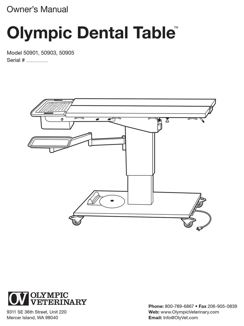
OLYMPIC VETERINARY 50901 User manual

Owner’s Manual
Olympic Dental Table
Model #50901, 50903
Serial #
9311 SE 36th Street, Unit 220
Mercer Island, WA 98040
Phone: 800-789-6867 • Fax 206-905-0839
Web: www.OlympicVeterinary.com
Email: Info@OlympicVeterinary.com
OLYMPIC
VETERINARY

2
About this Manual
This manual contains information on the setup, use and upkeep of the Olympic Dental Table and should
be read in its entirety before rst use to assure safe operation and optimal performance.
This Dental Table has a serial number you will need to reference when seeking technical support. This is
stamped on the bottom right corner of the Product Identication Label, which is located at the end of the
table top. For future reference, it is recommended you write this serial number on the front of this manual.
Table of Contents
Component Identication.................................................................................................. 3
Introduction ....................................................................................................................... 4
Safety ................................................................................................................................ 4
Unpacking and Setup ....................................................................................................... 4
Assembly
Installing the Head Support and Dental Tray ............................................................. 5
Installing the Instrument Tray ..................................................................................... 5
Quick-Start Instructions.................................................................................................... 5
Operation
Loading/Unloading Patients....................................................................................... 6
Height Adjustment...................................................................................................... 6
V-Table Dorsal Positioning Adjustment...................................................................... 6
Tie-down Cleats ......................................................................................................... 6
Table Tilt Adjustment.................................................................................................. 7
Instrument Tray Adjustment ....................................................................................... 7
Power ............................................................................................................................... 7
Moving the Dental Table ................................................................................................... 7
Cleaning ............................................................................................................................ 7
Routine Maintenance ........................................................................................................ 8
Specications.................................................................................................................... 8
Warranty............................................................................................................................ 9
Contact Us ........................................................................................................................ 9
List of Figures
Figure 1 – Component Identication................................................................................. 3
Figure 2 – Unpacking the Dental Table ............................................................................ 4

3
Component Identification
The following illustration demonstrates the key components of the Dental Table.
B
C
I
J
D
A
GF
E
L
K
P
Q
Item Description Item Description
ABraking Casters
BSwiveling Foot Switch
CMounting Platform for Compressor
DPower Strip
EPower Cord
FInstrument Tray Arm with Mounting Plate
GInstrument Tray
HTray Arm Double-Socket
ITilt Lever
JV-Positioner Lock Levers
KTie-down Cleats
LDrain Trough
MTable Top Panels
NFront Head Support Thumbscrews
ORear Head Support Thumbscrews
PRemovable Drain Pan
QDental Screen
RDrain Pan Retention Knob
SHead Support
TLift Column
Figure 1
S
R
H
T
ON
M

4
Introduction
The Olympic Dental Table is a fully adjustable dental table designed to provide better patient presentation,
save time and improve operator comfort.
The Dental Table is adjustable in four ways to meet the needs of the operator: Height adjustable from 29" to 41".
Table Top can be tilted down to a maximum of 10 degrees for drainage. Each Table Top panel can be lifted up
to 45 degrees for dorsal positioning. Instrument tray adjustable from left to right of table.
The Olympic Dental Table also has a complete, self-contained drainage system, which collects any uids from
the Table top as well as uids passing through the Dental Screen in a removable Drain Pan located under the
Head Support.
Safety
Please read and follow the instructions in this manual, including all safety instructions and precautions,
carefully and completely.
The user should be aware that the Dental Table is a powerful machine with moving parts capable of causing injury
if proper precautions are not taken. The lift is raised and lowered by means of an electrical actuator, and care
must routinely be taken to assure that hands, feet and other body parts are not in the path of the lift mechanism.
Caution: Do not use the Dental Table for patients weighing more than 250 pounds.
Unpacking and Setup
Warning: The Olympic Dental Table is heavy
and requires at least 2 people to unpack and
move in order to avoid injury to staff or damage
to the product.
Caution: Do not lift the table by grasping the
table top as this can result in permanent damage
to the unit.
Note: If you suspect concealed shipping damage,
please save all packaging and contact Olympic
Veterinary immediately at 1-800-789-6867.
1. Move the pallet to a level location as close
as possible to the intended installation site.
2. Remove the shrink wrap and the cardboard lid,
then completely peel off the cardboard shroud.
3. Cut the 2 tie-down straps securing the cardboard
carton to the table top and set the carton aside
until the table has been rolled to its nal destination.
4. The table is bolted to the oor of the pallet with
4 L-shaped brackets Asecured by 12 hex head
screws. Remove all 12 screws using the included
Hex Head Wrench.
5. Remove the 2x4 retaining board Blocated in front
of the dental table from the oor of the pallet by
sliding it out of the slotted enclosure.
E
D
A
B
C
Figure 2

5
6. Position the two included wood ramps Cin front of the dental table so that the protruding pin Dat the end
of each ramp drops into the matching hole in the oor of the pallet. Test ramp to assure it is securely attached.
7. Unlock all 4 casters Eand then slowly lower the table down the ramp until it is on level ground. It can now be
rolled to its nal destination.
8. Attach the provided components.
Assembly
Installing the Head Support and Dental Tray
1. Remove the Head Support Sfrom the inner carton. Slide its two extension arms fully onto the Head Support
mounting rails located just under the table top, then install and tighten the 4 black thumb screws to rigidly
connect the head support to the Dental Table. Care should be taken to hand tighten these thumb screws
Nand Ofully.
2. Slide the Removable Drain Pan Ponto the track beneath the funnel shaped portion of the Head Support S.
When fully engaged, the black pull knob on the right side of the Drain Pan will snap into place automatically.
3. Place the Dental Screen Qon top of the funnel shaped portion of the Head Support S.
Installing the Instrument Tray
1. Locate the two identical Instrument Tray Arms with Mounting Plate F. Insert one section into the Tray Arm
Socket H, then insert the second section into the end of the rst section. Finally, insert the 5" x 5" at
mounting plate into the top of the second section. You’ll see that the top surface of this plate is covered
in Velcro.
2. Locate the included stainless steel Size B Instrument Tray G. The bottom of this tray is covered in Velcro
and should now be pressed against the Velcro on the mounting plate to create a solid connection.
Note: The Velcro-afxed B-Tray is designed to remain permanently attached to the Dental Table and to serve
as a base on which removable B-Trays can be nested and removed for cleaning. Plastic Velcro material must be
pressed rmly to fully engage.
Note: If you ordered model #50903, you have received a second set of Instrument Tray Arms with mounting plate
and B-Tray. This assembly can be inserted in the second tray arm socket H.
Quick-Start Instructions
Note: This section is intended for use only after you have read and familiarized yourself with the entire
contents of this manual. Refer to Figure 1 for component identification.
1. Lock all 4 casters A.
2. Plug the Power Cord Einto a suitable 120V/60Hz grounded wall outlet.
3. With the table top attened and horizontal, and the table set to a comfortable height, place the patient
on the center of the table top with its head over the Head Support S.
4. Turn the Swiveling Foot switch Bto the desired location and adjust height.
5. Adjust a V-Table panel to desired angle for dorsal positioning by depressing and holding the V-Positioner
Lock Lever Jwhile raising the panel to the desired angle. Releasing the lever will lock the panel in place.
To atten a V-Positioner panel, depress and hold the lever while rmly gripping the panel, slowly lowering
the panel until level.
6. Tie patient down using the provided Tie-down Cleats.
7. The tilt of the Olympic Dental Table may be adjusted to any angle up to 10 degrees by pressing
on the Tilt Lever Iwhile simultaneously lifting or lowering the end of the table closest to the lever.
Releasing the lever will lock the table at the desired tilt angle.

6
Caution: To avoid damage to the Instrument Tray Gwhile tilting the table top down, make sure it is not
directly beneath the Removable Drain Pan P.
Caution: To prevent the table from tilting suddenly, always maintain a firm grip on the table top while
depressing the Tilt Lever.
8. Move the Instrument Tray to the desired location and place a clean instrument tray (size ‘B’) onto the
permanently installed base tray.
9. When done, empty any collected uids from the Removable Drain Pan P. To remove the pan, pull on the
Retention Knob Rwhile sliding the pan out on its track. You may also wish to remove the Drain Trough L
from under the table top for cleaning.
Operation
Loading/Unloading Patients
Caution: Be sure the Dental Table is located on a level surface and that all 4 casters are locked before
loading or unloading patients.
Caution: Do not use the Dental Table for patients weighing more than 250 pounds.
1. Press the V-Positioner Lock Levers Jand while rmly gripping the panels, slowly lower until attened.
2. Raise or lower the table top to the desired height for loading a patient by pressing and holding the indicator
on the Foot Switch B.
3. Place the patient on the center of the table with its head over the Head Support S .
4. Proceed with additional table adjustments. When a procedure is completed, the table should be returned
to a horizontal position with its 2 table V-panels attened before removing the patient.
Height Adjustment
The height of the Olympic Dental Table is innitely adjustable from 29" to 41" and may be adjusted at any time
during a procedure to provide maximum comfort to the operator or to provide better visualization or access.
The Foot Switch Bis mounted on a swivel for easy access from either side, or from the back of the table. Simply
move the swivel with your foot until the Foot Switch is directly in front of you, then step on the foot control to raise
or lower the table.
V-Table Dorsal Positioning Adjustment
The table top on your Olympic Dental Table consists of two panels, each hinged at the center of the table.
Adjust the V-Table panels to the desired angle for dorsal positioning by depressing and holding each V-Positioner
Lock Lever Jwhile raising the panel to the desired angle. Releasing the lever will lock the panel in place.
To atten a V-Positioner panel, depress and hold the lever while rmly gripping the panel, slowly lowering the
panel until level. The two panels are designed to operate independently and each can be adjusted to any angle
up to 45 degrees.
Tie-down Cleats
Mounted beneath each panel are 4 conveniently located Tie-down Cleats K.
Caution: To avoid patient sliding when table is tilted, Tie-Downs should be used.

7
Table Tilt Adjustment
The tilt of the Olympic Dental Table may be adjusted to any angle up to 10 degrees by pressing on the Tilt Lever
Iwhile simultaneously lifting or lowering the end of the table closest to the lever. Releasing the lever will lock the
table at the desired tilt angle.
Caution: To avoid damage to the instrument tray Gwhen tilting the table top, make sure the tray is not
directly beneath the Removable Drain Pan P.
Caution: To prevent the table from tilting suddenly, always maintain a firm grip on the table top while
depressing the Tilt Lever.
Instrument Tray Adjustment
The Instrument Tray travels up and down with the table top so that it is always at the same height relative
to the table surface. A double-arm design permits the user to move the tray to any desired location on either
side of the table.
The Velcro-afxed B-Tray is intended to remain in place permanently. Any standard size B-Tray will nest snuggly
in this tray and can be removed between procedures for cleaning.
Power
The Olympic Dental Table operates off suitable 120V/60Hz line voltage. A 5 port power strip with a 10' power cord
is mounted on the end of the unit under the base plate D. The lift’s motor is permanently plugged into one of
these ports. The other 4 ports are available as needed.
Moving the Dental Table
If at any time you wish to move the Dental Table, disconnect the Power Cord
E and unlock all four caster brakes.
To unlock a caster, step on the brake release lever. When the caster is locked, a red window will be visible on the
caster.
CAUTION: The Olympic Dental Table is heavy and requires at least two people to move it. Move the table
slowly and carefully.
Cleaning
Removing the trough Lfor cleaning. The trough may be removed either from the rear of the table or from
the front. To remove from the front, loosen the 4 head support thumbscrews
N and
O , tilt the head support
assembly
S down slightly, then lift the trough out of the retention clip at the rear of the unit and slide it forward.
Removing the Drain Pan P for cleaning. The Drain Pan support arms can be removed for occasional cleaning.
Unscrew and remove the 4 black knobs on both arms to remove the arms. After cleaning, replace the arms and
screw the knobs back in.
All stainless steel surfaces can be cleaned with soap and water and ordinary disinfectants.
All painted surfaces, the Base, Lift Column, and Foot Switch can be cleaned with soap and water and
ordinary disinfectant.
CAUTION: Do not let any liquid enter the Lift Column, as liquid can damage the lift mechanism
and electrical parts.
CAUTION: Make sure that knobs are cinched down as tightly as possible to prevent any movement.

8
Routine Maintenance
Stainless steel surfaces should be cleaned and dried between use to prevent iron deposit build up.
The Dental Table requires no other routine maintenance.
For any questions about the use or maintenance of the Dental Table, please call 1-800-789-6768.
Specifications
Olympic Dental Table – Model #50901, 50903
Capacity – 250 pounds with centered load V-Positioner Range – zero to 45 degrees (each side)
Table size – 21"W x 50"L Horizontal Tilt – zero to 10 degrees
Headrest size – 21"W x 12"L Casters – 4 in-line locking
Overall maximum dimensions – 21"W x 62"L x 29"H Power – 120V/60Hz
Height Range – 29" to 41" Weight – 275 pounds
Model #50901 – Olympic Dental TableTM
.1 Swivel Arm with tray.
Model #50903 – Olympic Dental TableTM
. 2 Swivel Arms with trays.

9
Contact Us
Olympic Veterinary Corporation, Customer Service
9311 SE 36th Street, Unit 220
Mercer Island, WA 98040
Phone: (800) 789-6867
Fax: (800) 905-0839
Email: info@OlympicVeterinary.com
NOTE: THIS IS NOT THE STREET ADDRESS TO BE USED FOR RMA RETURNS.
Detailed shipping instructions will be provided by customer service when a RMA is issued.
50 9 -IM-E0611G
3 year Unconditional Warranty – All Parts and Labor
Should your Olympic Dental Table, as the result of normal use, require any repair within
3 years after purchase, all replacement parts and labor will be furnished free of charge.
Other manuals for 50901
1
This manual suits for next models
1
Table of contents
Other OLYMPIC VETERINARY Medical Equipment manuals