manuals.online logo
Brands
  1. Home
  2. •
  3. Brands
  4. •
  5. Olympus Lock
  6. •
  7. Lock
  8. •
  9. Olympus Lock 720LM User manual

Olympus Lock 720LM User manual

800-525-0954 | www.olympuslock.com
[email protected] Copyright © 2020 Olympus Lock, Inc.
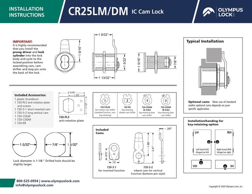
INSTALLATION
INSTRUCTIONS SFIC Cam Lock
720LM/DM
Typical Installation
Included Accessories:
1 plastic thumbturn
1 720-PL3 anti-rotation plate
and screws
1 720-3-1 short inverted cam
1 720-3-2 long vertical cam
1 720-CDLM cam shifter
1 720-CDDM cam shifter
1 720-KR cam shifter
1 725-1 6 pin core spacer
Lock diameter is 1-1/8.” Drilled hole should be
slightly larger.
720-PL3
anti-rotation plate Installation/handing for
key-retaining option
LH RH
Left-hand (LH)
Hinged on left
Right-hand (RH)
Hinged on right
VH IH
IMPORTANT:
It is highly recommended
that you install the
prong driver and lock
cylinder into the lock
body and cycle to the
locked position before
assembling cam, cam
shifter and stop pin onto
the back of the lock.
720-3-1
for inverted function
720-3-2
inbent cam for vertical
function (bottom-pin style)
Included
Cams
720-CDLM
lost motion cam shifter
(standard function, non-
key-retaining)
720-CDDM
(A Side)
key-retaining door
cam shifter
720-KR
key-retaining
drawer cam shifter
720-CDDM
(B Side)
key-retaining door
cam shifter
1233
Optional cams Note: use of standard
and/or optional cams depends on your
specific application.
720-3-3
inbent cam for
inverted function
720-3-4
3"straight cam for vertical
function
720-3-5
inbent cam for
inverted function
TR201
1/8"
TR202
1/4"
TR203
3/8"
TR204
5/32"
Optional Cams
Optional TR200 Series Trim Collars
720LM/DM — INSTALLATION INSTRUCTIONS
800-525-0954 | www.olympuslock.com | [email protected] Page 2
Trim collars pull lock forward
allowing it to be used on thinner
gauge material thickness.
Double-D metal hole punch is available
separately. Punches double-D cut out in metal.
For use with 1-1/8” diameter cam locks.
Optional Metal Punch
CL-MP-118
Metal Punch
720LM/DM — INSTALLATION INSTRUCTIONS/CAM ASSEMBLY
800-525-0954 | www.olympuslock.com | [email protected] Page 3
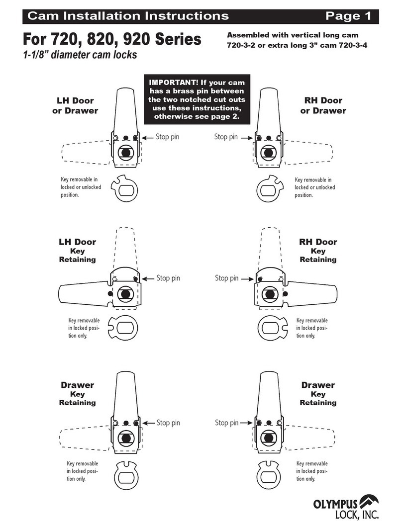
Assembled with:
Special note:
If your cam has a brass pin on the bottom of the cam use these instructions,
otherwise see page 5 for mid-pin cam assembly.
720-CDLM
lost motion cam shifter
(non-key-retaining)
720-CDDM (A Side)
key retaining door
cam shifter
720-KR
key retaining drawer
cam shifter
720-CDDM (B Side)
key retaining door
cam shifter
12 3 3
Stop
pin
Stop
pin
LH Door or
Drawer
RH Door
or Drawer
Key removable
in locked or
unlocked position.
Key removable in
locked or unlocked
position.
11
L
O
C
K
E
D
L
O
C
K
E
D
22
Stop
pin
Stop
pin
Drawer
Key
Retaining
Key removable
in locked
position only.
Drawer
Key
Retaining
Key removable
in locked
position only.
L
O
C
K
E
D
L
O
C
K
E
D
Stop
pin
Stop
pin
LH Door
Key
Retaining
Key removable
in locked
position only.
RH Door
Key
Retaining
Key removable
in locked
position only.
3 3
LOCKED LOCKED
Standard Function Cam Assembly Key-retaining Function Cam Assembly
Supplied Cam Shifters
Important:
It is highly recommended that you install the prong driver and lock
cylinder into the lock body and cycle to the locked position before as-
sembling cam, cam shifter and stop pin onto the back of the lock.
720-3-2 vertical long cam
720-3-4 extra long 3” cam STOP!These instructions are for bottom-pin style
cams only. If your cam has the brass pin in the
middle, see the instructions on PAGE 4.
720LM/DM — INSTALLATION INSTRUCTIONS/CAM ASSEMBLY
800-525-0954 | www.olympuslock.com | [email protected] Page 4
Inverted
Drawer
Key
Retaining
Key removable
in locked
position only.
LH Door
Key
Retaining
RH Door
Key
Retaining
Key removable
in locked
position only.
Key removable
in locked
position only.
2
33
Assembled with: 720-3-1 inverted short cam
720-CDLM
lost motion cam shifter
(non-key-retaining)
720-KR
key-retaining drawer
cam shifter
1
2
Stop pin
Drawer
Key removable in
locked or unlocked
position.
Drawer
Stop pin
Key removable in
locked or unlocked
position.
Stop pin
Drawer
Key
Retaining
Key removable
in locked
position only.
Drawer
Key
Retaining
Stop pin
Key removable
in locked
position only.
22
11
L
O
C
K
E
D
L
O
C
K
E
D
L
O
C
K
E
D
L
O
C
K
E
D
720-CDDM (A Side)
key-retaining door cam
shifter
720-KR
key-retaining drawer
cam shifter
720-CDDM (B Side)
key-retaining door
cam shifter
233
Key-retaining Function Cam AssemblyStandard Function Cam Assembly
Key-retaining Function Cam Assembly
720-3-3 inverted long cam
720-3-5 inverted long cam
Assembled with:
Important:
It is highly recommended that you install the prong driver and lock cylinder into the lock body and cycle to the locked
position before assembling cam, cam shifter and stop pin onto the back of the lock.
Supplied Cam Shifters
Supplied
Cam Shifters
720LM/DM — INSTALLATION INSTRUCTIONS/CAM ASSEMBLY
800-525-0954 | www.olympuslock.com | [email protected] Page 5
Stop
pin
LH Door or
Drawer
Key removable in
locked or unlocked
position.
1
L
O
C
K
E
DStop
pin
RH Door
or Drawer
Key removable in
locked or unlocked
position.
1
L
O
C
K
E
D
22
Stop
pin
Stop
pin
Stop
pin
Stop
pin
LH Door
Key
Retaining
Key removable
in locked
position only.
RH Door
Key
Retaining
Key removable
in locked
position only.
Drawer
Key
Retaining
Key removable
in locked
position only.
Drawer
Key
Retaining
Key removable
in locked
position only.
33
LOCKED
LOCKED
L
O
C
K
E
D
L
O
C
K
E
D
720-CDLM
los-motion cam shifter
(non-key-retaining)
720-CDDM (A Side)
key-retaining door
cam shifter
720-KR
key-retaining drawer
cam shifter
720-CDDM (B Side)
key-retaining door
cam shifter
12 3 3
Supplied Cam Shifters
Important:
It is highly recommended that you install the prong driver and lock
cylinder into the lock body and cycle to the locked position before as-
sembling cam, cam shifter and stop pin onto the back of the lock.
Standard Function Cam Assembly
Special note:
If your cam has a brass pin in the middle of the cam use these instructions,
otherwise see page 3 for bottom pin cam assembly.
Assembled with: 720-3-2 vertical long cam
720-3-4 extra long 3” cam
Key-retaining Function Cam Assembly
STOP!These instructions are for mid-pin style cams
only. If your cam has the brass pin on the bot-
tom, see the instructions on PAGE 2.

This manual suits for next models

1

Other Olympus Lock Lock manuals

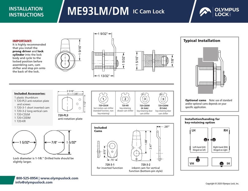
Olympus Lock ME93LM/DM User manual

Olympus Lock

Olympus Lock ME93LM/DM User manual

Olympus Lock 200DW User manual

Olympus Lock

Olympus Lock 200DW User manual

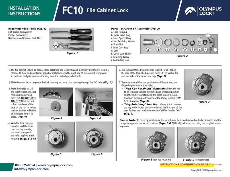
Olympus Lock FC10 User manual

Olympus Lock

Olympus Lock FC10 User manual

Olympus Lock CR25LM User manual

Olympus Lock

Olympus Lock CR25LM User manual

Olympus Lock 820S User manual

Olympus Lock

Olympus Lock 820S User manual

Olympus Lock 720 Series User manual

Olympus Lock

Olympus Lock 720 Series User manual
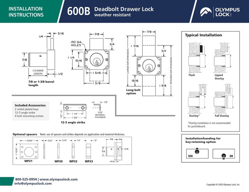
Olympus Lock 600B User manual

Olympus Lock

Olympus Lock 600B User manual
Popular Lock manuals by other brands

Hahn KT-S installation instructions

Hahn

Hahn KT-S installation instructions

Allegion AD Series manual

Allegion

Allegion AD Series manual

Yale MC182010B quick start guide

Yale

Yale MC182010B quick start guide

BASI HS 1400 installation instructions

BASI

BASI HS 1400 installation instructions

Primera SAFEHINGE JUNIOR-RHINO PR-6308-BR-LL manual

Primera

Primera SAFEHINGE JUNIOR-RHINO PR-6308-BR-LL manual

iLoq D10S Series installation instructions

iLoq

iLoq D10S Series installation instructions

Aurus PN-19RF Installation instruction

Aurus

Aurus PN-19RF Installation instruction

Lockly DUO installation guide

Lockly

Lockly DUO installation guide

Aleko LM176 user manual

Aleko

Aleko LM176 user manual

CDVI SD300 installation manual

CDVI

CDVI SD300 installation manual

SICK i15-EM0123 operating instructions

SICK

SICK i15-EM0123 operating instructions

COMPX CB-250 instruction sheet

COMPX

COMPX CB-250 instruction sheet

secureo Key Box instruction manual

secureo

secureo Key Box instruction manual

Ingersoll-Rand SCHLAGE Everest Service manual

Ingersoll-Rand

Ingersoll-Rand SCHLAGE Everest Service manual

Assa Abloy ASSA Coded 1.2 Programming instructions

Assa Abloy

Assa Abloy ASSA Coded 1.2 Programming instructions

U-tec Ultraloq UL3 installation instructions

U-tec

U-tec Ultraloq UL3 installation instructions

ELCOM 7205 Operating	 instruction

ELCOM

ELCOM 7205 Operating instruction

PDQ CLS Installation instruction

PDQ

PDQ CLS Installation instruction

manuals.online logo
manuals.online logoBrands
  • About & Mission
  • Contact us
  • Privacy Policy
  • Terms and Conditions

Copyright 2025 Manuals.Online. All Rights Reserved.