7
SPECIFICATIONS
Item Specification
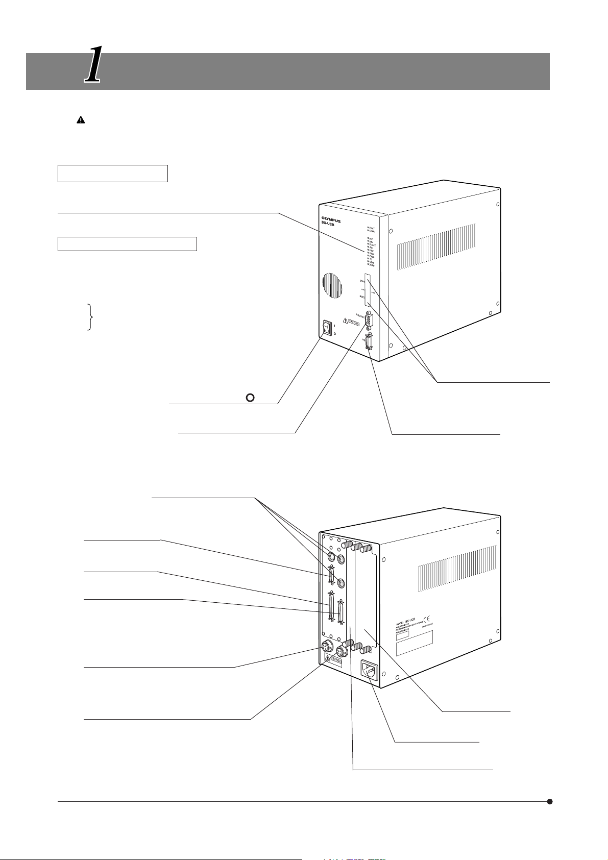
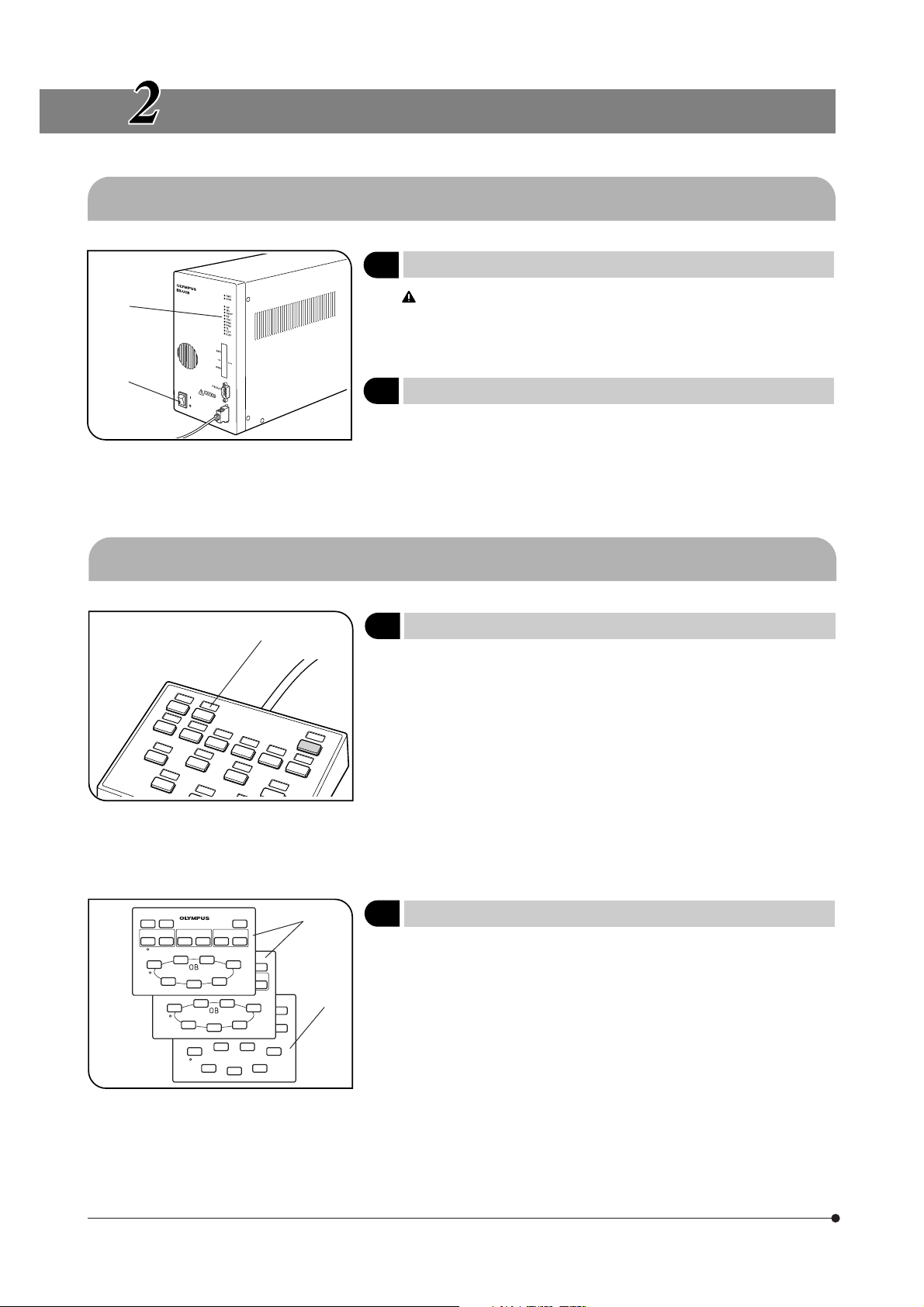
Control Box BX-UCB
Power supply rating Input rating: 100 to 120/220 to 240 V , 50/60 Hz, 3.5/1.5 A
LED indicators · RMT (Remote) LED · ERR (Error) LED
· Module connection LED x 10
Option slots Power capacity (single slot)
Per board Total of 3 slots
+5 V 1 A max. 2 A max.
+15 V 1 A 1 A (normal) + 1 A (motor load 20% duty)
+24 V 1 A max 2 A max.
Dimensions & weight 125(W) x 216(H) x 310(D) mm, approx. 5 kg (11 lb.)
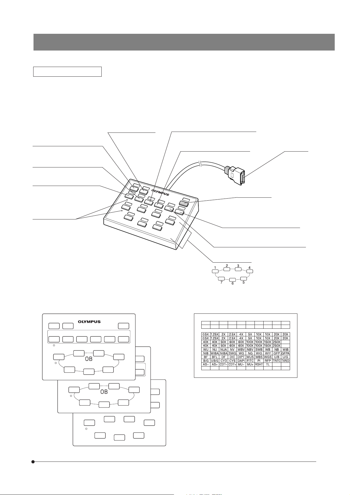
Hand Switch U-HSTR2
Button functions Connects to the BX-UCB for use in the control of following operations.
(Can also be connected to Olympus AX70, AX80 or U-REMPS but the
operation is not normal in this case.)
When a PC is not used:
· With the BX-RFAA vertical illuminator, the hand switch controls opera-
tions including the shutter release, top lens, reserve, aperture iris dia-
phragm opening/closing, turret clockwise/counterclockwise rotation,
mirror unit clockwise/counterclockwise operation and objective switch-
ing (from 7).
· With the BX-RLAA vertical illuminator, the hand switch can control op-
erations including BF, DF, reserve, aperture iris diaphragm opening/
closing and objective switching (from 7).
When a PC is used:
· Any function can be assigned from the PC.
Dimensions & weight 147 (W) x 32 (H) x 108 (D) mm., approx. 0.37 kg (0.81 lb.)
Operating environment · Indoor use.
· Altitude: Max. 2000 m.
· Ambient temperature: 10 to 35°C.
· Maximum relative humidity: 80% (up to 31°C). The maximum humidity
decreases linearly at above 31°C, through 70% (at 34°C), 60% (at 37°C)
to 50% (at 40°C).
· Supply voltage fluctuation: ±10%.
· Pollution degree: 2 (in accordance with IEC664).
· Overvoltage category: II (in accordance with IEC664).