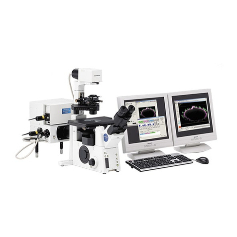
Olympus FV3000 User guide

Last updated on Mar 2022
BEGINNERS SAFETY MANUAL FOR
OLYMPUS FV3000 CONFOCAL (#02-20)
Produced by Shaalini, Graham Wright, Fiona Chia, Cris Barzaghi, Melvin
1. Safety Guidelines ...................................................................................................................2
1.1 Lasers ...............................................................................................................................2
1.2 Immersion Oil...................................................................................................................2
1.3 Metal Halide Lamps (MHL) ..............................................................................................2
2. Training ..................................................................................................................................3
2.1 To arrange a training session:..........................................................................................3
3. Online Booking and System Access........................................................................................4
3.1 Acknowledgements..........................................................................................................5
4. Operation Procedures............................................................................................................5
4.1 Switching ON Protocol .....................................................................................................5
4.2 Objective lens...................................................................................................................6
4.2 Software Initiation ...........................................................................................................7
4.3 Setting up directory to save images ................................................................................8
4.4 Laser Configuration Settings............................................................................................9
4.5 Using the LSM Imaging Tab............................................................................................10
4.6 Image Adjustments –Setting the Gain and Offset properly..........................................11
4.7 How to do a Z stack for a 3D Image (xyz).......................................................................11
4.8 For Time-lapse (xyzt)......................................................................................................12
4.9 Reuse previous settings and export images ..................................................................12
4.10 Switching OFF Protocol................................................................................................13
5. Troubleshooting...................................................................................................................14

Last updated on Mar 2022
1. Safety Guidelines
Please adhere to the safety guidelines for your own safety and health. When in doubt,
always approach the bioimaging facility for assistance.
1.1 Lasers
Lasers in the confocal facility are class 3 lasers. This means that the lasers are strong enough
to cause serious damage to your eyes, including temporary to permanent blindness.
Therefore, please always follow the safety guidelines below when using the confocal
microscopes:
•Before turning on the lasers, make sure the power connections are all connected
properly. If there are any disconnected wires, please reconnect them or inform the
facility staff. If you see any exposed wires, do not attempt to use the equipment and
inform facility staff immediately.
•For all confocal systems, there is a minimum time for lasers to be switched ON/OFF.
Please check the operation procedure for the respective microscopy system that you
are assigned to. This is to ensure the lasers have sufficient time to heat up and cool
down before running again.
•When using the lasers to image, NEVER look directly at the laser while imaging. If a
safety shutter is present, make sure it is in the correct position to better protect your
eyes.
1.2 Immersion Oil
Modern immersion oil has no known hazards to human beings so far, yet they can cause
discomfort to a person if the immersion oil has been left on skin for too long or inhaled.
Therefore, please take note of the following safety guidelines for using immersion oil:
•Use the applicator to apply the immersion oil onto the slides for upright system.
•Do not touch the applicator oil directly on the objective lens as this will scratch or
break the lens. Instead, allow the drop of oil to contact the lens surface.
•If the bottle containing immersion oil has oil on the sides, wipe down with kim wipes
and ethanol. Wash hands immediately after with soap and water.
•Wipe immersion oil off objective lenses after use using lens paper and wash hands
immediately after with soap and water.
•Always clean up any spilled oil or residue from oily slides immediately after your
session.
1.3 Metal Halide Lamps (MHL)
Metal halide lamps are fluorescence lamps that emit a visible light range of 300 –650nm,
enabling us to observe fluorescence signals such as GFP, DAPI and RFP. Metal halide lamps
contain mercury vapours that are extremely toxic to the human body. Therefore, please
take note of the following safety guidelines when working with the metal halide lamp:
•Ensure that the metal halide lamp has been off for at least 30 minutes before
switching it on. Once the lamp has been turned on, it must remain on for a minimum

Last updated on Mar 2022
of 30 minutes to allow sufficient time for it to warm up and run properly. The lamp has
an enforced cooldown of 300 seconds (5 minutes) after shutdown where the lamp
cannot be switched on until the 300 seconds is up.
•Check the timer on the power box to ensure the mercury lamp does not run past 2,000
hours. The timer indicator on this particular lamp power box blinks when the timer
crosses 1,900 hours.
•Do not look directly at the MHL when it is switched on as it can damage your eyes.
•Do not attempt to remove the light guide from the MHL, especially when it is on.
Direct emission of the MHL may set off fires.
•If there are no users in the next 30 mins, MHL must be turned off.
•Never attempt to change a bulb yourself. Please contact facility staff when you notice
that a bulb has reached between 2,000 –2,500 hours or is not functioning properly.
•Important! If you hear an explosion and see the burner indicator turn red from blue,
save your work and evacuate immediately.
2. Training
Use of confocal microscopy and the online booking system is authorized by facility staff
only. All users must attend the confocal training session conducted by the Bioimaging facility
staff before they are allowed to access the confocal system.
2.1 To arrange a training session:
•Please email Bioimaging Facility ([email protected]) for a training session.
•Fill in the necessary particulars in the form here:
http://microscopy.tll.org.sg/pages/conf_training_form.html
(E.g. Lab, PI, sample, and a brief description of your project)
•We will help you identify the most appropriate microscope for your imaging needs.
•We will then arrange training session according to your availability within a week.
•Training sessions usually last 1 - 3 hours depending on users’ previous experience.
•Users receiving training are highly encouraged to bring their own samples so that
staff can adjust trainings to your imaging needs, but if not possible, staff have their
own samples that they can work with.
Once you have completed the training session, we will grant you access to both the confocal
PC and the online booking system. Please keep in mind that only bioimaging facility
members are allowed to conduct the training. None of your lab members are allowed to
conduct the training for you.
If you need a refresher or some specific advice on anything microscopy related, please
approach any member of the Bioimaging Facility for assistance/help.
We also offer training on the various types of image analysis and image processing software
available here at TLL, including ImageJ/Fiji, Huygens and Imaris.

Last updated on Mar 2022
3. Online Booking and System Access
•Booking of all Light microscopes prior to use is COMPULSORY through microscopy
resource booking via TLL intranet (https://intranet.tll.org.sg/App/tll_intranet/booking_searches)
•Users are only allowed to book the confocal system that they have received training
on. If they wish to book other confocal system, they have to receive a separate
training.
•Users are entitled to advance bookings of up to 2 weeks. They are advised to plan their
experiments accordingly to avoid any disappointments.
•During Office Hours (Weekdays from 8.30am to 6pm)
➢Each user is entitled to a MAXIMUM of 2 bookings per system per week.
➢Users whom are trained on multiple systems are entitled to a maximum of 3
bookings per week but it has to be shared across the systems that they have
received training on.
➢Each booking must not exceed 3 hours.
➢If users have utilized all their entitled bookings for the week, “24Hr Rule” can be
applied where they can book the system in less than 24 hours in advance according
to its availability. If extra slots are booked within the 24-hour period, a note of
“24Hr Rule” should be made in the booking description.
•During Non - Office Hours (Weekdays after 6pm, Sat, Sun & Public holidays)
➢If users require more slots in a particular week, they can book on weekdays during
non-peak hours (after 6pm), on weekends (Sat and Sun) and on public holidays.
➢If extra time is required, bookings can be extended out of peak hours (E.g. 3 –
7pm).
•Bookings exceeding these limits are subjected to cancellation without prior warning.
•Simultaneous bookings of two or more different systems are not allowed. Multiple
bookings for the same system on the same day during office hours is strictly
prohibited.
•If users cannot attend a booked session for any reason, it is COMPULSORY that they
availability. If they are the last users for the day, they need to check if the system has
been switched off completely.
•If users are swapping a session with another user, they must change the booking
details accordingly.
•Under any circumstances, users are not allowed to make bookings on behalf of other
people. Users who have received training but are yet to gain access to microscopy
resource booking may approach TLL Bioimaging department for booking assistance if
they need to use it urgently.
•If a user fails to show up within the first 30 minutes of their booking, the slot is
forfeited and is free for any user to use it.
•If any users violate any of these Booking rules, users will be subjected to the 3 strikes
policy.

Last updated on Mar 2022
3.1 Acknowledgements
If you use the TLL Microscopy and Imaging facility and/or have been trained or assisted any
of the bioimaging facility members in your research, then this should be acknowledged
appropriately in your publications and presentations.
4. Operation Procedures
Every confocal system in TLL Bioimaging Facility has its specific instructional manual which
are found in every confocal rooms. Strictly adhere to the correct order of operation for all
system. Failure to do so will result in disciplinary action from the facility. Any issues
encountered during the operation of the system are advised to seek help from the
Bioimaging facility.
Modification, exchange or removal of components beyond this operational manual is strictly
prohibited and is only carried out by the manufacturer, Bioimaging facility or by experienced
users approved by bioimaging facility. During operation of laser microscopy system, do not
look into the laser beam directly as they are all Class 3b and Class 4 lasers.
4.1 Switching ON Protocol
(a) SIGN IN the Logbook and record your START-TIMING.
(b) Switch on the Master switch on the wall (1) & PC (2). Wait until windows icon pops
up.
(c) Switch on Stage controller box (3) & CBH controller (4).
(d) (Optional) Turn on the Metal Halide lamp (5), if needed.
(e) Turn on the Touch screen panel power button at the back (6) and wait for 5s to light
up.
(f) Switching ON Lasers,
•To use 405/488/561/640nm, switch on the power button on the main
combiner (7), then turn the key to “ON” (7A) and finally turn on the
individual lasers that you need.
•To use 445/514nm, switch on the power button on the sub combiner (8),
then turn the key to “ON” (8A) and finally turn on the individual lasers that
you need.
(g) (Optional) Turn on the incubator (9) if required. It takes 10-15mins to stabilize.
(h) Mount your slide onto the sample holder. If you need Live cell Imaging, turn on the
OkaLab incubator and the facility CO2(10). It takes 10mins to stabilize. If you require
help mounting the stage incubator holder onto the stage, please request help from
the TLL bioimaging department.
(i) Log in with your TLL user account and double click on “FV31S-SW” to load the
software.
1st offence
A warning will be issued along with the reminder of the rules.
2nd offence
A second warning will be issued and your respective PI will be notified.
3rd offence
Banned from using any of the facility’s microscope for 2 weeks.

Last updated on Mar 2022
(j) Load the FV31S-SW software and check if the model is “OLYMPUS IX3-SSU”. Then
click OK. Wait for complete initialization and DO NOT move any components on the
microscope during the initialization process.
a. If you are starting it at the morning of the first day of the week, check that
the turret is set to 10x objective or lower, then click “YES”. Cleaning the stage
will take some time.
b. Otherwise, click “NO” to skip cleaning.
4.2 Objective lens
Objective lens
Immersion media
1.25x/0.04 Plan Apochromat
Air
10x/0.4 U Plan Super Apochromat
Air
20x/0.75 U Plan Super Apochromat
Air
40x/1.35 U APO N 340 II
Oil (Blue Bottle)
60x/1.42 U Plan Super Apochromat
Oil (Blue Bottle)
100x/1.4 U Plan Super Apochromat
Oil (Blue Bottle)
30x/1.05 U Plan Super Apochromat
Silicon (Green Bottle)
60x/1.3 U Plan Super Apochromat II
Silicon (Green Bottle)

Last updated on Mar 2022
4.2 Software Initiation
Wait for complete initialization of microscope and Windows after logging in with your TLL
username and password.
Double click on:
(A) The HW configuration screen will appear:
Select Enable XY stage control
Click on OK and wait for complete initialization. Do
not move anything on the microscope during the
initialization process.
(B) Execution of IX3-SSU clean-up will pop up:
If you are the first user of the week: Rotate the
turret so that either the 1.25× or 10× objective is in
place. Click on YES and wait for complete
initialization. The cleaning process uses ultrasonic vibrations to dislodge dust that has
accumulated on the stage mechanism. This adds time to the initialization process. Do not
place anything on the stage mechanism until the initialization process is complete.
If you are not the first user of the week: Click on NO and wait for complete initialization. Do
not move anything on the microscope during the initialization process.
On the FV31S-SW software, press on the ocular tab to
observe the specimen using either bright field/DIC or
fluorescence mode.
•For Brightfield imaging, select Ocular>Ocular>DIA.
Select Cube turret #1: Empty
Under DIA, ON both TD shutter and Trans lamp.
Increase intensity of Trans lamp for specimen
viewing.
•For Fluorescence imaging, select Ocular > Ocular >
EPI. Select Cube turret #1: DAPI/FITC/TRITC
Select the appropriate EPI ND Filter to control the
fluorescence intensity.
Then EPI shutter: Open
※Keep it Closed until you are actively viewing your sample.

Last updated on Mar 2022
4.3 Setting up directory to save images
If this is your first time using the FV3000, you need to change your default folder away from
the Fluoview software default, which is in the C: drive.
•Go to Configuration →Preference tab →File/Folder
•Uncheck Use default folder
•Press the Browse button to change the folder to either inside the D: or E: drives.
To save an image:
•Under Acquire tab, select the folder icon to select your directory to save all your images.
•Please save in your folder. You have several different options on where you can save
your images.
➢Option 1: D: or E: →Users →shaalini (create your own folder)→BPAE
cells.oir. Do keep in mind that we will delete any images which are older than
3months. Please make sure to do a backup.
➢Option 2: In TLL //research_cmn/drive folder in your respective lab folders.
➢Option 3: In your own lab drive.
•Key in the title of your image. Subsequent images will be saved in a running sequence
no.
•Your images will be saved in *.oir proprietary format.
Important: please do not save any data on the C: drive. Images saved in C: drive will be
deleted immediately!

Last updated on Mar 2022
4.4 Laser Configuration Settings
Under PMT Setting tab, click on Dye and Detector. A list of
commercially available dyes along with its excitation and emission
values are available for selection.
1. Choose the appropriate dye.
2. Select Add.
3. It will immediately be reflected under phase 1 where each dye
will be allocated to its respective channel. A transmitted light
channel will also be shown by default.
4. Click OK.
•Under Laser ND filter: Select 10%.
※If you need more than 10% laser power you can switch
off the ND filter, but most imaging will not need that high
power of a laser.
•Set your laser power for all your channels at 1%.
•Emission range could be altered to include a broader range of
signal otherwise you could use the default settings.
•For detectors:
➢HSD: keep HV within 350-500. More than 500 will
produce intense background noise.
➢SD:keep HV within 600-800. More than 800 will
contribute to intense background noise.
Under PMT settings tab:
•Mode: Select VBF
•Average: average a given number of scans to get a
higher signal to noise ratio.
➢In Line mode the averaging will be done on a line-
by-line basis.
➢In Frame mode the averaging will be done frame-
by-frame. Drawback: slower scanning time, more
bleaching, double exposure effect if your sample
moves. Averaging of 2 times will help you to get
better quality images if you can afford to do so.
No averaging or Line averaging is recommended if you are doing live-cell imaging.
•Sequential scan: Select Line to prevent crosstalk among the fluorophores. If you select
None, simultaneously imaging is done where cross talk is prominent.
•Confocal Aperture: press Auto button to make sure pinhole size is set to optimal
confocal imaging at Airy Disk ×1. This gives the most optimum size for the thinnest
optical slice while not sacrificing imaging quality. Increasing the size of the Airy Disk from

Last updated on Mar 2022
1× gives a brighter image while making the optical slice thicker, while decreasing the size
of the Airy Disk from 1× gives a darker image while not making the optical slice thinner.
4.5 Using the LSM Imaging Tab
Under Scan Settings tab, in which you can set the parameters for your imaging:
•XY
➢Type: normally, Galvano is used. For live imaging,
resonant imaging is preferred for its fast imaging
but resolution will be lower.
➢Mode: Normally, mono-directional mode is used.
For fast imaging, roundtrip can be selected where
phase correction has to be adjusted.
➢Interlace: Normally OFF is preferred. If 2x is
selected, it would capture the image by skipping
every 2 lines of the image.
➢Speed: the slower, the better your image will be
(a higher signal: noise ratio; but it takes longer
and its more prone to photobleaching of your
sample).
➢Scan Size: the number of pixels in your image
(the more pixels the higher the resolution, to an
extent, but slower the acquisition)
➢Zoom: allows you to magnify your region of
interest, the arrows allow you to zoom images
only in the center. Ideal zoom which satisfy the Nyquist limit can be achieved by
zooming till the red arrow, any zoom beyond it will result in poor resolution and
result in more photobleaching/damage.
Click on Live (images according to your scan setting configuration)/Live 2x (2x faster
imaging)/Live 4x (4x faster imaging) to view a live image. You can now adjust parameters
while checking the result directly on the monitor. Be careful though, if you spend too long
doing this you will photo bleach and damage your sample. Start focusing your sample and
then center it moving the stage.
Now, based on the image, you can adjust the brightness using:
•Excitation laser power: The higher the laser power, the higher the risk of
photobleaching. Also, this will alter both the brightness of the fluorescent image and
that of the transmitted light detection.
•Gain: This adds computer processing to the signal from the detectors into the image to
increase/decrease its brightness. For optimum signal to noise ratio, keep at 1.00×.
•HV: Keep below 500/800 for SD/HSD detectors for a low-noise image
•Offset: adjusts the background/black level
•Pinhole: the wider the pinhole aperture, the thicker is the optical slice –which means a
blurrier, but brighter image.
Last updated on Mar 2022
There’s no general rule: these adjustments mainly depend on your sample.
4.6 Image Adjustments –Setting the Gain and Offset properly
Check image saturation level by clicking
Hi-Lo icon. The image will
change color to show red and
blue pixels. Blue indicates that the signal
in a given pixel is black, with a value of 0.
Red indicates that the signal in a given
pixel is saturated (over-exposed) with a
value of 4095.
For optimal performance, the image
needs to be so that then entire image is
set to the limits of the dynamic range.
Different sets of experiments may have
different fluorescence intensities.
Adjust the image using a combination of
the excitation Laser power, HV and Offset:
Reduce either the HV or the laser power,
until red pixels disappear. Increase Offset until a dusting of blue pixels in the background are
observed.
Click LSM start to capture an image.
4.7 How to do a Z stack for a 3D Image (xyz)
1. Under Z Series: ON for Z.
2. Select Live 2x or Live 4x to see the
specimen and click Register under origin
tab to save your focal plane where your
image is focused. After completing the Z-
stack. Move can be selected to move back
to the focal plane of focus.
3. Turn the focus knob clockwise and move all
the way to the top of your sample. Click
Register under start tab.
4. Turn the focus knob anticlockwise and move
all the way to the bottom of your sample.
Click Register under end tab.
5. With system optimized selected, the
program will determine the optimal settings
for your Z-stack. You can override these
settings using the slices or z-step size boxes.
Beware that changing these will alter the z-
resolution you attain.
1
2
3
4
5

Last updated on Mar 2022
6. Click the LSM Start button to begin the series.
4.8 For Time-lapse (xyzt)
•Under Series: ON both Z and Time.
•Register Z stack before registering
Timelapse.
•LSM Total: indicates the total time it would
take to complete your imaging according to
your Timelapse settings.
➢Cycle: is the number of times you would
like to repeat the imaging during your
timelapse experiment.
➢Interval: “FreeRun” continues to
capture images until it has completed
your selected cycle. You could always
choose an interval of your choice.
4.9 Reuse previous settings and export images
•Reusing previous Settings:
➢You can upload a configuration from a
previous image. File>Open>Image.
➢In your image tab, select the arrow
and click property where it displays a
detailed record of the settings used to
acquire the image, including its
properties. Click on the load
acquisiton parameters icon of the
image to reuse your previous image
settings.

Last updated on Mar 2022
•Export Images:
➢Right click on the image and
then export. An Export
windows will pop up.
➢Select your directory where
you would like to save your
TIFF images into.
➢Save as type: TIFF (*.tif, *.tiff)
➢Under Output format, select
RGB Color with merge and
24bit Full color.
➢Click Save.
4.10 Switching OFF Protocol
Check through TLL microscopy resource booking if there is a user immediately after you. If
there is a user immediately after you, leave the system on and log off the PC. Otherwise
switch off the system.
(a) Save your images through TLL common drive folder. Images saved in computer D/E
drives will be deleted within a month without prior warning.
(b) Lower down the objective lens completely. (Z value= 0)
(c) Remove the specimen holder with the sample and return the stage to central
position.
(d) Carefully clean the objective lens with Whatman lens tissue using 100% ethanol.
(e) Switch lens back to 10x/0.3 objective lens.
(f) Exit the FV31S-SW software and shut down PC (2).
(g) Press “OFF” on the touch screen panel and wait for 5 secs for the light to disappear.
Then, switch OFF the power button at the back of touch screen panel (6).
(h) Switch off the Stage controller box (3), CBH controller (4).
(i) Switch off the HBO/Mercury lamp if used (5). (Record down the lifespan hours in the
logbook.)
(j) Switching OFF lasers,
•To turn off 405/488/561/640nm, turn off the individual laser lines and turn the
key to “standby”, (8). Switch off the main combiner (7).
•To turn off 445/514nm, turn off the individual laser lines and turn the key to
“standby” (10). Switch off the sub combiner (9).
(k) Turn off the incubator (12) if it was on.
(l) Finally, Switch off the master switch on the wall (1).
(m) Fill in the logbook with the objective lens used.

Last updated on Mar 2022
5. Troubleshooting
Issue
Explanation & Remedial steps
No laser emission
Check:
•Laser emission switches (7, 7A, 8, 8A) for the appropriate lasers
are on.
•On the laser switch box (7A, 8A), the key to the laser is turned to
the ON position.
•Lasers are properly warmed up: Look at the back of the laser
switch box. Blinking white light means laser is still warming up,
solid white light means laser is ready for emission.
•Appropriate channel that uses the laser needed is set to emit
laser.
If all laser settings are confirmed and there is still no laser emission,
please contact Bioimaging Group.
No stage
movement
Check the coarse/fine movement setting near the focus and xy position
knobs. It is a physical button that has no electronic indication
elsewhere, whether on the TPC or the computer terminal. Press once
to shift to coarse movement.
XY stage error on
start up
Stage mechanism may be jammed.
1. Switch off the stage controller (switch 4)
2. Switch off the microscope body (switch 3)
3. Carefully move the stage by hand to all four corners.
4. Switch on the microscope body (switch 3)
5. Switch on the stage controller (switch 4)
6. Switch on the control panel (switch 6)
7. Open the FV31S-SW program
If error PROCESS_TERMINATED or LAST_OPERATION_NONCOMPLETED
occurs, acknowledge the error and restart the FV31S-SW program
again.

Last updated on Mar 2022
Stage movement is
not smooth/jerks
around
1. Switch off the stage controller
2. Manually manipulate the stage to each of the 4 corners
3. Spray compressed air to dislodge any dust particles that may be
causing issues.
4. Switch on the stage controller and restart the Fluoview
software
5. Select “Yes” when you see the popup (shown below) asking if
you want to execute the cleaning process for the stage unit.
No signal during
confocal scanning
1. Use the transmitted detector to check. If the specimen is thick
and non-transparent, the specimen should be removed to first
check for laser pass through to transmitted detector. For easier
verification, standard specimen slides can be used as
confirmation check.
2. Check to see if scanning spot can be spotted on the specimen.
3. If there is no scanning spot:
I. Check that main laser key is switched on and the
appropriate laser is switched on.
II. Check the laser rack to check the laser status light.
Blinking light on the diode laser (which indicates laser
starting up) has turned to a solid white or coloured light
(sometimes red light might be indicative of error).
III. Restart the main controller right at the bottom if none of
the steps taken work, especially if the machine has been
left on by the previous user.
Signal image not
visible/too dim
even at high laser
power
Check: If fluorescence signal is visible on wide-field eyepiece.
Check: PMT settings if fluorescence can be seen on wide-field
Ideal base settings are
•HV: 350-500V for HSD, 600-800V for SD. You can set the HV
higher for quick sample spotting, then when you find the sample
you can tune the HV lower and increase laser power.
•Gain: 1x. Decreasing Gain reduces brightness and increasing
Gain doesn’t increase the sensor’s sensitivity anyway.
•Offset: 0%. Adjust it only after you find your sample.
•Pinhole: Auto. When set to manual mode it may default to the
smallest size which will make the signal very dark.
Control panel
switches off when
Live View is
activated
This is a feature by Olympus to allow a fully dark room during imaging
that can be switched on/off when needed.
To check status, go to Configuration > Preference tab > Microscope Link
and check Turn the TPC backlight off during scanning and Turn the LED
indicator off during scanning. You can set them to your preferences.

Last updated on Mar 2022
Startup popup
error code:
TPC_LOGIN_ERROR
Connection between computer and the microscope was broken on the
computer side and cannot be recovered. Restart computer terminal.
Startup popup
error code:
LAST_OPERATION_
NONCOMPLETED
The last user did not shut down the program properly, or the program
encountered a fatal error during the previous session and the last user
closed their session without restarting the program.
•No action required. Restart the program as normal.
Other manuals for FV3000
2
Table of contents
Other Olympus Microscope manuals

Olympus
Olympus IX70 User manual

Olympus
Olympus BX61 User manual

Olympus
Olympus CKX53 User manual

Olympus
Olympus BX41 User manual

Olympus
Olympus DP74 User manual

Olympus
Olympus BXFM Series User manual

Olympus
Olympus BX-RLA2 User manual

Olympus
Olympus DP73 User manual

Olympus
Olympus SZX16 User manual

Olympus
Olympus BH2-5RE Installation instructions

Olympus
Olympus BX46 User manual

Olympus
Olympus IX73 User manual

Olympus
Olympus BX41 User manual

Olympus
Olympus CX43 User manual

Olympus
Olympus Pom User manual

Olympus
Olympus CX21LED User manual

Olympus
Olympus CX31 User manual

Olympus
Olympus U-DA User manual

Olympus
Olympus VMF Operating instructions

Olympus
Olympus CK30 User manual