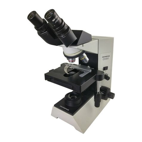
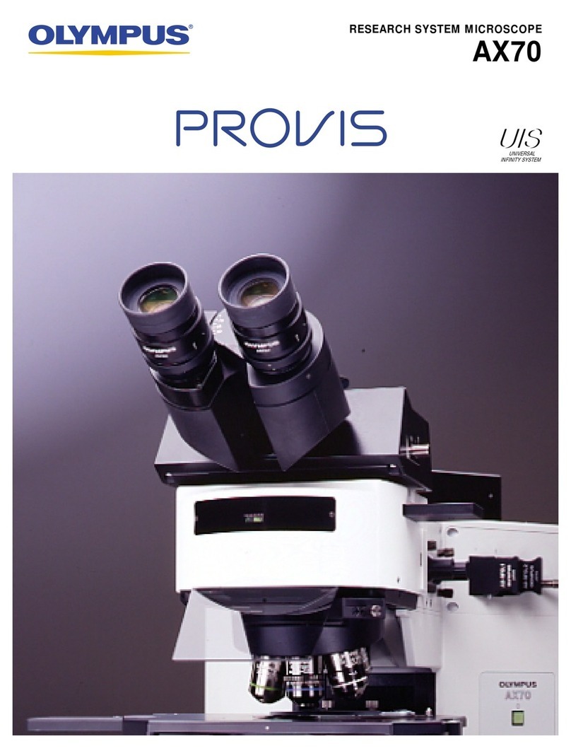
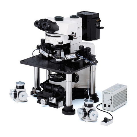
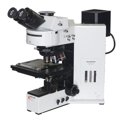
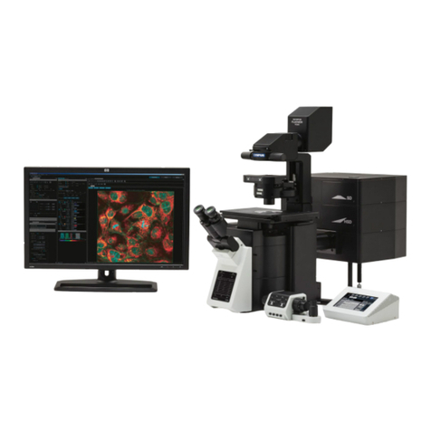
Olympus BX53M User manual

Optical Microscope and Accessory
Instructions
This instruction manual is for the system microscope model BX53M.
To ensure the safety, obtain optimum performance and to familiarize yourself fully with
the use of this system, we recommend that you study this manual thoroughly before
operating this system, and always keep this manual at hand when operating this system.
Retain this instruction manual in an easily accessible place near the work desk for future
reference.
For details of products included in the configuration of this system, see page 9.
System Microscope
BX53M

In accordance with European Directive on Waste Electrical and Electronic Equipment, this
symbol indicates that the product must not be disposed of as unsorted municipal waste, but
should be collected separately.
Refer to your local Olympus distributor in EU for return and/or collection systems available in
your country.
NOTE: This product has been tested and found to comply with the limits for a Class A digital device,
pursuant to Part 15 of the FCC Rules. These limits are designed to provide reasonable protection
against harmful interference when the product is operated in a commercial environment. This product
generates, uses, and can radiate radio frequency energy and, if not installed and used in accordance
with the instruction manual, may cause harmful interference to radio communications.
Operation of this product in a residential area is likely to cause harmful interference in which case the
user will be required to correct the interference at his own expense.
FCC WARNING: Changes or modifications not expressly approved by the party responsible for compliance
could void the user’s authority to operate the product.
This product is applied with the requirements of standard IEC/EN61326-1 concerning
electromagnetic compatibility.
- Emission Class A, applied to industrial environment requirements.
- Immunity Applied to industrial environment requirements.
Some interference may occur if this product is used in domestic location.
For Korea only

Introduction....................................................................................................................................................... 1
Safety precautions...................................................................................................................................... 2
1 Nomenclature of units........................................................................................................................ 8
2 List of combinable units ................................................................................................................... 9
3 Basic operations of the microscope (brightfield observation).....................14
3-1 Reflected light brightfield observation procedures...........................................................14
3-2 Turning ON the main switch..................................................................................................................16
3-3 Selecting the illumination.........................................................................................................................16
1Changing between the reflected light illumination and the transmitted light
illumination.......................................................................................................................................................................................16
3-4 Selecting the observation method ..................................................................................................17
1When BX3M-RLAS-S is combined.............................................................................................................................. 17
2When BX3M-KMA-S is combined................................................................................................................................ 17
3When BX3M-RLA-S is combined ................................................................................................................................. 17
4When BX3M-URAS-S is combined.............................................................................................................................18
3-5 Changing between the eyepiece light path and the camera light path ............19
3-6 Placing a sample on the stage...........................................................................................................19
1Placing a sample........................................................................................................................................................................ 19
2Adjusting the stage height.................................................................................................................................................20
3Using the Y-axis lock .............................................................................................................................................................21
4Adjusting the tension of the X-axis knob and the Y-axis knob................................................................ 21
3-7 Selecting the objective..............................................................................................................................23
3-8 Focusing................................................................................................................................................................. 24
1Moving the stage vertically................................................................................................................................................24
2Replacing the fine focusing knob ...............................................................................................................................24
3Adjusting the tension of the coarse focusing knob....................................................................................24
4Setting the movement limit with the coarse focusing knob.................................................................25
Contents

5Method to find the approximate focal point easily......................................................................................25
3-9 Adjusting the brightness ...........................................................................................................................26
1When the LED lamp housing is combined.........................................................................................................26
2When the halogen lamp housing is combined ..............................................................................................26
3When the mercury lamp housing is combined...............................................................................................26
4When the light source is combined..........................................................................................................................26
5Using the LIM/SET switch ..................................................................................................................................................27
3-10 Adjusting the observation tube......................................................................................................... 31
1Tilting adjustment ......................................................................................................................................................................31
2Using the eye shades............................................................................................................................................................31
3Adjusting the interpupillary distance........................................................................................................................32
4Adjusting the diopter...............................................................................................................................................................32
3-11 Adjusting the field diaphragm of the reflected light illumination........................34
1Using the field diaphragm (FS) ......................................................................................................................................34
2Adjusting during observation ..........................................................................................................................................35
3Centering of the field diaphragm (FS)......................................................................................................................36
3-12 Adjusting the aperture diaphragm of the reflected light illumination............. 38
1Using the aperture diaphragm (AS)...........................................................................................................................38
2Adjusting during observation ..........................................................................................................................................39
3Centering of the aperture diaphragm (AS)..........................................................................................................39
3-13 Centering the mercury burner............................................................................................................ 40
3-14 Inserting the reflected light illumination filter........................................................................42
1Using the ND filter lever........................................................................................................................................................42
2Using the filter...............................................................................................................................................................................43
3-15 Transmitted light brightfield observation procedures.................................................46
3-16 Adjusting the field diaphragm of the transmitted light illumination.................48
1Using the field diaphragm (FS) ......................................................................................................................................48
2Centering of the field diaphragm (FS)......................................................................................................................48

3-17 Inserting the transmitted light illumination filter.................................................................50
4 Various observation methods...................................................................................................52
4-1 Reflected light darkfield observation procedures.............................................................52
4-2 Reflected light simple polarization observation procedures ..................................53
4-3 Reflected light differential interference contrast (DIC) observation
procedures.............................................................................................................................................................................54
4-4 Reflected light fluorescence observation procedures..................................................55
4-5 Reflected light infrared observation procedures................................................................ 56
4-6 Reflected light simultaneous observation for BF/DF......................................................57
4-7 Transmitted light simple polarization observation procedures............................. 58
4-8 Transmitted light polarization observation procedures ...............................................59
4-9 Setting the analyzer and the polarizer of the reflected light illumination..........60
1When BX3M-URAS-S, BX3M-RLA-S or BX3M-KMA-S is combined...............................................60
2When BX3M-RLAS-S is combined..............................................................................................................................61
4-10 Inserting the DIC slider.............................................................................................................................62
1Inserting the DIC slider..........................................................................................................................................................62
2Adjusting the prism ..................................................................................................................................................................63
4-11 Opening/Closing the shutter ..............................................................................................................64
4-12 Setting the analyzer and the polarizer of the transmitted light
illumination....................................................................................................................................................... 65
1Setting the analyzer and the polarizer....................................................................................................................65
4-13 Inserting the MIX slider for reflected light observation................................................66
1Inserting the MIX slider for reflected light observation..............................................................................................66
2Turning ON the illumination of the MIX slider for reflected light observation.......................66
3Adjusting the brightness......................................................................................................................................................67
4Selecting the illumination pattern................................................................................................................................68
4-14 Using the oil immersion objective.................................................................................................. 69

5 Troubleshooting.................................................................................................................................... 70
5-1 Optical systems............................................................................................................................................... 70
5-2 Electrical systems...........................................................................................................................................74
5-3 Coarse/fine focusing ..................................................................................................................................84
5-4 Observation tube............................................................................................................................................84
5-5 Stage.........................................................................................................................................................................85
6 Specifications..........................................................................................................................................86
7 Optical performance list <<UIS2 series>> ..........................................................................89
8 Assembly.....................................................................................................................................................93
8-1 Assembly diagram ........................................................................................................................................93
8-2 Assembly procedures................................................................................................................................94
8-3 Connection with PC...................................................................................................................................121
9 Preventive inspection sheet for illumination devices .......................................123
10 Proper selection of the power supply cord ...........................................................124

1
BX53M
Introduction
This microscope employs the UIS2 (UIS) optical systems. If you use eyepiece, objective, observation tube or
condenser, etc. together with this microscope, be sure that they apply to the UIS2 (UIS) optical system series.
Using inappropriate units restricts the performance.
(There are units usable with the BX series. Contact Olympus or refer to the latest version of catalogs.)
Configuration of instruction manuals
Read all the instruction manuals provided with the units you purchased.
The following instruction manuals are prepared for the units to be used with this system.
Instruction manuals Main contents
BX53M system microscope
(this instruction manual)
Reflected light brightfield observation, reflected light darkfield
observation, reflected light simple polarization observation, reflected
light differential interference contrast observation, reflected light
fluorescence observation, reflected light infrared observation, transmitted
light brightfield observation and transmitted light simple polarization
observation
BX53/53M-P polarizing microscope Transmitted light polarization observation
BX3M-CB/CBFM
Control box/FM Control box Control box (BX3M-CB)
U-LGPS
LED and LDP light source
Connection of the light guide illumination system with the liquid light
guide, etc.
U-RFL-T power supply for mercury
burner /
U-RX-T power supply for xenon burner
Connection of the mercury lamp housing with the power supply
TH4 halogen lamp power supply unit Connection of the halogen lamp housing with the power supply
Label of the immersion oil
Read the label of the immersion oil you purchased.
Immersion oil Major contents
IMMOIL-8CC
IMMOIL-500CC
IMMOIL-F30CC
Contains the cautions and handling methods of the immersion oil.
Intended use
This product has been designed to observe magnified images of specimens in industrial applications.
Appropriate specimens can include semiconductors, electrical components, molded articles, or mechanical parts.
Industrial applications include observation, inspection or measurements.
Do not use this product for any purpose other than its intended use.

2
CAUTION - Carrying the microscope
CAUTION - Installation of the product -
Safety precautions
Hold the arm of the microscope.
When moving the microscope, hold the arm. (Approx. 15 kg)
Holding the stage, lamp housing or observation tube, etc., may
damage the microscope.
Remove the sample and the eyepiece.
When carrying the microscope, be sure to remove the sample and the
eyepieces to prevent them from dropping.
Also, remove units attached. If you carry the microscope attached with
units, the danger to drop the microscope will be increased due to the
heavier weight.
Do not slide on the top surface of the table.
Do not move the microscope by sliding on the top surface of the table.
The rubber legs may be damaged.
Install the microscope on a sturdy, level table or bench.
If you install the microscope on an unstable table or a tilted table, the microscope may drop and you may get injured.
Prevent the microscope from overturning.
The microscope becomes unstable if the height of the microscope is increased by the accessories mounted on it. In
this case, as this microscope may be overturned, take the actions to prevent the microscope from overturning.
In particular, if following units are combined, the microscope may be overturned even by the tilt of 10° or less.
· Height adapter (BX3M-ARMAD)
· Super widefield erect image tilting trinocular observation tube (U-SWETTR-5)
· Tilting trinocular tube (U-TTR-2)
· Intermediate attachment (U-DP, U-DP1XC, U-ECA, U-CA, U-EPA2, U-CPA, U-OPA, U-TRU, U-KPA)
For measures to prevent overturning, see "Attaching the overturning prevention plate" (page 94).
If the product is used in a manner not specified by this manual, the safety of the user may be imperiled. In addition, the
product may also be damaged. Always use the product according to this instruction manual.
The following symbols are used in this instruction manual.
CAUTION : Indicates a potentially hazardous situation which, if not avoided, may result in
minor or moderate injury.
NOTE
: Indicates a potentially hazardous situation which, if not avoided, may result in
damage to the product or other property.
TIP
: Indicates the useful knowledge or information for use.

3
BX53M
CAUTION - Electric safety -
Always use the power cord provided by Olympus.
If the proper AC adapter, the power cord and other cables are not used, the electric safety and the EMC (Electro-
Magnetic Compatibility) performance of the product cannot be assured. If no power cord is provided, please select the
proper power cord by referring to the section “Proper selection of the power cord” at the end of this instruction manual.
Always connect the ground terminal.
Connect the ground terminal of the power cord and that of the power outlet. If the product is not grounded, our
intended electric safety and EMC performance of the product can not be assured.
Do not use the product in close proximity to the sources of strong electromagnetic radiation.
Proper operation may be interfered. The electromagnetic environment should be evaluated prior to operation of the
product.
Remove the power cord in case of emergency.
In case of emergency, be sure to unplug the power cord from the power cord connector on the product or from the
wall power outlet.
Install the product at the location where you can reach the power cord connector or the wall power outlet at hand to
remove the power cord quickly.
CAUTION - Protection for electric shock -
Keep the power cord and cables sufficiently away from the lamp housing.
If the power cord and cables contact a hot area of the lamp housing, they could melt and cause electric shock.
Do not insert any tools or metal fragments in the air vents of the product.
Doing so could cause electric shock, ignition or failure of the product.
Do not touch the product with a wet hand.
In particular, if you touch the main switch of the power unit or the power cord with a wet hand, electric shock, ignition
or failure of the product may be caused.

4
CAUTION - Protection for injury -
Do not pull the cable with an excessive force.
If you pull the cable connected to the control box (BX3M-CB) with an excessive force, the control box may drop and
your hands may be pinched.
Be careful not to drop the glass plate.
If you are using the glass plate, be careful not to drop the glass plate. If the glass plate drops and is broken, you may
get injured by the broken pieces.
CAUTION - LED (light emitting diode) -
Do not look directly at the light from the LED light source for a long
time.
The LED built in this product is basically eye-safe. However, do not look
directly at the light from the LED lamp house for a long time, since it may
cause damage to your eyes.
If the laws or regulations for workers health and safety have been established,
follow them when using the microscope.
Do not look directly at the light coming out from the objective or the
specular reflection light from the specimen.
Do not look directly at the light coming out from the objective for a long time,
since it may cause damage to your eyes.
Do not expose your skin to the light coming out from the objective
for a long time.
If your skin is exposed to the light coming out from the objective for a long
time, you may get burned.
Do not press the micro switch of the MIX slider for reflected light
observation (U-MIXR) with your finger.
If you press the micro switch aof the MIX slider for reflected light
observation with your finger, the MIX slider for reflected light observation may
emit the light.
Do not insert the MIX slider for reflected light observation (U-MIXR)
upside down.
Do not insert the MIX slider for reflected light observation upside down.
Otherwise, the light coming out from the MIX slider for reflected light
observation enters your eyes through the eyepiece and your eyes may be
damaged.
aDo not press with your finger.

5
BX53M
CAUTION - Halogen lamp housing / Mercury lamp housing -
Confirm that the lamp is attached properly and cords are
connected properly.
Remove the power cord from the product when replacing the lamp.
To avoid electric shock hazards and burns when replacing the lamp, set the
main switch of the power supply for the light source to (OFF), then remove
the power cord from the product in advance. When you replace the lamp
immediately after use of the microscope, wait until the lamp housing and the
lamp are sufficiently cooled down.
Applicable
lamp
[For U-LH100L3, U-LH100IR]
12V100WHAL-L (made by PHILIPS Co. 7724I)
12V100WHAL (made by PHILIPS Co. 7023)
[For U-LH100HGAPO, U-LH100HG]
USH-103OL (made by Ushio Inc.)
Secure the sufficient space around the lamp housing.
The surface of the lamp housing on the back of the microscope gets very hot.
Therefore, when installing the microscope, secure the sufficient space around
the lamp housing, particularly on the top surface. After the microscope is
installed, check that the space below the lamp housing is sufficiently secured.
Do not attach the lamp housing to the mounting hole of the light
source for transmitted light illumination.
Do not attach the halogen lamp housing to the mounting hole of the light
source for transmitted light illumination by mistake. Otherwise, the cover on
the back of the microscope frame gets very hot and you may get burned.
The lifetime of the lamp housing (not lamp) is 8 years or 20,000 illumination
hours, whichever occurs first, as a guideline. For details, see "9 Preventive
inspection sheet for illumination devices" on page 123.

6
The following symbols are placed on this product.
Study the meaning of the symbols and always use the product in the safest possible manner.
Symbol Meaning
Indicates a non-specific general hazard. Follow the description given after this symbol
or in the instruction manual.
Indicates that the surface becomes hot, and should not be touched with bare hands.
It may cause burns.
Indicates high voltage. Take special care to prevent electric shock.
Indicates that the main switch is ON.
Indicates that the main switch is OFF.
Caution labels
The cautions are displayed on the portions which require special cautions during use and operation. Be sure to follow
these instructions.
Caution label
position
Reflected light illuminator for BF/DF (BX3M-RLA-S) High temperature
Coded universal reflected light illuminator (BX3M-URAS-S) High temperature
Shutter for coded universal reflected light illuminator
(BX3M-URAS-S) High temperature
DF converter (U-RCV) High temperature
100 W halogen lamp housing for IR (U-LH100IR) High temperature
100 W halogen lamp housing (U-LH100L-3) High temperature
100 W mercury lamp housing (U-LH100HG) /
100 W mercury apo lamp housing (U-LH100HGAPO)
High temperature
Electric shock
LED and LDP light source (U-LGPS) High temperature
Electric shock
Power supply (TH4-100) /
Power supply (TH4-200)
High temperature
Electric shock
ND filter (U-25ND50-2) /
ND filter (U-25ND25-2) /
ND filter (U-25ND6-2) /
Frost filter (U-25FR) /
Interference contrast filter (U-25IF550) /
L42 filter (U-25L42) /
Light balancing filter (U-25LBD) /
Yellow filter (U-25Y48) /
Empty slider (U-25) /
Light balancing amber filter (U-25LBA)
High temperature
When caution labels are dirty or peeled off, contact Olympus for replacement or inquiries.
CAUTION - Safety symbols -

7
BX53M
1. Do not leave stains or fingerprints on the lenses or filters. If they get dirty, blow away dust with a commercially
available blower and gently wipe the lens or filter with a piece of cleaning paper (or clean gauze).
Only when cleaning fingerprints and oil stains, slightly moisten a piece of cleaning paper with commercially
available absolute alcohol and wipe them off with it.
Since the absolute alcohol is highly flammable, it must be handled carefully. Be sure to keep it away
from open flames or potential sources of electrical sparks. For example, the electrical equipment that
is switched on and off may cause the ignition of a fire. Also, always use absolute alcohol only in a
well-ventilated room.
2. Wipe the portions other than lens with a dry soft cloth. If the dirt cannot be removed by dry-wiping, moisten a soft
cloth with diluted neutral detergent and wipe the dirty surface with it.
Do not use the organic solvents because they may deteriorate the coated surface or plastic parts.
3. After using the product, be sure to set the main switch to (OFF), wait until the lamp housing is cooled down
sufficiently, and keep it covered with a dust cover during storage.
4. Before disposing of this product, be sure to follow the regulations and rules of your local government. Contact
Olympus for any questions.
5. If the hour counter of the power supply shows 300 hours, set the main switch to (OFF) for safety purpose, wait 10
minutes or more and replace the lamp. (See page 110.)
The mercury burner contains high-pressure gas in the tube. If you keep using the mercury burner
exceeding its lifetime significantly, the distortion accumulates in the glass tube to cause the explosion
in rare cases.
In case that the mercury burner explodes
Follow the procedures below in case that the mercury burner explodes.
· Unplug the power cord from the outlet. Leave the place and ventilate for at least 30 minutes.
· After the burner and the lamp housing have cooled down, collect the remaining mercury with packing tape,
paper or dropper, etc.
· Seal the collected mercury and tools used completely in a nonmetallic container, and ask the waste disposer
to dispose of them.
· If there is any possibility that you have inhaled mercury steam, consult the doctor immediately and follow his/
her instructions.
6. The used mercury burner must be disposed of as the industrial waste. If you cannot dispose of it by yourself
properly, contact Olympus for assistance.
CAUTION
NOTE
NOTE
Maintenance and Storage
·This microscope is a precision instrument. Handle it with care and avoid subjecting it to a sudden or
severe impact.
·Never disassemble any part of the product. Otherwise, failure could be caused.
·Do not use this product in areas where it may be subjected to direct sunlight, high temperature and/or
humidity, dust or vibrations.
(For conditions of operating environments of this product, see "6 Specifications" on page 86.)
·Before attaching or detaching the units other than the MIX slider for reflected light observation (U-MIXR),
set the main switch of the microscope to (OFF).
NOTE
Handling Precautions

8
11Nomenclature of units
Eyepiece
Fluorescence mirror unit
Nosepiece
Objective
MIX slider / DIC slider for
reflected light observation
Stage
Condenser
Illuminator
Observation tube
Light source
for reflected light illumination
Light source
for transmitted light
illumination
Control box
Microscope frame
Hand switch
The diagram shown in this section shows the major units only. For units combinable to this product, see "2 List of
combinable units" (page 9).

9
BX53M
BX53MRF-S and BX53MTRF-S are categorized as optical microscope, other products are categorized as optical microscope accessory.
22List of combinable units
: Combination available (including units with restrictions)
: Combination prohibited
: Unnecessary for observation
Observation
method
Units
Reflected light Transmitted light
Brightfield Darkfield
Brightfield/
darkfield
simultane-
ously
Simple
polariza-
tion
Differential
interfer-
ence
contrast
Fluores-
cence Infrared Brightfield
Simple
polariza-
tion
Polariza-
tion
Microscope
frame
BX53MRF-S
BX53MTRF-S
Observation
tube
U-BI30-2
U-TBI-3
U-TR30-2
U-TR30IR
U-ETR-4
U-TTR-2
U-SWTR-3
U-SWETTR-5
U-TLU
U-TLUIR
Intermediate
attachment
U-DP
U-DP1XC
U-ECA
U-CA
U-EPA2
U-CPA
U-OPA
U-TRU
Illuminator BX3M-KMA-S
BX3M-RLA-S
BX3M-RLAS-S
BX3M-URAS-S
Illuminator
Option
U-RCV
U-LLGAD
Light
source for
reflected light
illumination
BX3M-LEDR
U-LH100HGAPO
U-LH100HG
U-LH100L-3
U-LH100IR
U-LGPS
Light source for
transmitted light
illumination
BX3M-LEDT
Power supply U-RFL-T
TH4-100
TH4-200
For details of polarization observation, refer to the instruction manual provided with the unit.

10
: Combination available (including units with restrictions)
: Combination prohibited
: Unnecessary for observation
Observation
method
Units
Reflected light Transmitted light
Brightfield Darkfield
Brightfield/
darkfield
simultane-
ously
Simple
polariza-
tion
Differential
interfer-
ence
contrast
Fluores-
cence Infrared Brightfield
Simple
polariza-
tion
Polariza-
tion
Light sources U-LLG150
U-LLG300
U-RMT
Nosepiece U-P4RE
U-P5BDRE
U-P6RE
U-5RE-2
U-D6RE
U-D6RE-ESD-2
U-D7RE
U-5BDRE
U-D5BDRE
U-D6BDRE
U-5RES-ESD
U-D5BDRES-
ESD
U-D6RES
U-D6BDRES-S
U-D7RES
U-D5BDREMC
U-D6REMC
U-D6BDREMC
BX3M-RMCBL
BD-M-AD
Stage U-SRG2
U-SRP
U-FMP
U-SP
U-SVRM
U-SVLM
U-SIC4R2
U-SIC4L2
U-SIC64

11
BX53M
: Combination available (including units with restrictions)
: Combination prohibited
: Unnecessary for observation
Observation
method
Units
Reflected light Transmitted light
Brightfield Darkfield
Brightfield/
darkfield
simultane-
ously
Simple
polariza-
tion
Differential
interfer-
ence
contrast
Fluores-
cence Infrared Brightfield
Simple
polariza-
tion
Polariza-
tion
Stage
Option
U-SHG
U-SHGT
U-HRD-4
U-HRDT-4
U-HLD-4
U-HLDT-4
U-MSSP
U-WHP2
U-MSSPG
U-MSSP4
U-WHP64
U-SPG64
U-SP64
BH2-WHR43
BH2-WHR54
BH2-WHR65
Condenser U-AC2
U-SC3
U-POC-2
U-LWCD
Slider for
reflected light
illumination
U-25ND6
U-25ND25
U-25ND50
U-25LBD
U-25IF550
U-25L42
U-25FR
U-25Y48
U-25LBA
U-BP1200IR
U-BP1100IR
U-25
Slider for
differential
interference
contrast
U-DICR
U-DICRH
U-DICRHC

12
: Combination available (including units with restrictions)
: Combination prohibited
: Unnecessary for observation
Observation
method
Units
Reflected light Transmitted light
Brightfield Darkfield
Brightfield/
darkfield
simultane-
ously
Simple
polariza-
tion
Differential
interfer-
ence
contrast
Fluores-
cence Infrared Brightfield
Simple
polariza-
tion
Polariza-
tion
MIX slider
for reflected
light
observation
U-MIXR
U-MIXRCBL
Polarizing
element
U-POT
U-AN-2
U-AN360-3
U-PO3
U-POTP3
U-AN360IR
U-POIR
U-AN360P
Compensator U-TAD
U-TP530
U-TP137
U-CSE
U-CBE
U-CTB
U-CWE2
U-CBR1
U-CBR2
Filter slider 43IF550-W45
45-IF546
Mirror unit U-FF
U-FBF
U-FDF
U-FBFL
U-FWBS
U-FWGS
U-FWUS
U-FDICR

13
BX53M
: Combination available (including units with restrictions)
: Combination prohibited
: Unnecessary for observation
Observation
method
Units
Reflected light Transmitted light
Brightfield Darkfield
Brightfield/
darkfield
simultane-
ously
Simple
polariza-
tion
Differential
interfer-
ence
contrast
Fluores-
cence Infrared Brightfield
Simple
polariza-
tion
Polariza-
tion
Camera
adapter
U-TV0.25XC
U-TV0.35XC-2
U-TV0.5XC-3
U-TV0.63XC
U-TV1XC
U-TV1X-2
U-CMAD3
Hand switch BX3M-HS
U-HSEXP
BX3M-HSRE
TH4-HS
Control box BX3M-CB
Eyepiece WHN10X
WHN10X-H
CROSSWHN10X
SWH10X-H
Objective Refer to "7 Optical performance list <<UIS2 series>>" (page 89).
Other optional
units
U-FC
BX3-ARM
BX3M-ARMAD
U-PJ
(orientation
plate)
DSX-CALS-HR

14
33Basic operations of the microscope (brightfield observation)
This section describes the operating procedures of the reflected light brightfield observation and the transmitted light
brightfield observation, which is the basis of observation methods. The reflected light simple polarization observation and
the reflected light differential interference contrast observation, etc. are described in "4 Various observation methods".
Remove the analyzer, polarizer or
filters from the light path.
Observation method selector knob of the
reflected light illuminator (page 17)
Select the light path. (Trinocular tube only)
4
Turn ON the main switch.
1
Light path selection lever of the trinocular
tube (page 19)
Main switch (page 16)
Stage plate (page 19)
X-axis / Y-axis knob of the stage (page 19)
Nosepiece (page 23)
Coarse / Fine focusing knob of the
microscope frame (page 24)
Brightness control knob of the microscope
frame (page 26)
Brightness control knob of the microscope
frame (page 26)
Binocular tube (page 32)
Diopter adjustment ring (page 32)
Nosepiece (page 23)
Coarse / Fine focusing knob of the
microscope frame (page 24)
Aperture diaphragm knob of the reflected
light illuminator (page 39)
Field diaphragm knob of the reflected light
illuminator (page 36)
Select the brightfield (BF) observation.
3
Place a sample on the stage.
5
Engage the 10X objective in the light path.
6
Bring the sample into focus.
7
Adjust the interpupillary distance.
Adjust the diopter.
9
10
Adjust the brightness.
8
Engage the objective with the magnification to be used in
the light path and bring the sample into focus.
12
Adjust the aperture diaphragm and the field diaphragm.
11
Adjust the brightness.
13
3-1 Reflected light brightfield observation procedures
Start observation.
Transmitted/reflected light switch (page 16)
Select the reflected light illumination
2
Table of contents
Other Olympus Microscope manuals

Olympus
Olympus CK2 User manual

Olympus
Olympus FLUOVIEW FV300 User manual

Olympus
Olympus CX41 User manual

Olympus
Olympus CX21LED User manual

Olympus
Olympus CHA User manual

Olympus
Olympus CH10 Operating instructions

Olympus
Olympus BX61WI User manual

Olympus
Olympus Fluoview FV1000 User manual

Olympus
Olympus BX60 User manual

Olympus
Olympus MVX10 User manual

Olympus
Olympus BX43 User manual

Olympus
Olympus SZX10 User manual

Olympus
Olympus BX41 User manual

Olympus
Olympus BX53-P User manual

Olympus
Olympus BX63 User manual

Olympus
Olympus BX-FLA User manual

Olympus
Olympus IMT-2-11 User manual

Olympus
Olympus BHT User manual

Olympus
Olympus CX31 User manual

Olympus
Olympus CHS User manual