Parte 6
8 17
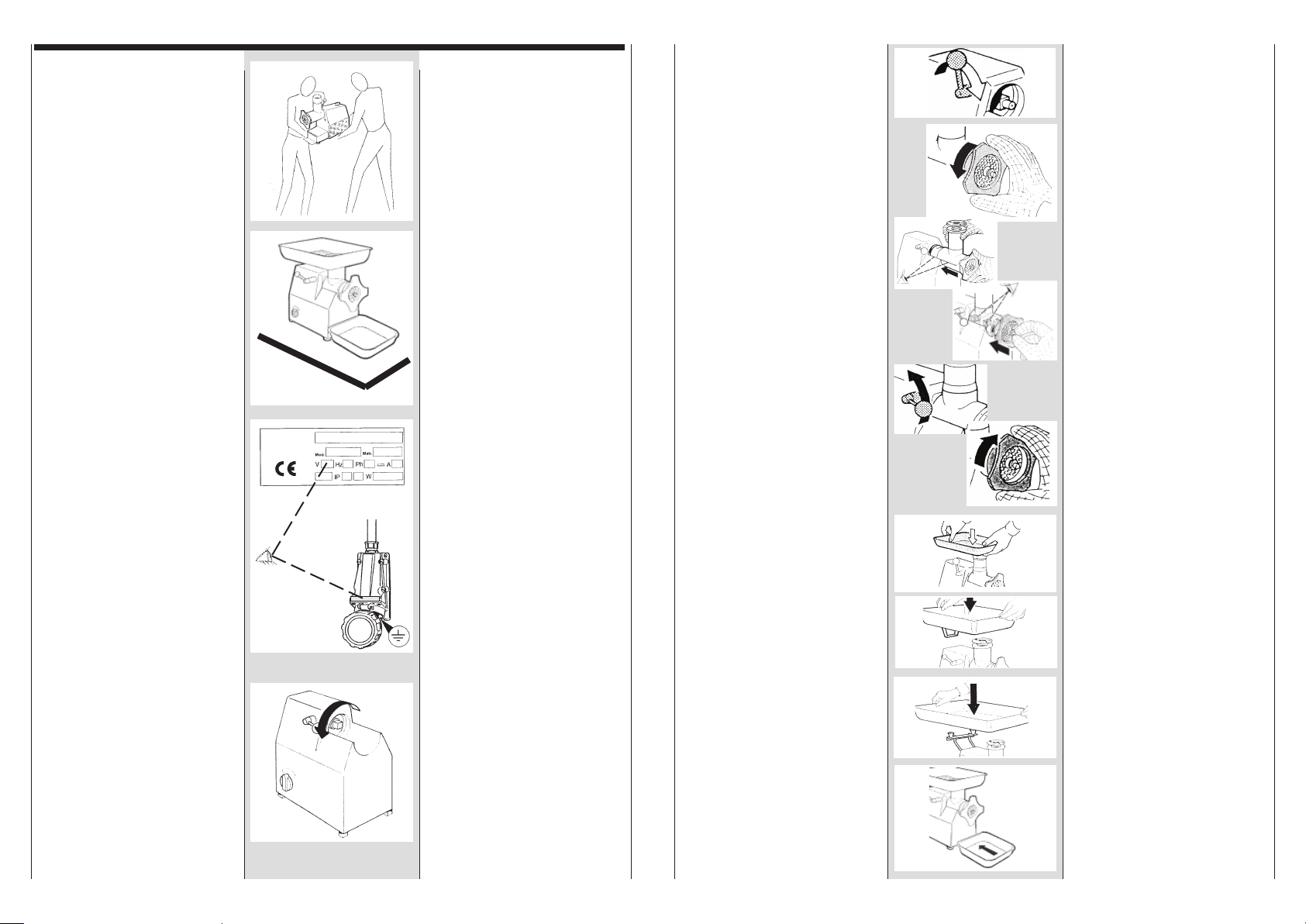
5 Controllare che l’interrutto-
re sia posizionato su 0
6 Scollegare la macchina
dalla presa di corrente
IMPORTANTE
Pulizia preliminare: termi-
nato il controllo del senso di
rotazione, pulire la macchina
dall’olio di protezione.
Riassemblare i componenti
seguendo le istruzioni nella
page 17.
-All’interno del motore é in-
serito un dispositivo di sicu-
rezza termico, di protezione
contro le sovratemperature.
TS 32E con motore mo-
nofase
-La macchina monofase uti-
lizza un interruttore di avvia-
mento con una condizione di
instabilità “Start”.
Per un corretto avviamento
si deve ruotare l’interruttore
sulla posizione “Start” e dopo
pochi secondi, rilasciare l’in-
terruttore.
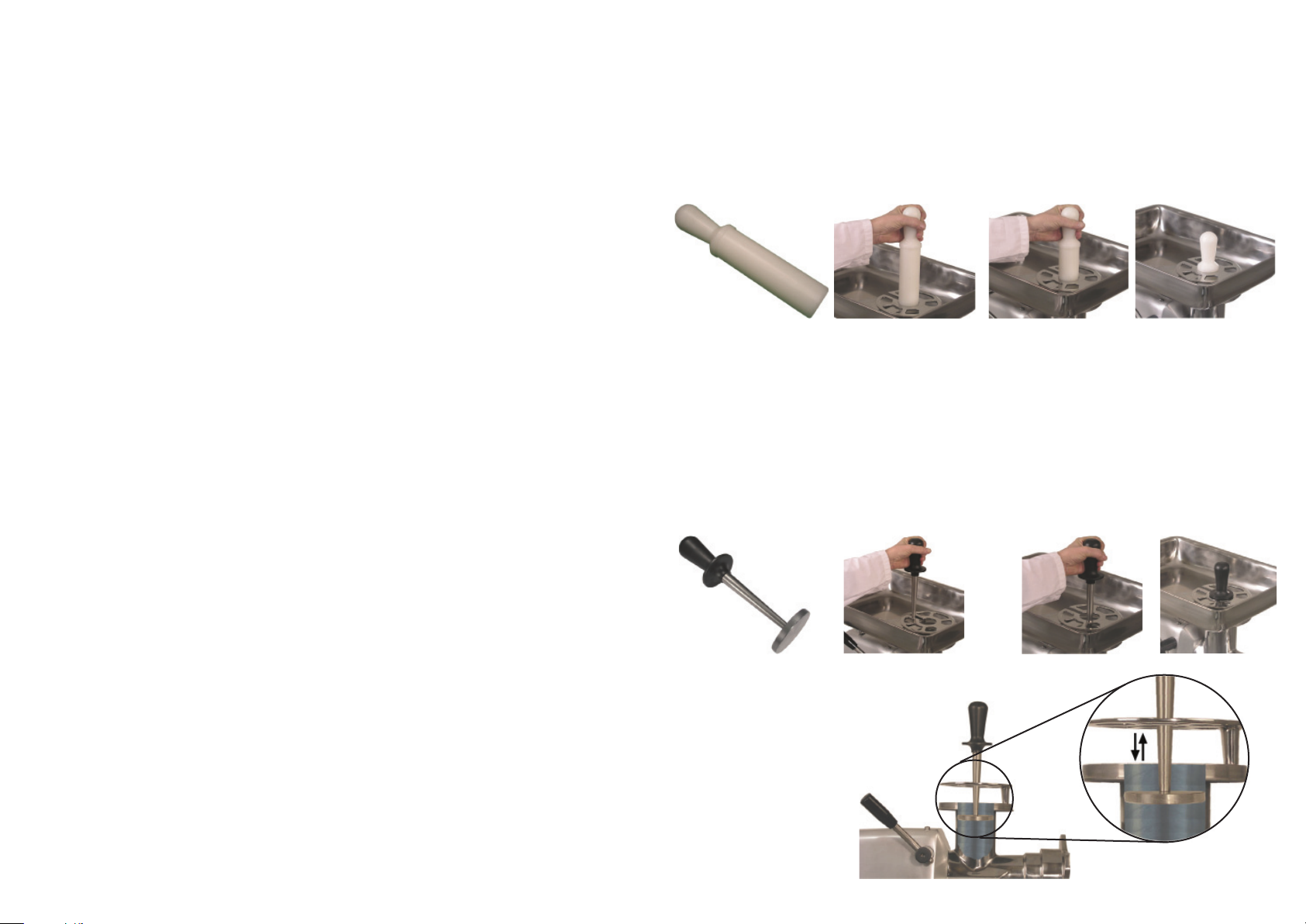
STOP
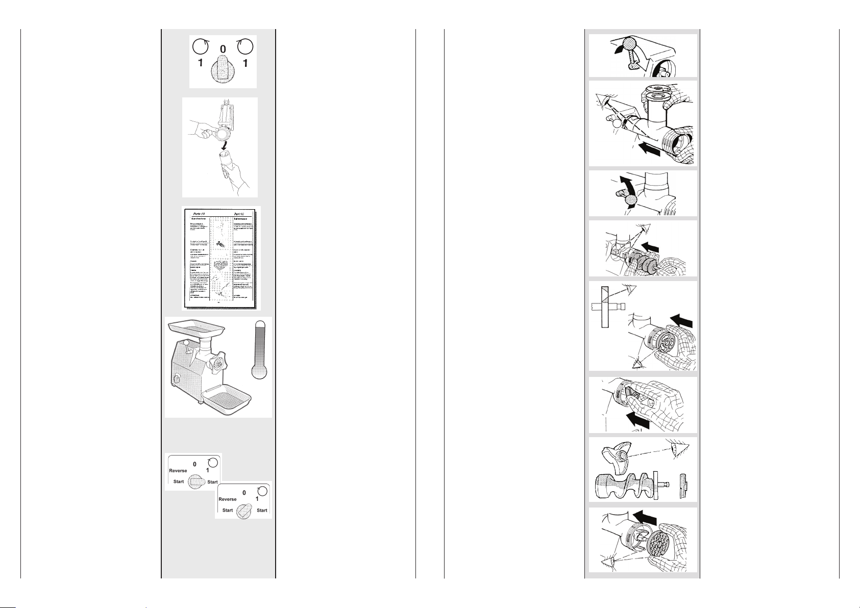
Parte 9
Montaggio gruppo
taglio a 2-3 passaggi
1 Ruotare, in senso orario sino
a fine corsa, l’impugnatura di
bloccaggio del gruppo taglio.
2 Tenere il gruppo di macina-
zione con due mani, appog-
giarlo al corpo mac-
china e spingerlo a fon-
do nella propria sede.
3 Ruotare in senso antiorario,
l’impugnatura di bloccaggio
sino ad ottenere il blocco
del gruppo di macinazione.
4 Prendere con due mani
l’elica di lavoro ed infilarla
nel gruppo di macinazione
5 Assicurarsi che la sede qua-
drata dell’elica di lavoro
coincida con il perno quadra-
to di trascinamento, infilare
l’elica di lavoro all’interno del
gruppo di macinazione.
6Montare la prima piastra
(sgrossatrice) infilandola sul
perno dell’elica, facendo
attenzione che la parte ta-
gliente dei fori sia verso
l’esterno.
7Montare il coltello a doppio
tagliente sul perno dell’elica
con il codolo rivolto verso
l’esterno.
ATTENZIONE: IL CODOLO
DEL COLTELLO DEVE ES-
SERE RIVOLTO VERSO
L’ESTERNO. PERICOLO DI
GRAVE DANNEGGIAMEN-
TO ALLA MACCHINA SE IL
COLTELLO VIENE MONTATO
AL CONTRARIO (CODO-
LO VERSO L’INTERNO).
8Montare la seconda piastra,
infilandola sul codolo del col-
tello e facendo coincidere la
tacca con la spina di riferi-
mento del gruppo di macina-
zione.
IMPORTANTE: Nel caso di
gruppo taglio a 2 passaggi,
proseguire dal punto 11
Part 6
5 Make sure that the switch
is positioned to 0
6 Disconnected the machine
from the electric supply.
IMPORTANTE
Preliminary cleaning: once
checked the rotation direc-
tion, clean the machine, by
removing the protecting oil.
Reassemble the compo-
nents, by following the in-
structions given on pag.17.
-The motor is fitted with a
thermic safety device as a
protection against excess
temperature
TS 32E with single pha-
se motor
-The single phase machine
has a start switch with a con-
dition of instability “Start”.
For a correct start you must
rotate the switch to “Start”
and after a few seconds rele-
ase the switch.
Part 9
Assembling 2-3 cut
cutting unit
1 Turn clockwise the handle
of the cutting unit to the
end of the stroke.
2 With both your hands insert
the worm casing into the
machine and push it in.
3 Turn counterclockwisethe
handle of the cutting unit
to lock the worm casing.
4 With both your hands insert
the worm into the worm
casing
5 Making sure that the square
drive on the worm seats is
positioned on the drive pin,
insert the worm into the
worm casing.
6Fit the first hole plate (large
hole plate) inserting it into
the worm shaft.
Make sure that the cutting
side of the holes are poin-
ting outwards.
7Fitt the double edged knives
on the worm shaft with the
tang pointing outwards.
ATTENTION: THE TANG ON
THE KNIVES MUST POINT
OUTWARDS. THERE IS A
RISK THAT THE MACHINE
MAY BE DAMAGED IF THE
KNIVES ARE FITTED THE
OTHER WAY ROUND
(TANG INWARDS).
8 Fitt the second hole plate
inserting it on the tang of
the knife ensuring that the
notch is aligned with the
reference pin on the worm
casing.
IMPORTANT
In case of double cutting
set,continue from point 11.