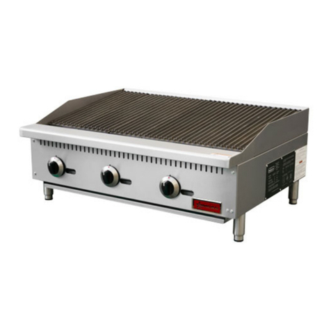
Omcan OGH-12 User manual

Gas Countertop Hot Plates
Models OGH-12 / OGH-24 / OGH-36
Instruction Manual
1-800-465-0234
www.omcan.com
3115 Pepper Mill Court, Mississauga, ON, L5L 4X5
1889 Maryland Avenue, Niagara Falls, NY, 14305
Version 1

2
Page
-------------------------------------------------------------------------------- 3
---------------------------------------------------------------------------------- 3
---------------------------------------------------------------------- 4 - 6
--------------------------------------------------------------------------------------- 7 - 8
----------------------------------------------------------------------------------------- 8 - 9
----------------------------------------------------------------------------------------- 9
------------------------------------------------------- 10 - 13
---------------------------------------------------------------------------- 14 - 15
---------------------------------------------------------------------------- 17
Table of Contents
Section
General Information
Safety & Warranty
Technical Specications
Installation
Operation
Maintenance
Instructions for Field Conversion
Parts Breakdown
Warranty Registration
Models OGH-12 / OGH-24 / OGH-36

3
General Information
Safety & Warranty
WARNINGS
• Donotstoreorusegasolineorotherammablevaporsorliquidsinthevicinityofthisoranyother
equipment.
• Improperinstallation,adjustment,alteration,serviceormaintenancecancausepropertydamage,injuryor
death.
• Readtheinstallationandmaintenanceinstructionsthoroughlybeforeinstallingorservicingthisequipment.
• Havetheequipmentinstalledbyaqualiedinstallerinaccordancewithallfederal,stateandlocalcodes.
• Donotinstallorusewithoutall4legs.
• Thisequipmentisforuseinnon-combustiblelocationsonly.
• Donotobstructtheowofcombustionandventilationair.
• Donotspraycontrolsortheoutsideoftheequipmentwithliquidsorcleaningagents.
• Allowforhotpartstocoolbeforecleaningormoving.
• Thisequipmentshouldonlybeusedinaat,levelposition.
• Donotoperateunattended.
• Anyloosedirtormetalparticlesthatareallowedtoenterthegaslinesonthisequipmentwilldamagethe
valveandaffectitsoperation.
• Ifyousmellgas,followtheinstructionsprovidedbythegassupplier.Donottouchanyelectricalswitch;do
nottrytolighttheburner;donotuseatelephonewithincloseproximity.
• Neverattempttomovegrateswhilecooking.
1 YEAR WARRANTY
WARNING:
Thepackagingcomponentsareclassiedasnormalsolidurbanwasteandcanthereforebedisposedof
withoutdifculty.In any case, for suitable recycling, we suggest disposing of the products separately
(differentiated waste) according to the current norms.
DO NOT DISCARD ANY PACKAGING MATERIALS IN THE ENVIRONMENT!
Omcan Manufacturing and Distributing Company Inc. and Food Machinery Of America, Inc. dba Omcan
are not responsible for any harm or injury caused due to any person’s improper or negligent use of
this equipment. The product shall only be operated by someone over the age of 18, of sound mind, and
not under the inuence of any drugs or alcohol, who has been trained in the correct operation of this
machine, and is wearing authorized, proper safety clothing. Any modication to the machine voids any
warranty, and may cause harm to individuals using the machine or in the vicinity of the machine while
in operation.
Thismanualcontainsimportantinformationregardingyourgascountertophotplateunit.Pleasereadthe
manualthoroughlypriortoequipmentset-up,operationandmaintenance.Failuretocomplywithregular
maintenanceguidelinesoutlinedinthismanualmayvoidthewarranty.PLEASEREAD!!!

4
Technical Specications
STANDARD FEATURES
• Stainlesssteelfrontbullnosedesignandsideconstructionthat’sfullyweldedforextradurability.
• 25,000BTUperburner.
• Twocastironburnersevery12”gratewidth.
• 4”-5”adjustablelegs.
• Separategasvalvesforeachburnerwithonepilotlightperburner.
• Removablestainlesssteeldriptrayforeasycleaning.
• 3/4”rearNPTgasinlet.
• ETLListedandETLSanitation.
Figure 1 Features and Controls
A)LEGS.Supportstheequipment.
B)ADJUSTABLEFEET.Usedtoadjusttheleveloftheequipment.
C)DRIPTRAY.Atraythatcollectsgreaseandoil.Thistraycanberemovedforcleaning.
D)PILOTLIGHTACCESSHOLE.Allowsaccesstothepilotlight.
E)GASCONTROLKNOB.Usedtosetoradjustthetemperatureofthegrillingsurface.
F)HOTPLATE.Cookingsurface.

5
Technical Specications
Model Description Burners BTU/hr Gas Type
OGH-12 GasHotPlate12” 250,000 NaturalorLPG*
OGH-24 GasHotPlate24” 4 100,000 NaturalorLPG*
OGH-36 GasHotPlate36” 6 150,000 NaturalorLPG*
Model A” Burners
OGH-12 12 2
OGH-24 24 4
OGH-36 26 6

6
Technical Specications

7
Installation
INSTALLATION TO BE DONE BY LICENSED PROFESSIONALS ONLY.
SET UP
1. Removeallpackingmaterialandtape,aswellasanyprotectiveplasticfromtheequipment.
2. Placetheequipmentinthedesiredpositionandheight.
3. Installthefour(4)legsontotheequipment.
4. Cleananddrytheequipmentthoroughlybeforeusing.
INSTALLATION
Theinstallationofthisequipmentmustconformwithlocalcodes,orwiththeNationalGasCode,ANSIZ223.1/
NFPA54,ortheNaturalGasandPropaneInstallationCode,CSAB149.1,asapplicable.
• Theequipmentanditsindividualshutoffvalvemustbedisconnectedfromthegassupplypipingsystem
duringanypressuretestingofthatsystemattestpressuresinexcessof½psi(3.5kPa).
• Theequipmentmustbeisolatedfromthegassupplypipingsystembyclosingitsindividualmanualshutoff
valveduringanypressuretestingofthegassupplypipingsystemattestpressuresequaltoorlessthen½
psi(3.5kPa).
CLEARANCE AND POSITIONING AROUND THE EQUIPMENT
• Thisequipmentmustbeinstalledadjacenttonon-combustiblesurfacesonlywithaminimumspacingof6”
fromallsides.Thisequipmentmustbeadistanceof6”fromotherequipment.Theequipmentmusthave
the4”legsinstalledandbeplacedonanon-combustiblesurface.
AIR SUPPLY AND VENTILATION
• Theareainfrontandaroundtheequipmentmustbekeptcleartoavoidanyobstructionoftheowof
combustionandventilationair.
• Adequateclearancemustbemaintainedatalltimesinfrontofandatthesidesoftheequipmentfor
servicingandproperventilation.
PRESSURE REGULATOR
• Allcommercialcookingequipmentmusthaveapressureregulatorontheincomingservicelineforsafeand
efcientoperation.TheregulatorprovidedforthisequipmentisadaptableforbothNaturalgasandLPgas.
• Regulatorspecications:¾”NPTinletandoutlet,factoryadjustedfor5”WCNaturalGasstandardandmay
beconvertedbyqualiedpersonneltobeusedforPropaneat10”WC.
Priortoconnectingtheregulator,checkthe
incominglinepressure.Theregulatorcanonly
withstandamaximumpressureof½PSI(14”
WC).Ifthelinepressureisbeyondthislimit,a
stepdownregulatorprovidedwillberequired.
Thearrowonthebottomshowsgasow
directionandshouldpointdownstreamtothe
equipment.

8
Installation
Operation
GAS CONVERSION (SEE PAGE 10)
• ConversionfromNaturalGastoLiquidPropane(LP)orviceversamayonlybeperformedbythefactoryor
itsauthorizedserviceagent.Incaseoftroubleshooting,ensurethecorrectoricesizesofthespudshave
beenprovided.
• NaturalGasOriceis#42.
• LiquidPropaneGasOriceis#53.
• Oricesizeismarkedonthespud.
LIGHTING THE PILOT
Themanifoldunitsareequippedwithstandingpilotsandeachshouldbelitimmediatelyafterthegasis
suppliedtotheequipment.
1. Beforeattemptingtolightthepilots,turnoffthemaingasvalvetotheequipmentandwait5minutesto
clearthegas.
2. Turnoffallgascontrolknobs.
3. Turnoncontrolvalveandlightallpilots.
4. Thepilotburnermustbelitattheendofthetube.Holdanignitionsourcethroughthepilotlightholeinthe
frontpanelatthepilottube.Whentheameignitesremoveignitionsource.
5. Turnoffthemaingasvalvetoshutdowntheequipment.
Smokeappearingoninitialuseoftheequipmentisnormal.Thisisaresultoftherustpreventativecoating
burningoff.Allowtheequipmentto“burnin”foratleast15minutesbeforetherstuse.
PILOT FLAME REGULATION
• Thepilotameontheequipmenthasbeenfactoryadjusted.Whenadjustmentisnecessary,adjustthepilot
amesassmallaspossiblebuthighenoughtolighttheburner.Thenimmediatelyturntheburnervalveto
thehighestsetting.Accesstothepilotameadjustmentscrewisobtainedbyremovingthefrontpanel.
BURNER ADJUSTMENT
• Removethefrontpaneltogainaccess.Turnburnervalveknobtohighestsetting.Slowlydecreasemixing
ringaperturetogiveasoftblueamehavingluminoustips.Thenslowlyincreaseopeningtoapointwhere
theyellowtipsdisappearandahardblueameisobtained.
Beforeinitialuse,turnthegascontrolknobtothemaximumsettingandallowtheequipmenttoburn-infor15
minutes.Seeingsmokecomingfromthecookingsurfaceisnormalduringburn-in.After15minutesofburn-in,
equipmentisreadyforuse.
1. Holdthelegandrotatetheadjustablefeetsotheequipmentislevel.
2. Setthegrillgratestothefulltiltpositiontostart.Thiswillallowgreasetorundownthegratesandintothe
driptraytoreduceare-ups.
3. Checkthedriptrayfrequentlyandaddwaterasnecessary.
4. Toignitetheburners,pressandturnthegascontrolknobtohighposition.
5. Allowtheequipmenttopre-heatbeforeattemptingtouse.

9
Operation
Maintenance
6. Adjustthevalveset-pointtoobtainthedesiredlevelofheat.
7. Toadjustthegrillgrate(s),raiseorlowerthebackofthegrates.Turnunitoffandallowthegrillgrate(s)to
cool.Makesuretousepotholdersorovenglovestoreposition.
• Aqualiedservicecompanyshouldchecktheunitforsafeandefcientoperationonanannualbasis.
• Gaspipingshallbeacertainsizeandinstalledtoprovideasupplyofgassufcienttomeetthefullgas
inputoftheequipment.
• Amanualshutoffvalveshouldbeinstalledupstreamfromthemanifoldwithin4ft.(1.2m)oftheequipment
andinapositionwhereitcanbereachedintheeventofanemergency.
• Checkentiregaspipingsystemforleakseverysooften.Usingagasleakdetectororsoapywatersolution
isrecommended.
• Installequipmentunderefcientexhausthoodwithameprooflterswithadistanceofnolessthan4feet
betweenthetopoftheequipmentandtheltersoranyothercombustiblematerials.
CLEANING
Tomaintaintheappearanceandincreasetheservicelife,cleanyourequipmentdaily.DONOTclean
equipmentwithsteelwool.
1. Allowtheequipmenttocoolcompletelybeforecleaning.
2. Usingawirebrush,scrapethegrillgrate(s)toremoveanyfoodresidue.
3. Tocleanequipment,useeitheradampcloth,spongewithsoapywaterorametalscraper.
4. Drygratesthoroughlytopreventrusting.
5. Emptyandcleanthedriptray.

10
Instructions for Field Conversion
MANDATORY MARKINGS
Thefollowingareexamplesoftheratingplatesthatmustbexedtotherearoftheunitoncompletionofthe
conversionbytheinstaller.

11
Instructions for Field Conversion

12
Instructions for Field Conversion
Thisinstructioncoversthefollowingmodels:
Countertopgashotplate
OGH-12/OGH-24/OGH-36
Pleaserefertospecicinstructionsforeachmodelrange.
WARNING
Improperinstallation,adjustment,alteration,serviceormaintenancecancausepropertydamage,injuryor
death.Readtheinstallation,operatingandmaintenanceinstructionsthoroughlybeforeinstallingorservicing
equipment.
WARNING
Thisconversionkitshallbeinstalledbyaqualiedserviceagencyinaccordancewiththemanufacturer’s
instructionsandallapplicablecodesandrequirementsoftheauthorityhavingjurisdiction.Iftheinformation
intheseinstructionsisnotfollowedexactly,are,anexplosionorproductionofcarbonmonoxidemayresult
causingpropertydamage,personalinjuryorlossoflife.Thequaliedserviceagencyisresponsibleforthe
properinstallationofthiskit.Theinstallationisnotproperandcompleteuntiltheoperationoftheconverted
applianceischeckedasspeciedinthemanufacturer’sinstructionssuppliedwiththekit.
MODELS PARTSINCLUDED
OGH-12 2×Jet#53drill
1×installationplate
OGH-24 4×Jet#53drill
1×Installationplate
OGH-36 6×Jet#53drill
1×installationplate
CAUTION: ENSURE THE GAS SUPPLY IS SHUT OFF AT THE MANUAL SHUT OFF VALVE BEFORE
PROCEEDING WITH THE CONVERSION.
1. Switchoffthegasatthemainsupplyvalveandallowtheunittocooldownbeforecommencingwiththe
conversion.
2. Liftoffthecompletegrateplateassemblytoexposetheburnersandvalves.
3. Removetheburnersbylooseningthefasteningnutslocatedundertherearoftheburner,lifttherearofthe
burnerandslidebackwards.
4. Thebrassoricelocatedontheendofthecontrolvalvemaynowbeloosenedandremovedusinga1/2”
wrench.
5. Replacewiththeneworicefromtheconversionkit,rstapplyingasmallamountofjointingpastetothe
threadontheendofthevalve,thiswillensureagoodgastightseal.
6. ReplacetheburnerbyslidingtheopenendovertheoriceandthenlocatingtheM5studthroughtheslot
inthesupportbracket.SecurebyreplacingtheM5nut.
7. TooperatewithLPgas,theregulatormustbechangedtooperateat10”WC(seeFig.1).Todothis
removetheconvertercapandpinfromtheregulator,removethepinandinvertthenreinstallinthecap.

13
Instructions for Field Conversion
Replacethecapontheregulatortakingcarethatthegasketisinplaceonthecap.
8. Priortoconnectingtheregulator,checktheincominglinepressure,astheregulatorscanonlywithstanda
maximumpressureof1/2PSI(13”WC).Ifthelinepressureisbeyondthislimit,astepdownregulatorwill
berequired.Thearrowforgedintothebottomoftheregulatorbodyshowsgasowdirection,andshould
pointdownstreamtotheappliance.
9. Checkforgasleaksregularly.Asoapywatersolutionisrecommendedforlocatinggasleakage.Matches,
candleameorothersourcesofignitionshallnotbeusedforthispurpose.
10.Replacetheloosettinggrateplateassemblyintoposition.
11.Fixtheconversionratingplatesuppliedinthekitadjacenttotheoriginalratingplateontherearoftheunit.
Fillinthedetailsrequiredontheinstallationplateandxtotherearoftheunit.
SETTING THE PILOT BURNER
WhenchangingfromnaturalgastoLPG,itisnecessarytoadjustthepilotburnerameaswell.Thisisdonein
thefollowingsteps:
1. Removethecontrolknobsfromthefrontoftheunit,loosenthescrewsholdingthefrontpanelandremove.
2. Thepilotburnervalveispositionedtotherightofthecontrolvalve,asmalladjustmentscrewislocatedon
thefrontfaceofthevalvebody.Thiscanbeturnedinoroutwithasmallatscrewdriver.
3. Adjustthescrewinsmallincrementswhilstthepilotameisburninguntilasmallstableameisachieved.
4. Replacethefrontpanelandsecure,retthecontrolknobs.
INSTRUCTIONS FOR NORMAL OPERATING SEQUENCE
PILOT BURNER OPERATION
Theunitsareequippedwithstandingpilotsandshouldbelitimmediatelyafterthegasisturnedon.
• Turnoffthemainvalvetounitandwait5minutestocleargas.
• Turnoffallknobsandpilotvalves.
• Turnonmainvalveandlightallpilots.
• Thepilotburnermustbelit,attheendofthetube.Holdanignitionsource(6”relighter).Throughthe
openinginthefrontpanelatthepilottube.Whentheameisestablished,removetheignitionsource.
BURNER OPERATION:Toigniteburners,turnburnervalveknobto“HIGH”position.Eachburneriscontrolled
byanindividualhigh-low,on-offvalve.Aninnitenumberofgrillingtemperaturesmaybeobtainedbyturning
theburnervalveknobtoanypositionbetweenhighandlow.
DERATING AT ALTITUDES ABOVE 2000 FT. (600M)
Ratingsofgasutilizationequipmentarebasedonsealeveloperationandshallnotbechangedforoperationat
elevationsupto2000ft(600m).Foroperationatelevationsabove2000ft(600m),equipmentratingsshallbe
reducedattherateof4percentforeach1000ft.(300m)abovesealevelbeforeselectingappropriatelysized
equipment.

14
Parts Breakdown
Model OGH-12 36482
Model OGH-24 36483
Model OGH-36 36484

15
Parts Breakdown
Reference
Number
OGH-12 Part Number OGH-24 Part Number OGH-36 Part Number Description
1 OGH-1 OGH-2 OGH-3 Grate
2OGH-2 OGH-2 OGH-2 BodyShellAssembly
3OGH-3 OGH-3 OGH-3 Pilot
4 OGH-4 OGH-4 OGH-4 Screw
5OGH1-5 OGH2-5 OGH3-5 GasControlAssembly
6 OGHG-13 OGHG-13 OGHG-13 Foot
7OGH1-7 OGH2-7 OGH3-7 CrumbTray
8OGHG-7 OGHG-7 OGHG-7 Knob
9 OGH-9 OGH-9 OGH-9 FrontPanel
10 OGH-10 OGH-10 OGH-10 ShortPilotGasPipe
11 OGH-11 OGH-11 OGH-11 LongPilotGasPipe
12 OGH-12 OGH-12 OGH-12 BurnerRack
13 OGH-13 OGH-13 OGH-13 ShortBurnerAssembly
14 OGH-14 OGH-14 OGH-14 LongBurnerAssembly
Model OGH-12 36482
Model OGH-24 36483
Model OGH-36 36484

16

17
Warranty Registration
ThankyouforpurchasinganOmcanproduct.Toregisteryourwarrantyforthisproduct,completetheinformationbelow,tearoffthecardat
theperforationandthensendtotheaddressspeciedbelow.Youcanalsoregisteronlinebyvisiting:
OMCAN INC.
PRODUCTWARRANTYREGISTRATION
3115PepperMillCourt,
Mississauga,Ontario
Canada,L5L4X5
OMCAN
PRODUCTWARRANTYREGISTRATION
1889MarylandAvenue,
NiagaraFalls,NewYork
USA,14305
www.omcan.com/warrantyregistration.html
Thank you for choosing Omcan
Purchaser’sInformation
Name: CompanyName:
Address:
Telephone:
City: ProvinceorState: PostalorZip: EmailAddress:
Country: TypeofCompany:
Restaurant Bakery Deli
DealerfromwhichPurchased: Butcher Supermarket Caterer
DealerCity: DealerProvinceorState: Institution(specify):
Invoice: Other(specify):
ModelName: ModelNumber: SerialNumber:
MachineDescription:
DateofPurchase(MM/DD/YYYY): DateofInstallation(MM/DD/YYYY):
For mailing in Canada For mailing in the US


Over the last 60 years, Omcan has grown to become a leading supplier to the food
service industry in Canada and the USA. Our success over these many years is
directly attributed to our established relationships with all of our valued customers
and through providing them with Diverse, Dependable and Proven products.
Omcan continues to help our customers remain competitive.
With associates in North America, Europe, and Asia, our global footprint continues
to expand as we hold to the principle that clients benet from the accessibility
and familiarity of our sales team. In 2013 as our geography and brand recognition
continued to grow, we changed to one name Omcan Food Machinery.
In over 200,000 sq ft of warehouse space we stock over 2,500 quality food
equipment and supplies for the food preparation market.
This manual suits for next models
2
Table of contents
Other Omcan Cooktop manuals
Popular Cooktop manuals by other brands

Whirlpool
Whirlpool SF362LXTB install guide

Hearthware
Hearthware NuWave Precision 30121 owner's manual

KitchenAid
KitchenAid KGCC566HBL1 parts list

KitchenAid
KitchenAid KECC507KBL03 parts list

Jenn-Air
Jenn-Air EXPRESSIONS CVGX2423B user guide

APW Wyott
APW Wyott Gas Hot Plate GHP-2H Installation and operating instructions