Page - 31
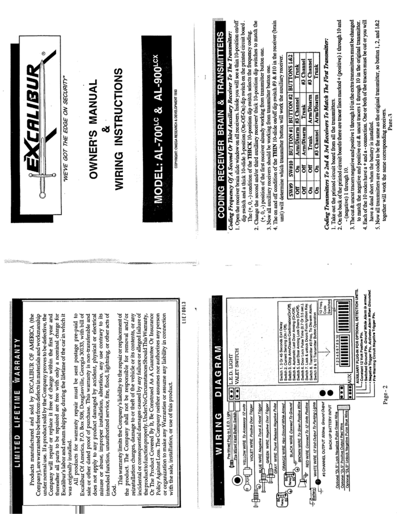
Switch#4-AutomaticIgnitionDoorlocking:Thisfeaturehasthesecuritysystemautomati-
callylock thedoors 1second afterthe ignitionswitch isturned on,and immediatelyunlock
themwhen the ignitionswitch is turnedoff. To have thisautomatic ignition lockingfeature
operate,setswitch#4tothe“up”position;toturnoffautomaticlockingandunlockingwhen
the ignition is turned on and off set switch #4 to the “down” position.
Automatic Ignition Doorlocking is factory-set “on” (switch #4 up)
Switch#5-CurrentSensing: Withthisfeatureturnedon,whentheAL-100-HisArmeditcan
then be Activated by its sensing a current draw from the vehicle's battery. To have the
system Activate if a current draw is sensed, set switch #5 “down”; to turn off Current
Sensing set switch #5 to the “up” position.
Current Sensing is factory-set “off” (switch #5 up)
Switch #6- 15 Second Entry Delay: When this feature is on, the system while wait 15
seconds before activating if a door is opened, but only if it was previously allowed to Last
DoorArmitself. PleaseconsulttheOperationGuideforafulldescriptionofhowthisfeature
affectsthe system’soperation. To turnonthe 15Second EntryDelay, set switch#6 tothe
“down” position, to turn off the 15 Second Entry Delay set switch #6 to the “up” position.
15 Second Entry Delay is factory-set “off” (switch #6 up)
Contents
Wiring Diagram...................................................................................................................... 16-17
Installation Considerations ......................................................................................................... 3-5
Mounting the Control Module, Status Light, Valet Switch & Optional Sensor Port
6-Pin Arm/Disarm Wiring Harness
Determining Connection Type ...................................................................................................... 6
Connection Type Wiring Diagrams ......................................................................................... 7-11
5-Pin Main Wiring Harness
Black Wire / Chassis Ground ..................................................................................................... 12
Red Wire / Constant Power ........................................................................................................ 12
Red, White & Orange Wires / Starter Interrupt ..................................................................... 13-14
Yellow Wire / Ignition Power .................................................................................................... 15
Gray Wire / Trunk Release Disarm Input .................................................................................. 15
8-Pin 6-Wire Secondary Wiring Harness
Green Wire / Negative Door Trigger ................................................................................ 15 & 18
Violet Wire / Positive Door Trigger...................................................................................... 18-19
Blue Wire / Negative Instant Trigger .................................................................................... 19-20
White Wire / Positive Flashing Parking Light Output .......................................................... 20-21
Pink Wire Horn Output ......................................................................................................... 22-23
Brown Wire / Positive Output for an Optional Electronic Siren .......................................... 23-24
Plug-In Power Doorlock Interface Port.................................................................................. 24-29
Programmable Features .......................................................................................................... 30-31
