manuals.online logo
Brands
  1. Home
  2. •
  3. Brands
  4. •
  5. Omega
  6. •
  7. Control Unit
  8. •
  9. Omega DB-PASS-23A User manual

Omega DB-PASS-23A User manual

Programming Jumper:
See FIG. A ,B or C for proper position
Red N/C
Green N/C
Blue N/C
Black(-) INPUT CONNECT TO CHASSIS GROUND OF VEHICLE
Pink N/C
Violet/White N/C
CONNECT TO (-) GROUND OUTPUT WHEN
BROWN (-) INPUT RUNNING WIRE OF REMOTE START SYSTEM
Pink/White N/C
Diagnostic plug (front view)
Located under the dash driver side:
below steering column
ORANGE (+)INPUT CONNECT TO ( 12 VOLTS CONSTANT+)
IMPORTANT: DO NOT CONNECT VIOLET
DATA OUTPUT WIRE OF INTERFACE MODULE
TO VEHICLE DATA WIRE (PIN 2) UNTIL EVERY
OTHER WIRE HAS BEEN CONNECTED & THE
HARNESS HAS BEEN PLUGGED INTO THE
DATA BUS INTERFACE (DL) MODULE.
DB-PASS-23A INSTALLATION
COMPATIBILITY CHART
1= INSTALL 1
2 = INSTALL 2
3= INSTALL 3
*DB-PASS-A will not disarm OEM alarm
Once DB-PASS- 23A harness is correctly connected:
Place programming jumper into PROGRAMMING POSITION
LED on DB-PASS-23A will blink 4 times after engine crank to indicate DB-PASS-23A is
programmed.
Turn ignition key to “OFF” position: then remove jumper from .
Place Jumper into OPERATING POSITION either:
INSTALL 1 PROGRAMMING
FIG:A
Plug DB-PASS-23A module into harness (Jumper must be in programming position)
Start vehicle with key.
PROGRAMMING POSITION
FIG.B: All PASSLOCK 2 or VATS
TECH NOTES:
*DB-PASS-23A IS NOT Compatible with GM Passlock 1
*DB-PASS-23A IS Only Compatible with VATS equipped with OBDII connector 1998+
*OBD1 EQUIPPED VEHICLES DO NOT HAVE A DATA WIRE TO CONNECT TO.
*Pontiac Sunfire, Chevrolet Cavalier, Malibu, Saturn equipped with content theft cannot be disarmed
during remote starting due to internal BCM function. DB-PASS-23A can be used but it is recommended to
add aftermarket keyless entry function and discontinue use of factory remote transmitters to avoid
triggering content theft alarm. Camaro & Firebird have similar content theft systems.
CONNECT TO VEHICLE VIOLET DATA WIRE
VIOLET(DATA OUTPUT) (PIN#2 OF OBDII DIAGNOSTIC CONNECTOR)
PROGRAMMING POSITION
OPERATING POSITION
Fig:A
Fig:B
A
A
B
B
(LED)
(LED)
OPERATION POSITION
For Cavalier & Sunfire
Without Factory Alarm
NOT USE
Fig:C
Fig:D
A
A
B
B
(LED)
(LED)
INSTALL 1
GM PLASSLOCK 2 (DATA)
GMBP INSTAL LATION COM PATIBILITY CHART
V EHIC L ES 2006 2005 2004 2003 2002 2001 2000 1999 1998
ALERO 11111
A URORA 2222
AVALANCHE 111
AZTEK 2* 2* 2* 2*
BONNEV ILLE 22222
BRAVADA 111
CA DILLA C CTS 22
CA DILLA C STS 2222222
CA DILLA C DEVILL E 2222222
CA DILLA C SLS 22
SIERRA CK 1500, 2500, 3500 11
ENV OY 111
RA INER 1
GRA ND A M 111111
GRA ND PRIX 3*
3* 3* 3* 3*
HUMMER H2 1
IMPA LA 1111
LESABRE 22222
MONTA NA 2* 2* 2* 2* 2* 2* 3*
MONTE CA RLO 1111
PARK AVENUE 2222222
RENDEZ-V OUS 2* 2* 2*
SUBURB A N 1111111
SUNFIRE 11111
CAVALIER 11111
SILHOUETTE 2* 2* 2* 2* 2* 3*
TRAILBLAZER 111
TRA NSPORT 2* 2* 2* 2* 3*
V ENTURE 2* 2* 2* 2* 2* 3*
YUKON 111* 1* 1* 1* 1*
DB-PASS23A
GM PASSLOCK II & PASSKEY III INTERFACE MODULE
DB-PASS-23A Installation Instructions
Fig:E
JUMPER POSITION
Unscrew cover of DB-PASS-23A unit.
Place jumper as seen below:
TO ECM SIDE
IGNITION
ORANGE - +12VOLTS CONSTANT
BLACK - GROUND
VIOLET - DATA OUTPUT
VIOLET -
NO CONNECTION
Pass-Key III
Module
PK3
N.C
GREY
CONNECTOR
BLACK
ORANGE
VIOLET
PINK
VIOLET - DATA TO ECM
RED - N/C
PINK - NC
VIOLET/TRACER - N/C
BROWN - CONNECT TO (-) IGNITION OUTPUT WIRE OF REMOTE START SYSTEM
GREEN - N/C
BLUE - N/C
PINK/TRACER - NC
ORANGE -+12 VOLTS CONTANT
BLACK -
CHASSIS GROUND
Programming LED
Programming Jumper
NOT USED
SEE FIG. E
PINK - IGNITION
ORANGE - ORANGE - +12VOLTS CONSTANT
BLACK - GROUND
BLUE FUEL ENABLE LINE
VIOLET - DATA OUTPUT
GREY - LED
Pass-KeyIII
Module
PK3
VIOLET - N/C
PINK - IGNITION IN
VIOLET/TRACER - N/C
GREEN - N/C
BLUE - FUEL ENABLE LINE
PINK/TRACER - IGNITION OUT
Programming LED
Programming Jumper
IMPORTANT: DO NOT CONNECT VIOLET
DATA OUTPUT WIRE OF INTERFACE MODULE
TO VEHICLE DATA WIRE (PIN 2) UNTIL EVERY
OTHER WIRE HAS BEEN CONNECTED & THE
HARNESS HAS BEEN PLUGGED INTO THE
DATA BUS INTERFACE (DL) MODULE.
When the DB-PASS-23A harness is correctly installed:
Place the programming jumper to the “PROGRAMMING” position. (See
urn to the “ON” position.
The LED will blink 4 times to confirm sucessful programming.
Turn key to the “OFF” position.
Remove the programming jumper and put it to position -
INSTALL 2 PROGRAMMING
FIG:A)
Place key in ignition and t
“OPERATING“ (See FIG:B)
Programming Position
Operating Position
Fig:A
Fig:B
A
A
B
B
(LED)
(LED)
INSTALL 2
GM PASSKEY3 (Pk3)
GREY
CONNECTOR
TO ECM SIDE
BROWN - CONNECT TO (-) GROUND OUTPUT
WHEN RUNNING WIRE OF REMOTE START SYSTEM
INSTALL 3
GM PASSKEY3 (Pk3)
BLACK - CHASSIS GROUND
RED - N/C
ORANGE -+12 VOLTS CONTANT
NO PROGRAMMING NECESSARY
NOTE: PLACE JUMPER AS SHOWN IN FIG:E BEFORE CONNECTING MODULE.
INSTALL 3:
TECH NOTES: *Vehicles with the ignition cylinder located on the dash: Yellow, Black & White wires can be
found coming from the ring of the cylinder - Trace these wires to the factory PK3 module located just abov
the gas pedal area.
GM PASSLOCK II & PASSKEY III INTERFACE MODULE
DB-PASS-23A
DBPASS-23-A
REMOTE START
MODULE
REMOTE START
MODULE
DB-PASS-23A Installation Instructions

Other Omega Control Unit manuals

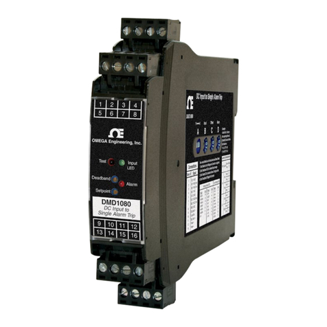
Omega DMD1080 User manual

Omega

Omega DMD1080 User manual

Omega DRC-4720 User manual

Omega

Omega DRC-4720 User manual

Omega OM-USB-2404-60 User manual

Omega

Omega OM-USB-2404-60 User manual

Omega OMB-AI-EXP32 User manual

Omega

Omega OMB-AI-EXP32 User manual

Omega OM-USB-TC-AI User manual

Omega

Omega OM-USB-TC-AI User manual

Omega FLSC790-P User manual

Omega

Omega FLSC790-P User manual

Omega OMB-DAQ-54 User manual

Omega

Omega OMB-DAQ-54 User manual

Omega OM-DAQ-USB-2401 User manual

Omega

Omega OM-DAQ-USB-2401 User manual

Omega DRG-SC-AC User manual

Omega

Omega DRG-SC-AC User manual

Popular Control Unit manuals by other brands

Proxim HZB-PROXMB92 user guide

Proxim

Proxim HZB-PROXMB92 user guide

Omron CJ1W-NC214 - datasheet

Omron

Omron CJ1W-NC214 - datasheet

Phoenix Mecano Dewert Okin ACCUCONTROL 4.5 installation instructions

Phoenix Mecano

Phoenix Mecano Dewert Okin ACCUCONTROL 4.5 installation instructions

ICP DAS USA SG-3784M user manual

ICP DAS USA

ICP DAS USA SG-3784M user manual

Murphy EMS-GC10 Operator's manual

Murphy

Murphy EMS-GC10 Operator's manual

Chicco Clip-On Electronic Module owner's manual

Chicco

Chicco Clip-On Electronic Module owner's manual

LS RESEARCH TiWi user guide

LS RESEARCH

LS RESEARCH TiWi user guide

BERMAD FP 430-UF Installation operation & maintenance

BERMAD

BERMAD FP 430-UF Installation operation & maintenance

HBM QuantumX MX840 operating manual

HBM

HBM QuantumX MX840 operating manual

BFT B EBA RS 485 LINK installation manual

BFT

BFT B EBA RS 485 LINK installation manual

GHL PLM-ADIN manual

GHL

GHL PLM-ADIN manual

Edwards GSA-CC1 Installation sheet

Edwards

Edwards GSA-CC1 Installation sheet

Seneca Z-4DI-2AI-2DO installation guide

Seneca

Seneca Z-4DI-2AI-2DO installation guide

Elk Products ELK-110 quick start guide

Elk Products

Elk Products ELK-110 quick start guide

Emerson Keystone EPI2 Installation, operation and maintenance manual

Emerson

Emerson Keystone EPI2 Installation, operation and maintenance manual

schmersal SRB 301LC/B operating instructions

schmersal

schmersal SRB 301LC/B operating instructions

iseg VHQ Series technical information

iseg

iseg VHQ Series technical information

Sony HDCU1000 installation manual

Sony

Sony HDCU1000 installation manual

manuals.online logo
manuals.online logoBrands
  • About & Mission
  • Contact us
  • Privacy Policy
  • Terms and Conditions

Copyright 2025 Manuals.Online. All Rights Reserved.