DESCRIPTION
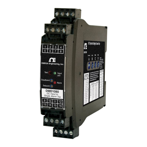
ThefieldconfigurableDRG-SC-ACis
a DIN rail mount, AC input signal
conditioner with 1800VDC isolation
betweeninput,outputandpower.The
field configurable input and output
offersflexible,wideranging capability
for scaling, converting or buffering
AC inputs ranging from 5mA to
100mAACor50mVto200VAC. The
DCoutputoftheDRG-SC-ACispro-
portional to the average of the of the
fully-rectified AC input signal, and is
calibratedforsinewavesbetween40-
400Hz.
Forcurrentinputsabove100mAAC,it
is recommended that an input shunt
resistorbeusedandtheDRG-SC-AC
be configured for the proper input
range. Forexample,a5AACcurrent
transformer output can use a 0.1Ω,
5Wshuntresistorandsettheinputof
the DRG-SC-AC for 0-500mVAC.
APPLICATION
TheDRG-SC-ACisusefulinapplica-
tionsrequiringanisolated,conditioned
DCoutputfromanACsignal. Typical
applicationsincludeenergymanage-
ment, load shedding, motor current/
load monitoring, locked rotor detec-
tion, isolation and data acquisition.
The output of the DRG-SC-AC can
driveadigitalmeterfordirect display
orcaninterfacewithalarmingorcon-
troldevicesincludingPLCsandcom-
puters.
DIAGNOSTICLED
The DRG-SC-AC is equipped with a
dualfunctionLEDsignalmonitor. The
green, front mounted LED indicates
bothDCpowerandinputsignalstatus.
Active DC power is indicated by an
illuminatedLED. If the inputsignalis
morethan110%ofthefull-scalerange,
theLEDwillquicklyflashat8Hz. Ifthis
continues to occur, you may wish to
change your full-scale input range
setting.
Note1: All DRG-Series modues are designed and tested to operate in ambient temperatures from 0
to 55
°
C, when
mounted on a horizontal DIN rail. When five or more modules are mounted on a vertical rail, circulating air or model
DRG-HS01 Heat Sink is recommended.
WARNING:
Donotattemptto
changeanyswitchsettingswithpower
applied. Severedamagewillresult!
DRG-SC-AC
AC Input, Field Configurable Isolator
Instruction Sheet M2389/0796
CONFIGURATION
Amajoradvantageofthe
DRG-SC-ACisitswiderangingcapa-
bilitiesandeaseofconfiguration. The
DRG-SC-AChas15inputrangeswitch
settings.
Trimpotentiometersallow50%input
zeroandspanadjustablitywithineach
of the 15 full-scale input ranges.
Forexample,the200Vswitchsetting
inTable1configurestheinputfora0
to200VACrange. Sincethespancan
becontractedby50%,thisenablesan
input span as narrow as 100VAC of
the range. This span can be posi-
tionedanywherewithinthe0-200VAC
range with a zero offset as large as
50% of the full scale range (e.g. 100
to 200VAC range).
Unlessotherwisespecified,the
factory presets the Model
DRG-SC-ACasfollows:
InputRange: 0-500mVAC
Output: 4-20mA
The DC power input accepts any DC
sourcebetween9and30V,typicallya
12V or 24VDC source is used
Refer to Tables 1 through 3 for the
proper switch settings. With power
disconnected, use the switches on
SW1toselecttheinputtype(voltageor
current),onSW2toselecttheHIorLO
inputranges,andonSW4toselectthe
desired input range. Using the
switches on SW3, select the desired
type of output.
CurrentOutput
Output:0-1mA,0-20mA,
4-20mA
SourceImpedance:>100KΩ
Compliance:
0-1mA;7.5V,max.(7.5KΩ,max.)
0-20mA;12V,max.(600Ω,max.)
4-20mA;12V,max.(600Ω,max.)
LED Indicator (green)
8Hzflash when input is 10%
abovefullscale range (FSR)
Accuracy(IncludingLinearity,Hyster-
esis)
+0.1%of span, typical
+0.5% of span, maximum
Stability
+0.025%/°Cofselectedinput
span,typical.
Response Time (10 to 90%)
250mSec.,typical.
Common Mode Rejection
DCto 60Hz: 120dB
Isolation
1800VDCbetweeninput,output
andpower.
EMC Compliance (CE Mark)
Emissions:EN50081-1
Immunity:EN50082-2
Safety:EN50178
Humidity(Non-Condensing)
Operating:15 to 95%(@ 45°C)
Soak: 90% for 24 hours (@ 65°C)
Temperature Range
Operating:0to55°C
(32to131°F)
Storage:-25to70°C
(-13to158°F)
Power
Consumption:1.5Wtypical,
2.5W max.
Range:9to30VDC
WireTerminations
Screw terminals for 12-22 AWG
AgencyApprovals
CSAcertifiedperstandardC22.2,
No.0-M91and142-M1987(FileNo.
LR42272).UL recognizedper stan-
dardUL508(FileNo.E99775).CE
ComplianceperEMCdirective89/
336/EECandLowVoltage73/23/EE.
Mounting
32mm and 35mm DIN Rail
PIN CONNECTIONS
11 DC Power (+)
12 DC Power (-)
21 DC Power (+)
22 DC Power (-)
41 ACSignalInput(Hot)
42ACSignalInput(Neu)
51 Output (+)
52Output (-)
SPECIFICATIONS
Inputs
VoltageInput
Ranges:100mVto200VAC
Impedance:>100KΩ
Overvoltage:300VAC
CurrentInput
Ranges:10mAto100mAAC
Impedance:20Ω,typical
Overcurrent:200mAAC
Overvoltage:60Vpeak
FrequencyRange:40to400Hz,
factorycalibratedat60Hz
CommonMode(InputtoGround):
1800VDC,max.
ZeroandSpanRange:
ZeroTurn-Up:50%offull
scalerange
SpanTurn-Down:50%offull
scalerange
Output
VoltageOutput
Output:0-5V,0-10V
SourceImpedance:<10Ω
Drive:10mA,max.
(1KΩ, min. @ 10V)
ServicingNorthAmerica:
Fax: (95) 203-359-7807
Fax: (514) 856-6886
Fax: (203) 359-7700
ServicingEurope:
Fax:(31)20 6434643
Fax:49(07056) 8540
Postbus 8034, 1180 LA Amstelveen, The Netherlands
Tel: (31)206418405
Toll FreeinBenelux: 060993344
Ostravska 767, 733 01 Karvina
Tel: 42(69)6311899
9, rue Denis Papin, 78190 Trappes
Tel:330130-621-400
Toll Free in France: 05-4-06342
Daimlerstrasse 26, D-75392 Deckenpfronn, Germany
Tel:49(07056) 3017
Toll Free in Germany: 0130 11 21 66
25SwanningtonRoad,
Broughton Astely, Leicestershire,
LE9 6TU, England
Tel: 44(1455)285520
Fax:44(1455) 283912
Fax:330130-699-120
Fax:42(69) 6311114
P.O. Box 7, Omega Drive
Irlam, Manchester,
M445EX,England
Tel: 44 (161) 777-6611
Fax:44(161) 777-6622
Toll Freein England:0800-488-488
976 Bergar
Laval (Quebec) H7L 5A1
Telephone: (514) 856-6928
Forimmediate technicalseviceorapplicationassistance:
Sales Service: 1-800-826-6342 / 1-800-TC-OMEGASM
CustomerService:1-800-622-2378 /1-800-622-BESTSM
Engineering Service: 1-800-872-9436 / 1-800-USA-WHENSM
TELEX:996404 EASYLINK:62968934 CABLE: OMEGA
Tel: (95) 800-TC-OMEGASM
En Espanol: (203) 359-1660 ext. 2203
One Omega Drive, Box 4047
Stamford,CT06907-0047
Telephone: (203) 359-1660
USA:
ISO 9001 Certified
Canada:
USAand Canada:
Mexicoand
LatinAmerica:
Benelux:
CzechRepublic:
France:
Germany/Austria:
UnitedKingdom:
ISO 9002 Certified
Internet e-mail
OMEGAnetSM On-LineService
http://www.omega.com
WARRANTY/DISCLAIMER
RETURNREQUEST/ INQUIRIES
Directallwarrantyandrepairrequests/inquiriestotheOMEGACustomerServiceDepartment. BEFORERETURNINGANYPRODUCT(S)TOOMEGA,PURCHASER
MUSTOBTAINANAUTHORIZEDRETURN(AR)NUMBERFROMOMEGA'SCUSTOMERSERVICEDEPARTMENT(INORDERTOAVOIDPROCESSING
DELAYS).TheassignedARnumbershouldthenbemarkedontheoutsideofthereturnpackageandonanycorrespondence.
Thepurchaserisresponsibleforshippingcharges,freight,insuranceandproperpackagingtopreventbreakageintransit.
FORWARRANTYRETURNS,pleasehavethefollowinginformation
availableBEFOREcontactingOMEGA:
1. P.O.numberunderwhichtheproductwasPURCHASED,
2. Modelandserialnumberoftheproductunderwarranty,and
3. Repairinstructionsand/orspecificproblemsrelativetotheproduct
OMEGAENGINEERING,INC.warrantsthis unittobefreeof manufacturingdefectsforthelifeoftheproduct.
Iftheunit shouldmalfunction,itmust bereturnedto thefactoryforevaluation. OMEGA'sCustomerServiceDepartment willissueanAuthorized Return(AR)number
immediatelyuponphoneor writtenrequest.Uponexamination by OMEGA,iftheunit is foundtobedefective itwillberepairedor replacedatnocharge. OMEGA's
WARRANTYdoes notapplytodefectsresultingfromanyactionofthepurchaser, includingbutnotlimitedtomishandling,improperinterfacing,operationoutsideofdesign
limits,improperrepair,orunauthorizedmodification.ThisWARRANTYisVOIDiftheunitshowsevidenceofhavingbeentamperedwithorshowsevidenceofbeingdamaged
asaresultofexcessivecorrosion;or current,heat,moistureorvibration;improperspecification; misapplication;misuseorotheroperating conditionsoutsideofOMEGA's
control.Componentswhichwearare notwarranted,includingbutnot limitedtocontactpoints,fuses, andtriacs.
OMEGAispleasedtooffer suggestionsonthe useof itsvariousproducts. However,OMEGAneitherassumesresponsibility foranyomissions orerrorsnor assumesliability forany
damagesthat resultfromtheuseof itsproducts inaccordance withinformationprovidedbyOMEGA, eitherverbal orwritten. OMEGAwarrantsonlythat theparts manufacturedby
itwill beas specifiedand freeofdefects.OMEGAMAKESNOOTHERWARRANTIESORREPRESENTATIONSOFANYKINDWHATSOEVER,EXPRESSEDOR IMPLIED,
EXCEPTTHATOF TITLE, ANDALL IMPLIEDWARRANTIESINCLUDINGANYWARRANTY OFMERCHANTABILITY ANDFITNESS FORA PARTICULARPURPOSE
ARE HEREBYDISCLAIMED. LIMITATION OFLIABILITY: Theremedies ofpurchaser setforth hereinare exclusive andthe total liabilityof OMEGAwithrespecttothis order,
whetherbasedoncontract,warranty, negligence,indemnification, strictliability orotherwise,shallnotexceedthepurchase priceofthecomponent uponwhich liabilityisbased.Inno
eventshall OMEGAbeliableforconsequential,incidentalorspecialdamages.
CONDITIONS:Equipment soldbyOMEGAisnotintendedtobeused,norshallitbeused:(1)asa"BasicComponent"under10 CFR21(NRC),usedinorwithanynuclear
installationoractivity;or(2)inmedicalapplications orusedon humans.Shouldany Product(s)beusedinorwithanynuclear installationoractivity,medicalapplication,
usedon humans,ormisusedinanyway,OMEGAassumesnoresponsibilityassetforthinourbasic WARRANTY/DISCLAIMER language, andadditionally,purchaserwill
indemnifyOMEGAandholdOMEGA harmlessfromany liabilityordamagewhatsoeverarisingoutofthe useofthe Product(s)insuchamanner.
FORNON-WARRANTYREPAIRS,consultOMEGAforcurrentrepair
charges.HavethefollowinginformationavailableBEFOREcontactingOMEGA:
1. P.O.numbertocovertheCOSToftherepair,
2. Modelandserialnumberofproduct,and
3. Repairinstructionsand/orspecificproblemsrelativetotheproduct.
OMEGA'spolicyistomakerunningchanges,notmodelchanges,wheneveranimprovementispossible.Thisaffordsourcustomersthelatestintechnologyand
engineering.
OMEGAisaregisteredtrademarkofOMEGAENGINEERING,INC.
ãCopyright1996OMEGAENGINEERING, INC.Allrightsreserved.Thisdocumentationmaynot becopied,photocopied,reproduced,translated,orreducedtoany
electronicmediumormachine-readableform,inwholeorinpart,withoutpriorwrittenconsent ofOMEGAENGINEERING, INC.
It is the policy of OMEGA to comply with all worldwide safety and EMC/EMI regulations that apply. OMEGA is constantly pursuing certification of its products to the European
New Approach Directives. OMEGA will add the CE mark to every appropriate device upon certification.
The information contained in this document is believed to be correct but OMEGA Engineering, Inc. accepts no liability for any errors it contains, and reserves the right to alter
specifications without notice.
WARNING: These product are not designed for use in, and should not be used for, patient connected applications.
721-0610-00B 11/96
