Omega 44700 Instructions for use
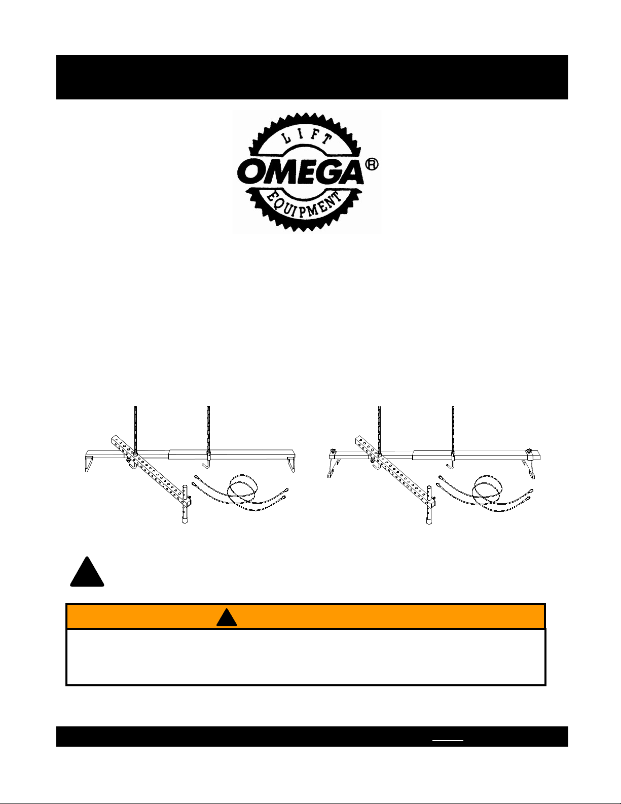
Engine Transverse Bar
w/Support Arm
Printed in China
44700-M0 12/07
Operating Instructions & Parts Manual
Read this manual and follow all the Safety Rules and Operating Instructions before using this product.
SFA Companies
http://www.omegalift.com
Model
44700
44100
Capacity
700 lb.
1000 lb.
Model 44700 Model 44100
This is the safety alert symbol. It is used to alert you to potential personal injury hazards.
Obey all safety messages that follow this symbol to avoid possible injury or death.
!
! ADVERTENCIA
• Leer, comprender, y seguir las instrucciónes antes de utilizar el aparato.
• El manual de instrucciónes y la información de seguridad deben estar comunicado en lengua del operador
antes del uso.
• No seguir estas indicaciónes puede causar daños personales o materiales.
2
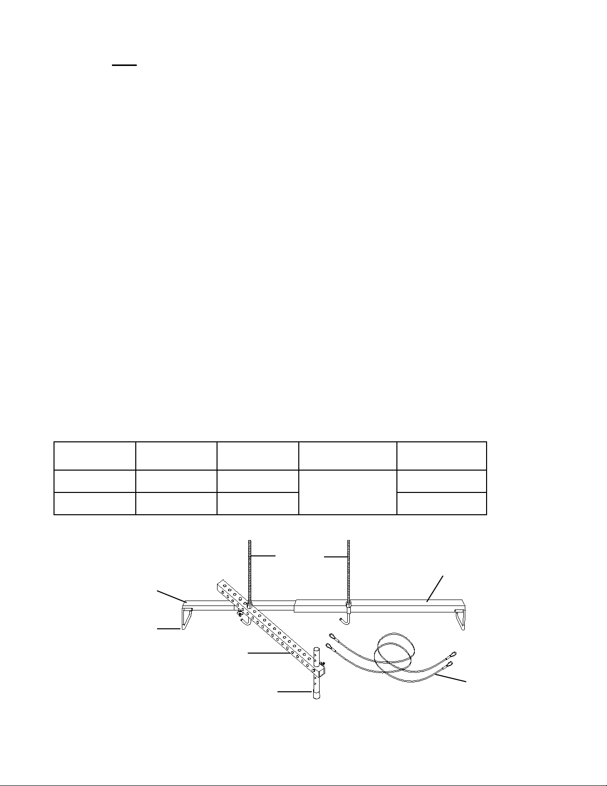
SPECIFICATIONS
Figure 1 - Engine Transverse Bar Components (model 44700 shown)
SAFETY and GENERAL INFORMATION
Save these instructions. For your safety, read, understand and follow the information contained within. The owner
and operator shall have an understanding of this product and safe operating procedures before attempting to use
this product. Instructions and Safety information shall be conveyed in the operator's native language before use of
this product is authorized. Make certain that the operator thoroughly understands the inherent dangers associated
with the use and misuse of the product. If any doubt exists as to the safe and proper use of this product as outlined
in this factory authorized manual, remove from service.
Inspect before each use. Do not use if there are broken, bent, cracked or otherwise damaged parts (including
labels). Owners and operators of this equipment shall be aware that the use of this equipment may require special
training and knowledge. It is recommended that an annual inspection be done by qualified personnel and that any
missing or damaged decals, warning / safety labels or signs be replaced with factory authorized replacements only.
Any engine transverse bar that appears to be damaged in any way, is worn or operates abnormally shall be removed
from service immediately.
PRODUCT DESCRIPTION
Omega Engine Transverse Bar is designed to safely support engine up to 700 lb. It assists the removal of transaxle
easily by supporting engine of front wheel drive vehicle. Heavy duty steel frame helps prevent distortion and twisting.
Compliance with factory standards ensures safety, strength and stability.
Cable
Boom
Adjustable Leg
Threaded
Hooks
Boom Leg
Boom Extension
Support Arm
BEFORE USE
1. Verify that the product and the application are compatible, if in doubt call Omega Tech. Service (888) 332-6419.
2. Before using this product, read the operator's manual completely and familiarize yourself thoroughly with the
product, its components and recognize the potential hazards associated with its use.
3. Inspect before each use. Do not use if bent, broken or cracked components are noted.
4. Ensure that all parts move freely.
Model Capacity Boom Length
Expand Hook Thread Length Shipping Weight
44700 700-lb. 38” ~ 61”
12.5”
27.5 lb.
44100 1000-lb. 61" 31.0. lb.

3
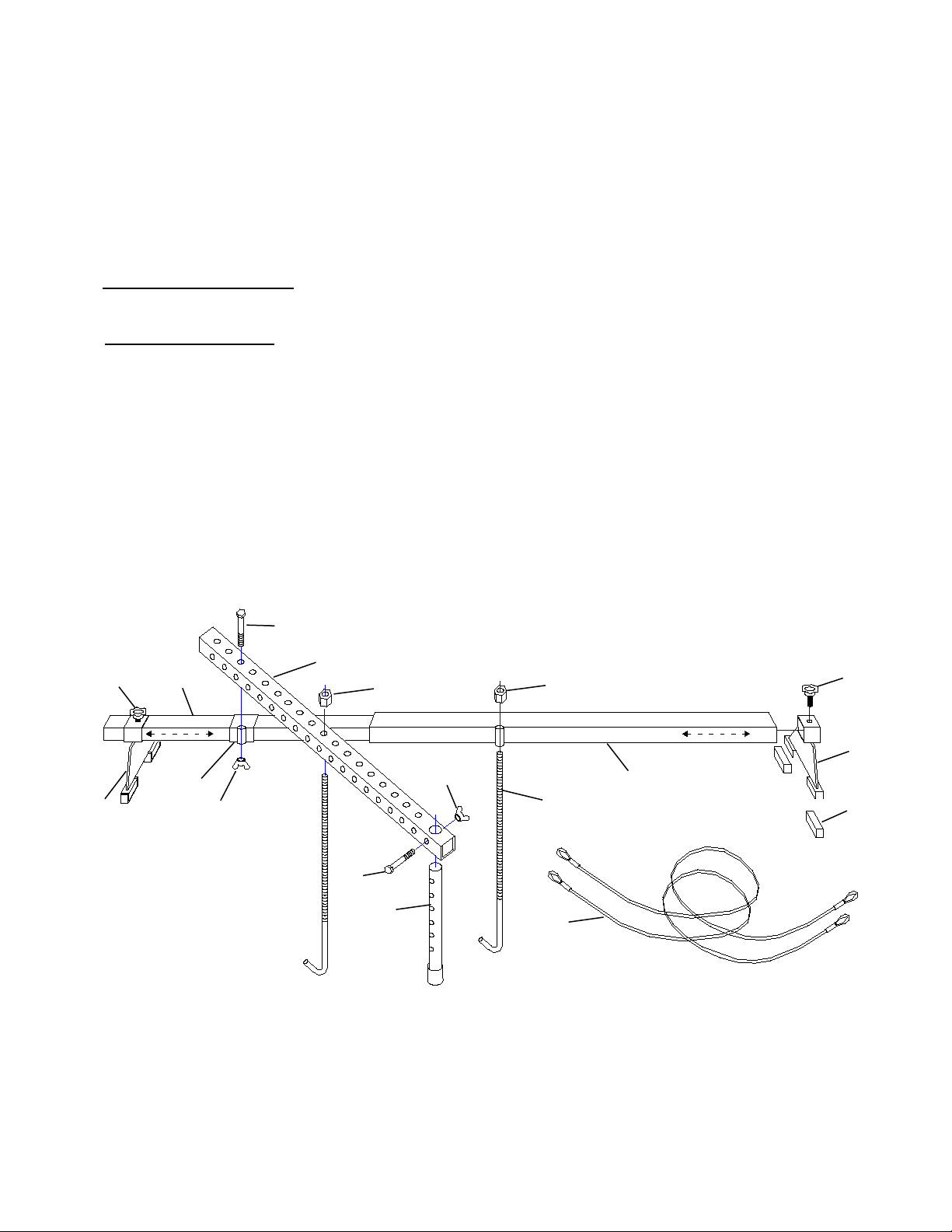
ASSEMBLY INSTRUCTION FOR MODEL 44700
(refer to Figure 2)
1. Insert the wide leg (#13) into tube welded at the end of boom (#1) and the narrow leg (#14) to boom extension
(#2).
2. Slide transfer adapter (#11) over the end of boom extension (#2) with tube toward you.
3. Insert the boom extension (#2) into boom (#1).
NOTE: The Engine Transverse Bar may be used with or without support arm, depending on the load being
supported.
4. To use without support arm: Secure both threaded hooks (#3) to the tube welded on boom and transfer adapter
with barrel hex. nut (#7). Thread the hex. nut (#7) all the way down towards the hook portion to hold it out of the
way until needed.
5. To use with support arm:
(a) Insert the adjustable leg (#6) to support arm (#10), then hand tight with M8x65 bolt and wing nut (#9 & 8). Do
not fully tighten wing nut as height adjustment may be necessary once the Engine Transverse Bar is placed
over the engine compartment of the vehicle.
(b) After determining the length of support arm needed, Connect the support arm (#10) to transfer adapter (#11)
on the boom extension with M12x120 bolt and wing nut (#5 & 4). Again, do not fully tighten as some length
adjustment may be required.
(c) Before placing the Engine Transverse Bar over the engine compartment, install the two threaded hooks (#3)
provided. Insert one hook to the tube welded on boom (#1) and secure with barrel hex. nut (#7). Thread the
hex. nut (#7) all the way down towards the hook portion to hold it out of the way until needed. Then, locate the
best position on the support arm for the second hook and install in the same manner.
6. Now the Engine Transverse Bar is ready to use.
Figure 2 - Model 44700 Assembly & Parts Illustration
4
ASSEMBLY INSTRUCTION FOR MODEL 44100
(refer to Figure 3)
1. Slide the bigger leg (#13) into boom (#1) and smaller leg (#14) to boom extension (#2). Secure the legs by tighten
the knob screws (#16). The rubber blocks (#17) is attached to the bottom of legs.
2. Slide transfer adapter (#11) over the boom extension (#2) with tube toward you.
3. Insert the boom extension (#2) into boom (#1).
NOTE: The Engine Transverse Bar may be used with or without support arm, depending on the load being
supported.
4. To use without support arm: Secure both threaded hooks (#3) to the tube welded on boom and transfer adapter
with barrel hex. nut (#7). Thread the nut all the way down towards the hook portion to hold it out of the way until
needed.
5. To use with support arm:
(a) Insert the adjustable leg (#6) to support arm (#10), then hand tight with M8x65 bolt and wing nut (#9 & 8). Do
not fully tighten wing nut as height adjustment may be necessary once the Engine Transverse Bar is placed
over the engine compartment of the vehicle.
(b) After determining the length of support arm needed, Connect the support arm (#10) to transfer adapter (#11)
on the boom extension with M12x120 bolt and wing nut (#5 & 4). Again, do not fully tighten as some length
adjustment may be required.
(c) Before placing the Engine Transverse Bar over the engine compartment, install the two threaded hooks (#3)
provided. Insert one hook to the tube welded on boom (#1) and secure with barrel hex. nut (#7). Thread the
nut all the way down towards the hook portion to hold it out of the way until needed. Then, locate the best
position on the support arm for the second hook and install in the same manner.
6. Now the Engine Transverse Bar is ready to use.
Figure 3 - Model 44100 Assembly & Parts Illustration
1
2
3
4
5
6
7
7
8
9
10
11
12
16
13
17
14
16
MAINTENANCE
Periodically inspect the Engine Transverse Bar. Ensure
all parts move freely. To help prevent rust, wipe clean
and/or blow dry after each use. If rust appears, sand
affected area and cover with suitable utility paint. Store
the Engine Transverse Bar in a clean, dry area.
REPLACEMENT PARTS
(Refer to Figure 2 & 3)
Not all components of the Engine Transverse Bar are
replacement items, but are illustrated as a convenient
reference of location and position in the assembly
sequence. When ordering parts, give part number
and description. Call or write for current pricing: SFA
Companies 10939 N. Pomona Ave. Kansas City, MO
64153, U.S.A. E-Mail: [email protected]
Tel: (888)332-6419 Fax: (816)891-6599
Omega Website: http://www.omegalift.com
OPERATION
1. Determine the location of the two engine support bolts
on your vehicle. Then place the Engine transverse
bar directly over these two bolts.
2. Adjust the boom extension (#2) to ensure that both
legs (#13 & 14) are sitting inside the fender of the
engine compartment.
If the inside fender lips are more than 61" apart
apart, the Engine Transverse Bar must not be
used. Do not exceed the designated marking (61").
Over-extending could cause the Engine Support Bar
to collapse, resulting in personal injury or property
damage.
3. Adjust to ensure the support arm (#10) is in correct
position. The rubber tip of the adjustable leg (#6)
should be on a flat, reinforced surface capable of
supporting the weight of engine. Tighten both wing
nuts (#4 & 8) to secure the adjustable leg (#6) and
support arm (#10).
4. Lower the threaded hooks (#3) to appropriate position.
Ensure that the hooks are directly over the engine
support bolts or brackets; therefore the engine does
not swing when vehicle is disassembled.
5. Attach the looped ends of the two 1/8" braided
steel cables (#12) to the engine support bolts on
the engine and loop middle of braided cables over
hooks. If the engine being supported is equipped with
engine lift brackets, hook the hooks (#3) directly into
engine lift brackets for extra protection.
Note: Use only fasteners rated Grade 5 or higher as
engine support bolts.
6. Tighten the barrel hex. nuts (#7) on both hooks
until cables are snug or hex. nuts are tight against
support bar.
7. Double check that engine is properly supported
before disassemble the vehicle.
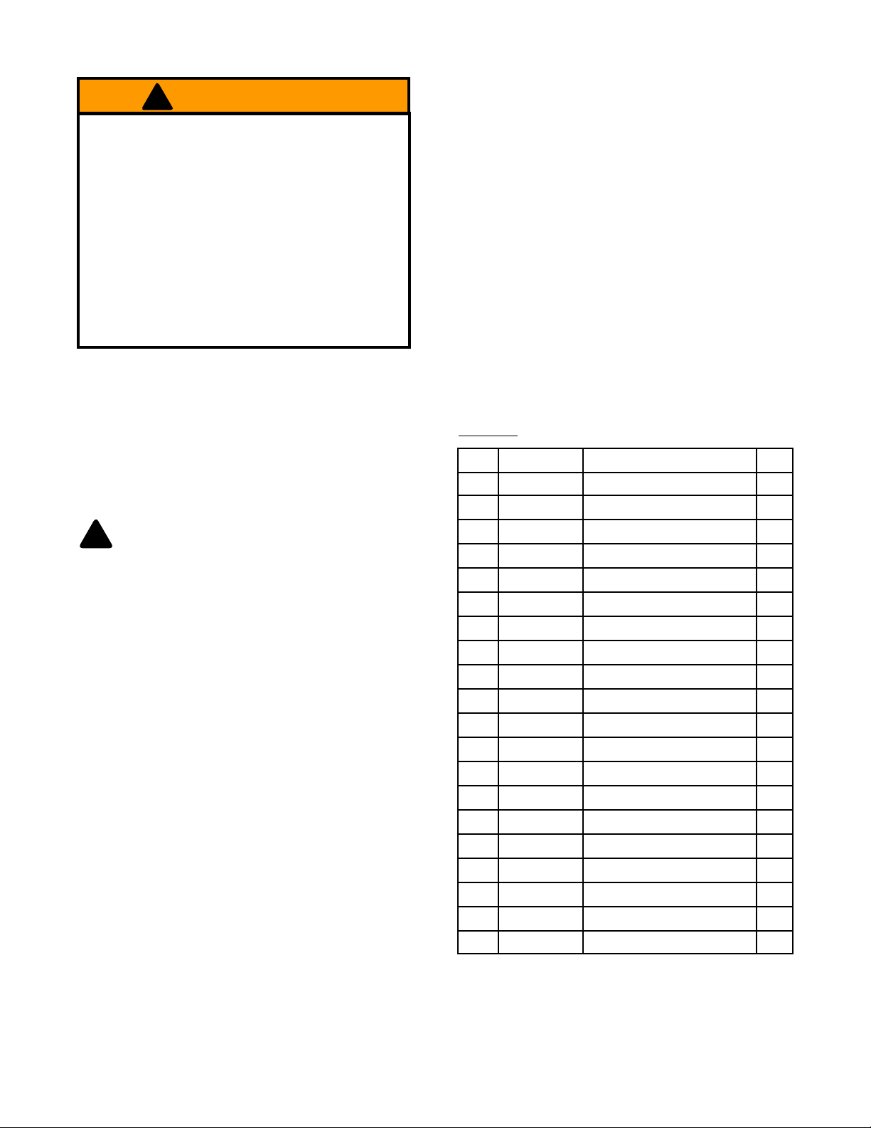
Item Part No. Description Qty
1 - Boom 1
2 - Boom Extension 1
3 * Threaded Hook 2
4 * Wing Nut, M12 1
5 * Hex. Bolt M12x120 1
6 44700-6 Adjustable Leg 1
7 * Barrel Hex. Nut 2
8 * Wing Nut, M8 1
9 * Hex. Bolt M8x65 1
10 - Support Arm 1
11 - Transfer Adapter 1
12 44700-12 Braided Steel Cable, 1/8" 2
13 - Leg, Boom 1
14 - Leg, Boom Extension 1
(*) 44700-15 Hardware Kit -
16 - Knob Screw 1
17 - Rubber Block (44100) -
- 44700-M0 Manual -
- 44700-L0 Label for 44700 -
- 44100-L0 Label for 44100 -
Parts List
(*) Hardware Kit includes item# 3, 4, 5, 7, 8 & 9
5
!
• Study, understand, and follow all instructions
provided before use.
• Do not exceed rated capacity.
• Do not exceed maximum width.
• Never crawl under the suspended load for any
reason.
• Ensure that the engine is supported securely
before repairing.
• Do not use this device for any purpose other than
that for which it is intended.
• No alterations shall be made to this product.
• Failure to heed these markings may result in
personal injury and/or property damage.
! WARNING

ONE YEAR LIMITED WARRANTY
For a period of one (1) year from date of purchase, SFA Companies will repair or replace, at its option,
without charge, any of its products which fails due to a defect in material or workmanship under normal usage. This
limited warranty is a consumer's exclusive remedy.
Performance of any obligation under this warranty may be obtained by returning the warranted product, freight
prepaid, to SFA Companies Warranty Service Department, 10939 N. Pomona Ave., Kansas City, MO 64153.
Except where such limitations and exclusions are specifically prohibited by applicable law, (1) THE
CONSUMER'S SOLE AND EXCLUSIVE REMEDY SHALL BE THE REPAIR OR REPLACEMENT OF DEFECTIVE
PRODUCTS AS DESCRIBED ABOVE. (2) SFA Companies SHALL NOT BE LIABLE FOR ANY CONSEQUENTIAL
OR INCIDENTAL DAMAGE OR LOSS WHATSOEVER. (3) ANY IMPLIED WARRANTIES, INCLUDING WITHOUT
LIMITATION THE IMPLIED WARRANTIES OF MERCHANTABILITY AND FITNESS FOR A PARTICULAR
PURPOSE, SHALL BE LIMITED TO ONE YEAR, OTHERWISE THE REPAIR, REPLACEMENT OR REFUND AS
PROVIDED UNDER THIS EXPRESS LIMITED WARRANTY IS THE EXCLUSIVE REMEDY OF THE CONSUMER,
AND IS PROVIDED IN LIEU OF ALL OTHER WARRANTIES, EXPRESS OR IMPLIED. (4) ANY MODIFICATION,
ALTERATION, ABUSE, UNAUTHORIZED SERVICE OR ORNAMENTAL DESIGN VOIDS THIS WARRANTY AND
IS NOT COVERED BY THIS WARRANTY.
Some states do not allow limitations on how long an implied warranty lasts, so the above limitation may not
apply to you. Some states do not allow the exclusion or limitation of incidental or consequential damages, so the
above limitation or exclusion may not apply to you. This warranty gives you specific legal rights, and you may also
have other rights, which vary from state to state.
SFA Companies
10939 N. Pomona Ave. Kansas City, MO 64153
888-332-6419
6
This manual suits for next models
1
Table of contents
Other Omega Tools manuals


