This guide may change without notice. See www.OmegaEVO.com for latest version.
Ce guide peut faire l’objet de changement sans préavis. Voir www.OmegaEVO.com pour la dernière version.
REMOTE STARTER FUNCTIONNALITY | FONCTIONNALITÉ DU DÉMARREUR À DISTANCE
Remote start the
vehicle.
Démarrez à
distance.
Enter the vehicle
with the Smart-Key.
Entrez dans le
véhicule avec la clé
intelligente (Smart-
Key) sur vous
The vehicle can now
be put in to gear
and driven.
Vous êtes
maintenant prêt à
embrayer et prendre
la route.
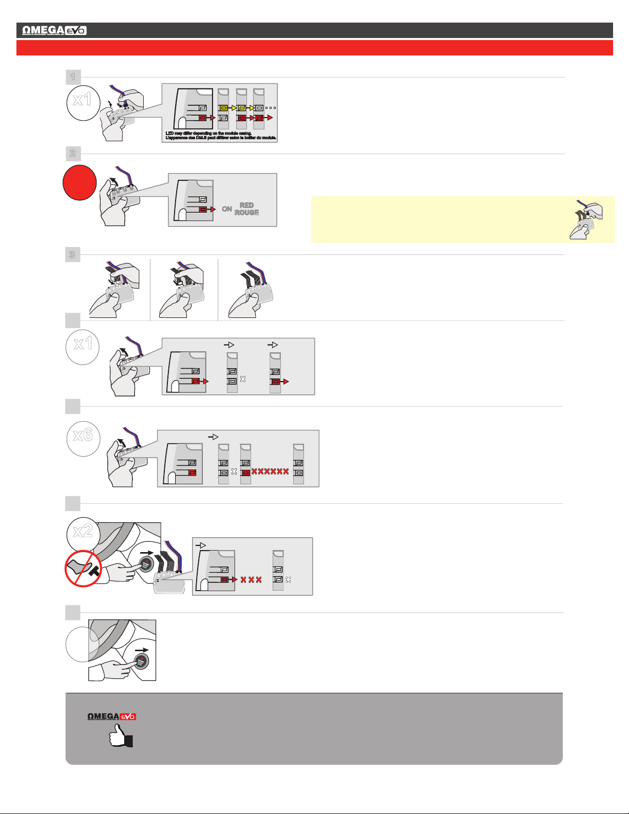
START
press the Push-to-
Start button twice to
turn ON the ignition.
appuyez 2 fois sur
le bouton démarrage
(Push-to-Start) pour
allumer l'ignition.
ON
x2
REMOTE STARTER FUNCTIONNALITY | FONCTIONNALITÉ DU DÉMARREUR À DISTANCE
Remote start the
vehicle.
Démarrez à
distance.
Enter the vehicle
with the Smart-Key.
Entrez dans le
véhicule avec la clé
intelligente (Smart-
Key) sur vous
The vehicle can now
be put in to gear
and driven.
Vous êtes
maintenant prêt à
embrayer et prendre
la route.
START
press the Push-to-
Start button twice to
turn ON the ignition.
appuyez 2 fois sur
le bouton démarrage
(Push-to-Start) pour
allumer l'ignition.
ON
x2
REMOTE STARTER FUNCTIONNALITY | FONCTIONNALITÉ DU DÉMARREUR À DISTANCE
Page 5 / 5
Notice: Updated Firmware and Installation Guides
Updated fi rmware and installation guides are posted on our web site on a regular
basis. We recommend that you update this module to the latest firmware and
download the latest installation guide(s) prior to the installation of this product.
Notice: Mise à jour microprogramme et Guides d’installations
Des mises à jour du Firmware (microprogramme) et des guides d’installation
sont mis en ligne régulièrement. Vérifiez que vous avez bien la dernière version
logiciel et le dernier guide d’installation avant l’installation de ce produit.
TECH SUPPORT
ADDENDUM GUIDE WEB UPDATE | MISE À JOUR INTERNET
Service No : 000 102 04 2536
Date: xx-xx
INTERFACE MODULE
Made in Canada
PATENTS PENDING US: 2007-228827-A1
www.fortinbypass.com
HARDWARE VERSION
FIRMWARE VERSION
Module label | Étiquette sur le module
OM-EVO-KEY
www.OmegaEVO.com
TEL.: 770-942-9876
1-800-554-4053
WARNING
The information on this sheet is provided on an (as is) basis with no representation or warranty of accuracy whatsoever. It is the
sole responsibility of the installer to check and verify any circuit before connecting to it. Only a computer safe logic probe or
digital multimeter should be used. OMEGA RESEARCH & DEVELOPMENT TECHNOLOGIES, INC. assumes absolutely no
liability or responsibility whatsoever pertaining to the accuracy or currency of the information supplied. The installation in every
case is the sole responsibility of the installer performing the work and OMEGA RESEARCH & DEVELOPMENT TECHNOLO-
GIES, INC. assumes no liability or responsibility whatsoever resulting from any type of installation, whether performed properly,
improperly or any other way. Neither the manufacturer or distributor of this module is responsible of damages of any kind indirec-
tly or directly caused by this module, except for the replacement of this module in case of manufacturing defects. This module
must be installed by qualified technician. The information supplied is a guide only. This instruction guide may change without
notice. Visit www.OmegaEVO.com to get the latest version.
MISE EN GARDE
L’information de ce guide est fournie sur la base de représentation (telle quelle) sans aucune garantie de précision et d’exactitude.
Il est de la seule responsabilité de l’installateur de vérifier tous les fils et circuits avant d’effectuer les connexions. Seuls une sonde
logique ou un multimètre digital doivent être utilisés. OMEGA RESEARCH & DEVELOPMENT TECHNOLOGIES, INC.
n’assume aucune responsabilité de l’exactitude de l’information fournie. L’installation (dans chaque cas) est la responsabilité de
l’installateur effectuant le travail. OMEGA RESEARCH & DEVELOPMENT TECHNOLOGIES, INC. n’assume aucune respon-
sabilité suite à l’installation, que celle-ci soit bonne, mauvaise ou de n’importe autre type. Ni le manufacturier, ni le distributeur
ne se considèrent responsables des dommages causés ou ayant pu être causés, indirectement ou directement, par ce module,
excepté le remplacement de ce module en cas de défectuosité de fabrication. Ce module doit être installé par un technicien
qualifié. L’information fournie dans ce guide est une suggestion. Ce guide d’instruction peut faire l’objet de changement sans
préavis. Consultez le www.OmegaEVO.com pour voir la plus récente version.
Copyright © 2006-2015, OMEGA RESEARCH & DEVELOPMENT TECHNOLOGIES, INC.ALL RIGHTS RESERVED PATENT PENDING
KEY
Page 5 / 5