Page 3 / 4
This guide may change without notice. See www.OmegaEVO.com for latest version.
Ce guide peut faire l’objet de changement sans préavis. Voir www.OmegaEVO.com pour la dernière version.
INSTALLATION PROCEDURE | PROCÉDURE D’INSTALLATION
1Déterminez si le démarreur
à distance ou système
d'alarme est compatible en
Data-Link 2-voies.
Determine if the remote-
starter or alarm system
supports 2-way Data-Link.
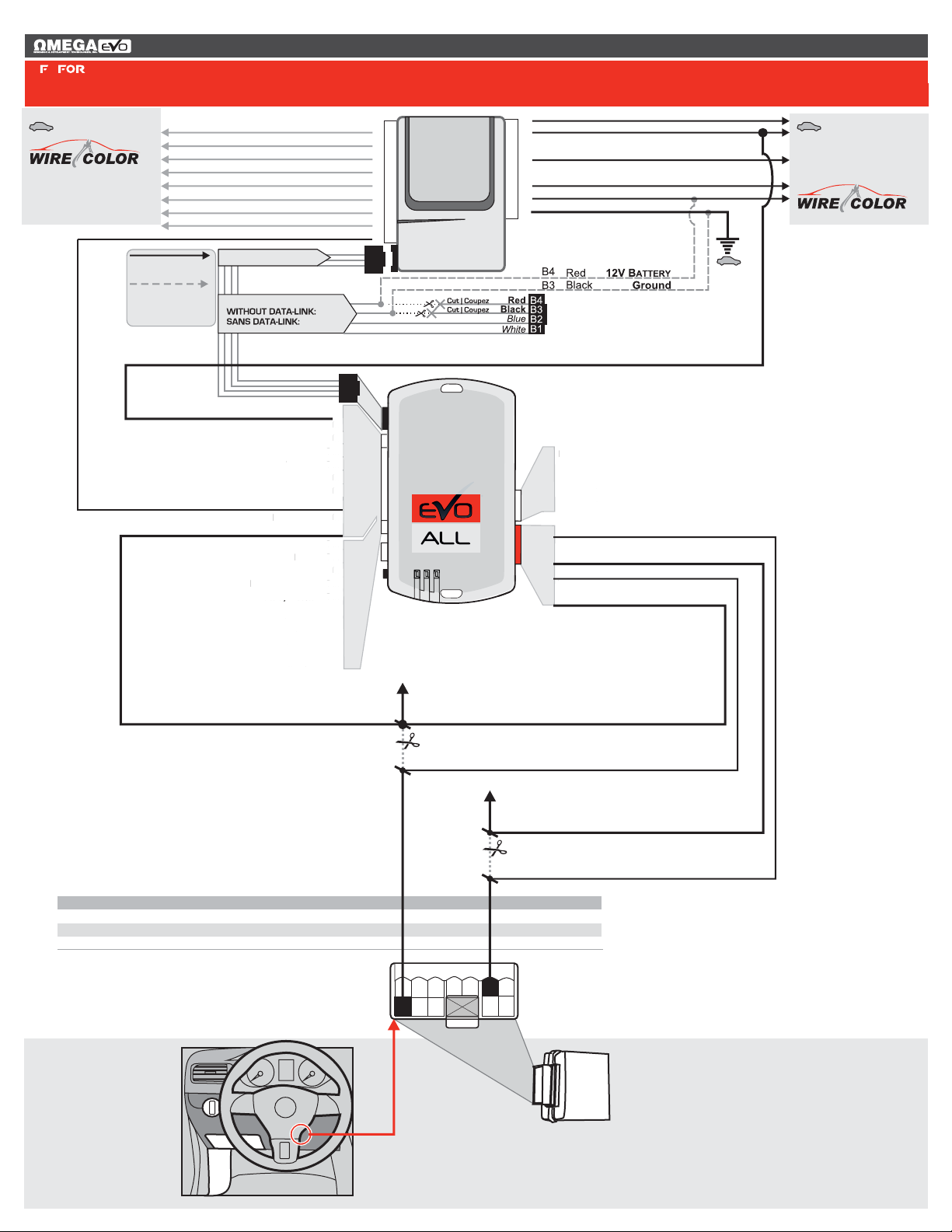
2Faire les branchements:Make the connections:
Remote
Starter/Alarm
Démarreur à
distance/alarme
4 Pin
WITH DATA-LINK
AVEC DATA-LlNK
In order to use this type of connection the
remote-starter or alarm-system must be
compatible with the
. Consult the installation guide or
visit www.fortinbypass.com/datalink/ for more
information.
Fortin Data-link
protocol
Red | Rouge +12V
Black | Noir Ground
20 Pin Conn. 4 Pin
For all other remote-starters or
alarm-systems perform the
following connections.
WITH OUT DATA-LINK
SANS DATA-LlNK
Cut off one plug of the 4 Pin
Data-Link connector
Connect the Red wire to +12V
Connect the Black wire to
Ground
1
2
3
Coupez l'extrémité du connecteur
4 pins Data-Link
Connectez le fil rouge au 12V
Connectez le fil noir à la masse
du véhicule.
1
2
3
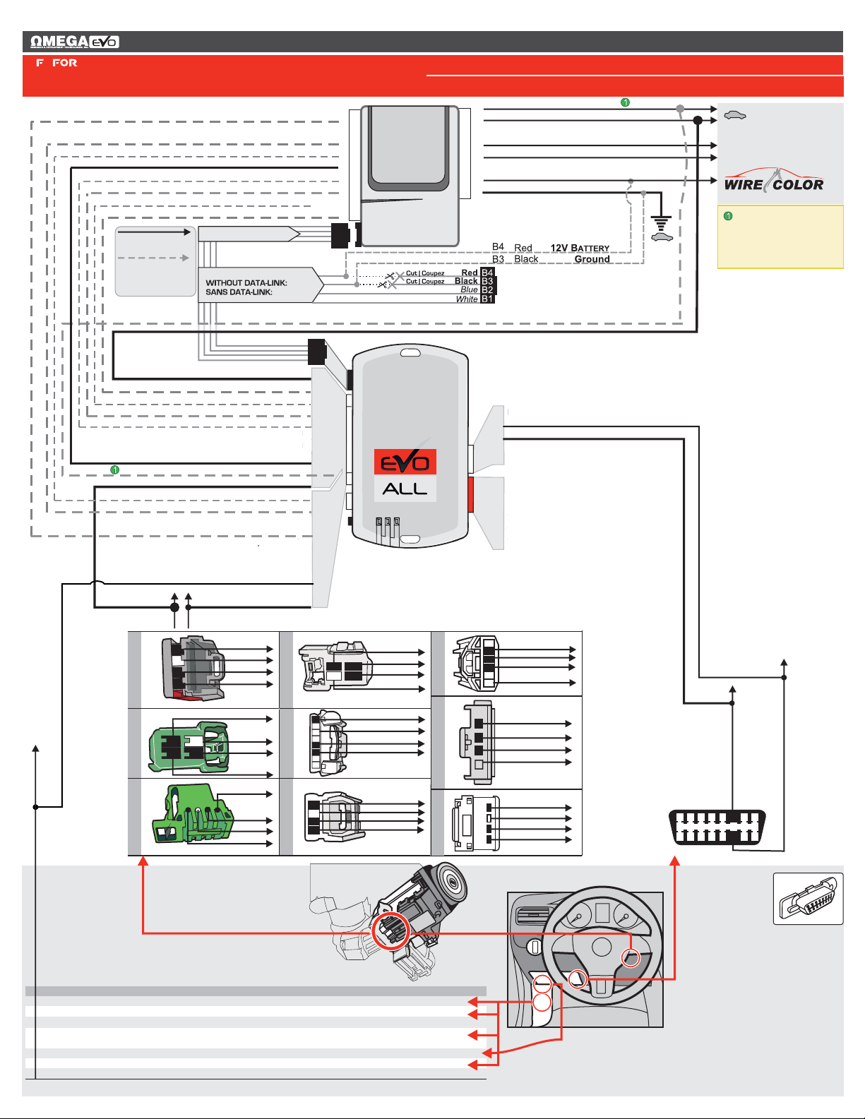
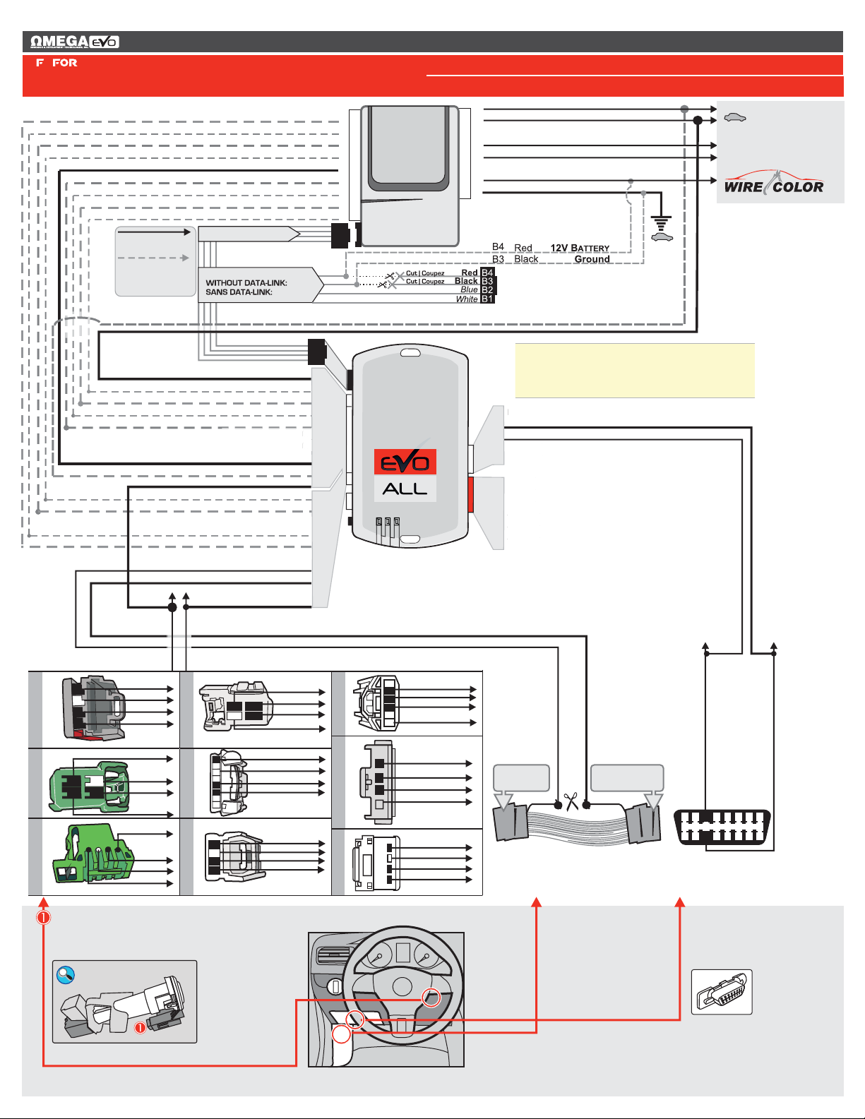
3PROCÉDURE DE
PROGRAMMATION
PROGRAMMING
PROCEDURE
Determine the programming procedure
required for the vehicle in the VEHICLE
FIT GUIDE.
Déterminez le type de programmation selon
votre véhicule dans le GUIDE DES
VÉHICULES.
VEHICLE MAKE MODEL YEAR
CONNECTION # PROGRAM: #
Connection number
Numéro de connection
Programming number
Numéro de programmation
Vehicle(s) associated with the procedure
Véhicule(s) associé(s) à la configuration
Remote
Starter/Alarm
Démarreur à
distance/alarme
20 Pins Connecteur (Blanc ):
Effectuez les branchements associés au
véhicule dans le GUIDE DES VÉHICULES.
20 Pin Connector (White):
Make the connections associated with
the vehicle from the VEHICLE FIT
GUIDE.
5 Pins Connecteur CAN (Blanc):
Effectuez les branchements.(Si nécessaire)
5 Pin Connector (White):
Make the connections (if required)
CAN
6 Pins Connecteur RELAI (Rouge):
Effectuez les branchements.(Si nécessaire)
6 Pin Connector (Red):
Make the connections
RELAY
(if required)
2 Pins Connecteur TB (Blanc):
Effectuez les branchements.(Si nécessaire)
2 Pin TB Connector (White):
Make the connections (if required)
20 Pin Conn.
5 Pin Conn.
6 PIN CONN.
2 Pin Conn.
Le démarreur à distance ou le système
d'alarme doit être compatible avec le
pour ces
branchements. Consultez le guide
d'installation du démarreur à distance ou du
système d'alarme ou visitez le
www.fortinbypass.com/datalink/ pour plus
d'informations.
protocole Data-link Fortin
Pour tout autres types de
démarreurs à distance ou
d'alarme, effectuez les
branchements suivants.
INSTALLATION PROCEDURE | PROCÉDURE D’INSTALLATION