Omicron DATALOG X-PRO 1.0 User manual

Reference Manual
27022019, Rev. 6.5
March 2020
DATALOG X-PRO 1.0
INTERNET OF THINGS MULTI-SENSOR WIRELESS DEVICE
User’s Manual

Read this manual before working with the product. For personal and system safety, and for
optimum product performance, make sure you thoroughly understand the contents before
installing, using, or maintaining this product.
If you encounter a problem with your Datalog X-PRO, review configuration information to verify
that your selections are consistent with your application: input configurations; chosen limits; etc. If
the problem persists after checking the above, you can get technical assistance on +1 (786)
5847439, Monday thru Friday, 7:00 a.m. to 5:00 p.m. Eastern Standard Time. You can also write to
Specialized personnel will discuss your application case.
Please have the following information available:
●All Configuration Information
●All Provided Manuals
●Chip ID and Part list provided with the equipment.
Contact Information
To reach Datalog X-PRO manufacturer, refer to:
USA:
➔Phone: +1 (786) 584-7439
LATIN AMERICA:
➔Phone: +57 (4) 2328381
➔WhatsApp +57 (317)4365062
➔comercial@omicroning.co
Visit us: www.omicroning.co
www.omicroning.co March 2020
2

Warning notice system
This manual contains notices that must observed in order to ensure personal safety, to prevent
damage to property, to guarantee proper installation and use of the equipement, as well as to
complement the information provided in its different chapters. The notices referring to personal
safety or the integrity of the equipment are highlighted in the manual by a safety alert symbol;
notices regarding recommendations or complementary information to the topics covered in this
manual have no safety alert symbol. These notices shown below are graded according to the
previous definitions.
Refer to the safety messages listed at the beginning of each section before performing an
operation preceded by these symbols:
Indicates observations that, if not followed, can cause serious personal injury, or
damage to the device. The information in this tables indicate the risks related to
each of the topics covered in this manual.
Indications on the correct use of the equipment, useful to avoid the improper
operation of the same.
NOTE:
Recommendations and clarifications to take into account in the different topics covered in the
manual.
www.omicroning.co March 2020
3

Contents
Section 1: Introduction 7
1.1 Product Recycling / Disposal 7
1.2 Storage and transport 7
Section 2: Overview 8
2.1 Features 8
2.2 Datalog X-PRO Insight: Parts 9
Section 3: Mounting Guidelines 11
3.1 Environmental Considerations 11
3.2 Dimensions 12
3.2.1 Main Unit Enclosure 12
3.2.2 Antenna 13
3.2.3 Protective Valve 13
3.3 Mounting Indications 14
3.3.1 Main Unit 14
Section 4: Electrical Installation Foreword 16
4.1 Power Requirements 16
4.2 Electrical Ratings 17
4.3 Connection procedure 17
4.3.1 Indoor Use: Connection with Power Adapter (Supplied) 18
4.3.2 Outdoor Use Connect to a Solar Panel (Not Provided) 18
Section 5: Sensors Selector Guide 21
5.1 Sensor Types 21
5.2 Sensors Connection to Datalog X-PRO 23
Section 6: Configuration 25
6.1 Normal Operating Mode and Alternative Device States 25
6.2 Alternative Device States 26
6.2.1 Service Mode 27
6.2.2 Send Data 28
www.omicroning.co March 2020
4

6.2.3 Sleep/Off 28
6.2.4 Change Sigfox Zone 29
6.3 Connect Datalog X-PRO to a Wi-Fi® network 29
6.4 Connect Datalog X-PRO to Sigfox® Wireless Networks 31
6.5 Check Other Settings 31
Section 7: Centriomega® Remote Control and Monitoring Platform 33
7.1 Access to Centriomega® Remote Monitoring Platform 33
7.2 Reviewing Historical Data 34
7.3 Reviewing Devices, their Variables, and Configuration 35
7.4 Reviewing Alarms and Programmed Events 37
Appendix A: Specifications and Reference Data 40
A.1 Specifications 40
A.1.1 Performance specifications 40
A.1.2 Functional specifications 40
A.1.3 Power supply 41
A.1.4 Communication 41
Appendix B: Installation Procedure for a New Sensor 43
Appendix C: Sensor Connection Guide 48
C.1 Analog 4 to 20 mA Sensor Interface P/N ANA-420mA 48
C.2 Analog 0-10 V Sensor Interface P/N ANA-010V 50
C.3 Digital Binary (dry-contact, switches) Sensor Interface P/N DIG_DIY1 52
C.4 Digital RS-485 Modbus Interface P/N DIG_MOD485 54
C.5 Digital I2C Sensor Interface 56
C.6 Digital Temperature Sensor (1-Wire) P/N DIG-TEMP1 58
www.omicroning.co March 2020
5

Failure to follow safe installation and service guidelines could result in death or serious
injury.
●Make sure the Datalog X-PRO 1.0 is installed by qualified personnel and in
accordance with applicable practice code.
●Use the equipment only as specified in this manual. Failure to do so may impair the
protection provided by the equipment.
●Inappropriate or incorrect use of the product may result in hazards and
application-specific malfunctioning; such as damage to system components, due to
incorrect mounting or adjustments.
●Do not perform any services besides those covered in this manual, unless you are
qualified.
●Any substitution of non-authorized parts or repair, other than exchanging the sensors
is prohibited.
●Unauthorized changes to the product are strictly prohibited as they may
unintentionally and unpredictably alter performance and safety.
●Unauthorized changes that interfere with the integrity of the enclosure or mounting
holes, such as making additional perforations, compromise the product integrity and
safety. Equipment ratings and certifications are no longer valid on any products that
have been damaged or modified without the prior written permission of Omicron
Ingeniería SAS. Any continued use of product that has been damaged or modified
without prior written authorization is at the customer's sole risk and expense.
Explosions could result in death or serious injury.
●Verify that the operating environment of the device is consistent with its
environmental specifications.
●This device not is intended for use in flammable or combustible atmospheres.
www.omicroning.co March 2020
6

Section 1: Introduction
This reference manual provides detailed product related information, installation, setup and
operation instructions for the Datalog X-PRO. The manual is designed for trained personnel. Read
it entirely and carefully before unpacking and installing the products.
Procedures and instructions in this manual may require special precautions to
ensure the safety of the personnel performing the operations. Information that
raises potential safety issues is indicated by a warning symbol. Refer to the safety
messages listed at the beginning of each section before performing an operation
preceded by this symbol.
1.1 Product Recycling / Disposal
Recycling of equipment and packaging should be taken into consideration and disposed in
accordance with local and national legislation/regulations.
1.2 Storage and transport
The Datalog X-PRO is protected by special packaging during transport, and is guaranteed to handle
normal loads during transport.
www.omicroning.co March 2020
7

Section 2: Overview
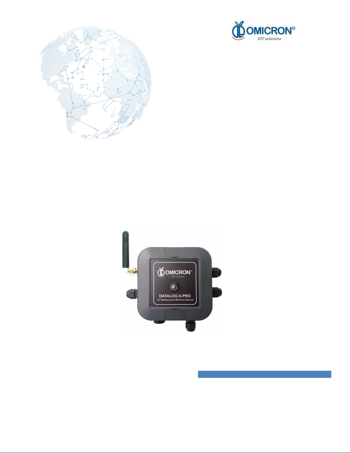
The internet of things (IoT) multisensor wireless device Datalog X-PRO is designed for remote
monitoring of multiple processes requiring high safety and measurement precision. In support of
your automation needs, it is fitted to receive up to 3 sensors of multiple types (listed in Section 5).
The system is delivered with a rechargeable Li-Ion Battery, necessary means to attach the Main
Unit enclosure to where is recommended, its AC/DC adapter, and all purchased wireless
communication modules. In accordance with the philosophy of the release, all complements
referred above can be prescinded, and remote data transmission may be performed by different
popular wireless technologies. Customers are also offered memberships for the use of a platform
for remote monitoring and configuration, supported by the manufacturer. More detail can be
found ahead.
The device is delivered with the necessary means for its mounting, however, it may require
additional initial configuration regarding its sensors or wireless communication configuration.
After initial setup, additional configuration can be made remotely by authorized personnel.
Parameter setting can be password protected.
2.1 Features
Datalog X-PRO has been thought to easily monitor and deliver data about the evolution of the
processes is embedded into. As such, it relies on a series of functionalities, tools and
characteristics, set to offer the user the desired comfort.
Among these, it is worth to highlight the direct link that devices have with Centriomega® Remote
Monitoring Platform through their wireless communication modules: a platform accessible from
any computing device enabled for internet navigation (PC, tablet, smartphone).
Said platform facilitates remote configuration and monitoring tasks, keeps graphic record of the
variables of interest, indicates their maximum and minimum admissible limits, generates alarm
events with visual indications, sends external warning messages through e-mail, SMS, and
Telegram messages, keeps historical record of the evolution of each registered variable, corrective
actions and comments taken when alarms have occurred.
Relevant features include:
➔Wi-Fi®, Sigfox® modules for wireless transmission.
➔Remote monitor; namely PC, Tablet or Smartphone.
➔Historical data records on Centriomega® Remote Monitoring Platform.
➔Email, SMS, Telegram and Webhook notifications.
➔Off-line temporary storage, in case of network connection failure.
➔Remote parameter configuration.
www.omicroning.co March 2020
8

2.2 Datalog X-PRO Insight: Parts
Figure 2-1 Overview of uncovered Datalog X-PRO
1. Main board (P/N X-PRO1.0 BOARD): The base board takes care of the multiple detected
sensors and delivers data to the communications module. This part includes main supply and
battery terminals; ports for 3 sensors and the chosen communications module; as well as an
in-built accelerometer.
2. Communication module (P/N X-PRO1.0-Sigfox): It is responsible for the wireless transmission
of data, in real time, to any platform that allows remote monitoring of the process.
Communication modules are connected to Remote Monitoring System by default, but they
could be ordered to correspond to another platform.
May be:
Detachable board Sigfox Ready, RC2 902 – 905Mhz / RC4 920 -923Mhz, 22dBm ERP.
Inbuilt Wi-Fi® module (IEEE 802.11) 2.4 GHz transmission.
Figure 2-2 Sigfox communication module.
www.omicroning.co March 2020
9

3. Sensor interfaces (for part numbers, refer to Appendix C or to Datalog X-PRO Datasheet):
These terminals allow binding of external sensors, chosen by the user. Specifications and
requirements for the sensors that these interfaces receive are listed below. Every interface has
an in-built light indicator to mark whether a sensor is properly operating or not.
Figure 2-3 Sensor Interface.
4. Battery (with reference Ultralife UBBP01): 3.7 V Lithium-Ion Battery. Powers the monitoring
and transmission system when main supply is off.
www.omicroning.co March 2020
10

Section 3: Mounting Guidelines
To properly mount the system, please consider the instructions and suggestions given in the
following chapters. Plan all wiring before installing Datalog X-PRO. Also consider the cabinet
space, hardware dimensions and rated environmental conditions. Use good wiring practices to
minimize problems that may occur due to electrical interference.
Prevent metal fragments and pieces of wire from dropping inside the enclosure of
any Datalog X-PRO Main Unit or accessories. If necessary, protect the components
during installation and wiring. Ingress of such fragments and chips may cause a fire
hazard, damage or malfunction of the device.
Main Unit enclosure is a standard network ASA plastic box, with brackets for pole mounting, or
covered perforations for wall mounting; its details are listed in 3.2.1.
NOTE:
The system should be installed with all peripherals attached, to mount the assembly as a single
block. It is strongly recommended to install the antenna so that its axis is vertical with respect to
the ground, as this favors the range of the signals transmitted by the device.
Consider clearing a square area, of 25cm at each side, in the plane in which Datalog X-PRO
needs to be installed. Mount the system near the center of said clear space, so to leave enough
margins to comfortably install its peripherals.
3.1 Environmental Considerations
Device’s Main Unit and sensors are suited to be used in indoor/outdoor wet locations, since their
cases and probes are offered with IP67 protection: as such, they're waterproof and dust-proof, as
well as UV resistant. Environmental limits set for its operation are as follow:
●Altitude up to 2600 m.
●Temperature: 41°F – 104°F (5°C to 40 °C)
●Maximum relative humidity: 100%
●Pollution degree: 2
Locate Datalog X-PRO and all related components away from AC power/motor
wiring and sources of direct heat output such as transformers, heaters, large
capacity resistors, or shock and vibration sources. Avoid using the device in
areas where chemicals or flammable gases are present to minimize any risk of
ignition.
www.omicroning.co March 2020
11

3.2 Dimensions
3.2.1 Main Unit Enclosure
The Main Unit enclosure is a standard network ASA squared plastic box. Its dimensions are
indicated by the following schemes:
Figure 3-1 Main Enclosure elements
Datalog X-PRO enclosure elements
1
Top cover
2
Bottom base
3
Blind lids
4
Gasket
www.omicroning.co March 2020
12

Figure 3-2 Main Enclosure Dimensions
Dimensions in mm. Dark Grey enclosures made from ABS UL94-V0 plastic for high flammability
rating.
3.2.2 Antenna
The system uses an external helical antenna to reinforce the transmissions of its
telecommunications module. This peripheral component requires the most amount of clear space.
Its dimensions are shown in the following diagram:
Figure 3-3 Antenna Dimensions
3.2.3 Protective Valve
The user can order Datalog X-PRO with a protective vent accessory (P/N PFM-12) if plans to use
the device in harsh environmental conditions, such as outdoors:
●The protective valve prevents ingress of a variety of elements, such as water, dust or
other particles, while allowing water vapor molecules to diffuse through its microporous
membrane.
●The valve equalizes pressure and reduces condensation by allowing air to flow in and out
of the sealed enclosures.
www.omicroning.co March 2020
13

●The protective valve has IP68 protection rating (can be submerged in water 2m/60min)
and -40°C ~ 125°C operating temperature range.
Figure 3-4 Protective Valve
3.3 Mounting Indications
3.3.1 Main Unit
To secure Main Unit enclosure to a wall:
1. Find the mounting holes covered by the blind lids at opposite borders of the Main Unit
enclosure. They might be easier to locate after reviewing section 3.2.1.
2. Prepare the surface on which the Main Unit will be placed, taking into account the
distance between the holes previously found.
3. Use M3 screws (and nuts, washers, or plastic anchors, if needed) to fix the device where is
required.
To mount Main Unit on a pole:
1. Find the mounting holes covered by the blind lids at opposite borders of the Main Unit
enclosure. This might be easier after reviewing the previous section.
2. Attach the pole mounting bracket accessories that come with the delivery to the Main
Unit, using the screws provided by the manufacturer.
3. Finally, fasten the Main Unit to its pole using proper mounting straps.
www.omicroning.co March 2020
14

Figure 3-5 Reference example of similar device mounted in a pole
NOTE:
Remember that, since Datalog X-PRO operates with sensors and accessories attached, it is
recommended to leave enough space around the Main Unit to let it hold comfortably its
peripherals; as shown in the diagram below (dimensions in mm):
Figure 3-6 Recommended free space around Datalog X-PRO
www.omicroning.co March 2020
15

Section 4: Electrical Installation Foreword
Consider implementing safeguards independent to Datalog X-PRO when designing the wiring and
grounding plans for your application. This helps to assure optimum system operation, provides
additional electrical noise protection for your application and the Datalog X-PRO, and prevents
any malfunction on the process due to unexpected operating failures, to which any electronic
system is susceptible.
4.1 Power Requirements
Among other hardware and firmware protections, Datalog X-PRO is protected against power
interruptions through its battery; which can provide power for up to 180 days, depending on the
sensors implemented and the period between messages sent to a remote platform, aiming to
keep safe monitoring and storage of data. The user may consider using the Datalog X-PRO
disconnected from a power source and recharging the device when the battery is almost empty.
Always observe the following safety instructions:
●Connections must be made only in the complete absence of line voltage.
● If over-voltage is expected, surge arresters should be used.
●The power adapter provided with the equipment (P/N GSM06U12-P1J) is
only for indoor use. Use only a safety-certified power adapters or an
Industrial Power Supply with dual insulation between the primary and
output for powering the unit. The power supply output rating must be
limited to 6-24V DC, 0.5A for a single Datalog X-PRO, and not to be
connected to a AC or DC distribution network.
●For outdoor use, the user could use a safety-certified and waterproof
approved Solar Panel (not provided); the output rating must be limited to
6-24V DC, 0.5A for a single Datalog X-PRO.
In any case, a 0.5A 6W fuse and circuit breakers should be used between
the power supply and the device.
www.omicroning.co March 2020
16

4.2 Electrical Ratings
Main Unit Ratings (X-PRO1.0 BOARD):
• Rated main input voltage: 6 to 24VDC.
• Max. Electric Current: 0.5A.
• Overvoltage Category: II.
Battery Ratings (P/N UBBP01):
• Rated Voltage: 3.7VDC.
• Power Rating: 1800 mAh.
• Type: LiPo.
AC/DC Adapter Ratings (P/N GSM06U12-P1J):
•Input: 85 ~ 264VAC (Nominal: 110 to 220 VAC ± 10 %), 47 ~ 63Hz (Nominal: 50 to 60 Hz), 0.18A -
100VAC, Max 30A / 230VAC.
• Rated Output: 12V±5.0%, 0 – 0.5A.
• Power Rating: Max. 6W @ 12VDC.
Exceeding the voltage ranges defined for the power supply could cause damage
or unpredictable operation, which could result in death or severe personal injury
and/or property damage. To avoid any risk, Datalog X-PRO manufacturer could
be reached to receive further assistance on how to properly connect the
equipment. Remember that Contact Information is provided at the beginning of
this document.
4.3 Connection procedure
●Perform system installation while Datalog X-PRo is turned off, and its
battery is unplugged.
●It is recommended to use UL listed products for connections and
electrical protection.
The Datalog X-PRO is provided with a cable connected to its internal power terminal, passed
www.omicroning.co March 2020
17

through its cable gland for supply cables; so the user can use this cable to connect a 6 to 24 V DC
power supply or an appropriate Solar Panel (not supplied). Alternatively, and only for indoor use,
the user can connect the device to a 12V DC power adapter (supplied). Follow the next directives
for the different options.
4.3.1 Indoor Use: Connection with Power Adapter (Supplied)
1. Connect the adapter´s male plug into the female jack socket provided (See figure 4-1).
2. Connect the power adapter to a wall mains power 110 VAC-220 VAC, 50-60Hz.
Figure 4-1 Jack Connection
4.3.2 Outdoor Use Connect to a Solar Panel (Not Provided)
●Review diagrams thoroughly before installation. Support on electrical
wiring handbooks, or have your device connected by a qualified licensed
electrician.
●All electrical connections must be in accordance with local codes and
ordinances. If you are unfamiliar with methods of installing electrical
wiring, secure the services of a qualified electrician.
1. Unscrew the jack socket attached to the power cable of Datalog X PRO.
2. Remove approximately 1-in. (2.5 cm) of said power cable mantle and strip approximately 0.5-in.
(1.25 cm) off the edge of each conductor.
3. Connect the prepared cables to the output of a fusible DC disconnect switch. If the user chooses
not to use a fusible DC disconnect switch, it is recommended to use fuse links between the DC
disconnect switch output and the power input of the Datalog X PRO.
www.omicroning.co March 2020
18

The following image illustrates how to connect the referred protection and disconnection
elements to the Datalog X-PRO and the solar panel:
Figure 4-2 Scheme of Installation of the Datalog X-PRO with a Solar Panel
Remember that positive DC disconnect switch terminal should be connected to Datalog X-PRO´s
red power cable, and that negative DC disconnect switch terminal should be connected to Datalog
X-PRO´s black power cable end.
Besides environmental limits set for Datalog X PRO, fuse links must be rated for 500mA/24VDC.
Implemented DC disconnect switch and fuse enclosure must be suited for outdoor use.
4. Follow the guidelines of the solar panel manufacturer for its mounting.
5. Loosen the terminal block screws located inside the Solar Panel terminal box.
6. Connect DC disconnect switch to mounted Solar Panel.
Remember to use UL approved cables to link all components and necessary wiring practice to
assure electrical safety.
NOTE:
It is recommended to install the DATALOG X-PRO below the Solar Panel (See figure 4-3), since
this can prevent overheating of the equipment caused by direct sunlight over it.
It is recommended to cover the terminal box of the solar panel with a layer of silicone after
mounting and connecting it, to ensure its protection against the ingress of water or dust.
Remember that: PV Disconnect device must be suitably located and easily reachable. Also, said
device must be marked as the disconnecting device for the monitoring system.
www.omicroning.co March 2020
19

To avoid the overheating of Datalog X-Pro caused by solar radiation directly over
it, it is recommended to install the device vertically and at the shadow of the
solar panel (See figure 4-2).
Make sure that the IP67 protection of the the Solar Panel or the Datalog X-PRO
does not get affected or impaired by the mounting.
Figure 4-3 Reference Installation of the Datalog X-PRO with a Solar Panel
www.omicroning.co March 2020
20
Table of contents
Popular Accessories manuals by other brands

Franklin
Franklin DELUXE 3 POSITION BATTING TEE Assembly instructions

Sygonix
Sygonix 2267531 operating instructions

Pfannenberg
Pfannenberg DTS 3241 quick guide

schmersal
schmersal RSS260-123456 manual

Viking
Viking DDWB301CRSS installation instructions

ROSE DISPLAYS
ROSE DISPLAYS ANOFRAME VERSAMOUNT CEILING ANCHORS SQ manual

Bresser
Bresser 88-33000 operating instructions

Thermo Scientific
Thermo Scientific Ramsey MINI CK100 Operating and service manual

NEW BRUNSWICK SCIENTIFIC
NEW BRUNSWICK SCIENTIFIC CO28IR Guide to Operation

Honeywell
Honeywell RDWL313A2000 Installation and operation guide

Optex
Optex ViiK Exposed Type OVS-02GT Series installation instructions

Bosch
Bosch IVAS operating instructions