SEVERE PERSONAL INJURY AND PROPERTY DAMAGE CAN RESULT FROM IMPROPER INSTALLATION OR
ASSEMBLY. READ THE FOLLOWING WARNINGS BEFORE BEGINNING.
If you do not understand the instructions or have any concerns or questions, please contact us 24/7 at 877.PLUGD.IN
(877.758.4346).
Do not install or assemble if the product or hardware is damaged or missing. If you require replacement parts please call
877.PLUGD.IN (877.758.4346).
FOR WALL MOUNTED PRODUCT: This product has been designed for use on a vertical wall constructed of wood studs
or solid concrete. Wood studs being defined as a wall consisting of a minimum of 2” x 4” studs with a maximum of 24”
stud spacing and a minimum of 16” stud spacing with a maximum of ½” inch of wall covering (drywall, lath, plaster). For
safe installation, the wall you are mounting to must support 4 times the weight of the total load (flat panel and wall
mount). If not, the surface must be reinforced to meet this standard. The installer is responsible for verifying that the
wall structure/surface and the anchors used in the installation will safely support the total load. Do not use this product
for any application other than those specified by OmniMount.
This product may contain moving parts. Use with caution.
PRODUCT CARE: To clean this product, wipe with a damp cloth and mild soap solution. Dry the product with a separate clean
cloth. Glass surfaces may be cleaned with a quality glass cleaning solution and paper towels. Never use abrasive chemicals or
household cleaners on materials surface, doing so may result in fading, discoloration, cracking or peeling of veneer. To prolong
material finish, avoid the following: Direct heat applied to surfaces, Above average room temperatures, abrasive cleaner, Direct
sunlight for prolonged periods, Liquid spills not removed properly, household cleaners.
WARNING!
sunlight for prolonged periods, Liquid spills not removed properly, household cleaners.
DO NOT EXCEED THE MAXIMUM WEIGHT CAPACITY FOR THIS PRODUCT.
LA INSTALACIÓN O EL MONTAJE INAPROPIADOS PUEDEN PROVOCAR LESIONES, DAÑOS MATERIALES O
INCLUSO LA MUERTE. ANTES DE COMENZAR, LEA LAS SIGUIENTES ADVERTENCIAS.
Si las instrucciones no le resultan claras o si tiene alguna duda o pregunta, comuníquese con un instalador calificado. Si
el producto o el hardware está dañado o no se le envió alguna pieza, no realice la instalación ni el montaje. Si necesita
piezas de repuesto, comuníquese con el servicio de Atención al cliente llame al 877.PLUGD.IN (877.758.4346).
PARA MONTAJE EN LA PARED:Este producto está diseñado para ser instalado en paredes verticales con paneles de madera
u hormigón. Se define a los paneles verticales como una pared que consiste de un mínimo de paneles de 5 x 10 cm con un
espacio entre paneles máximo de 60 cm y un espacio mínimo entre paneles de 41 cm, con un máximo de cobertura de pared
(hoja de yeso, listón, yeso) de 13 mm. Para realizar una instalación segura, la pared elegida debe ser capaz de soportar 4 veces
el peso de la carga total (montaje plano del panel y de la pared). De lo contrario, deberá reforzar la superficie para que cumpla
con este requisito. El instalador es el responsable de comprobar que la estructura/superficie de la pared y los tacos que se utilizan
en la instalación soporten la carga total de manera segura.
Este producto puede contener componentes móviles. Úselo con precaución.
CUIDADO DEL PRODUCTO: Para limpiar el producto, utilice un paño humedecido con una solución de agua y jabón poco
concentrada. Para secarlo, utilice otro paño que esté limpio. Las superficies de vidrio pueden limpiarse con un limpia vidrios de
¡ADVERTENCIA!
P2
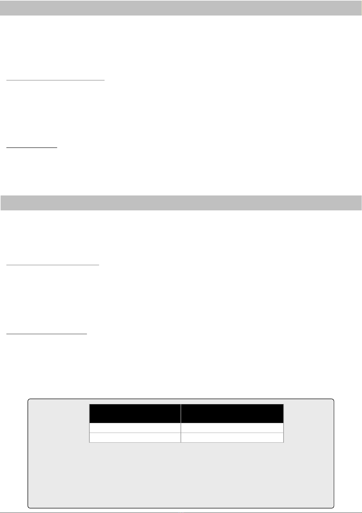
MAXIMUM WEIGHT CAPACITY
MÁXIMA CAPACIDAD DE PESO
POUNDS (LBS) / KILOGRAMS (KG) LIBRAS
(LB) / KILOGRAMOS (KG)
SINGLE STUD 25 (LBS) / 11.3 (KG)
16” ON CENTER STUD 35 (LBS) / 15.8 (KG)
USE WITH COMPONENTS LARGER THAN THE MAXIMUM WEIGHT AND/OR
SCREEN SIZE MAY RESULT IN INSTABILITY CAUSING POSSIBLE INJURY.
EL USO DE LA MONTURA CON COMPONENTS MÁS GRANDES QUE EL PESO O EL
TAMAÑO MAXIMO PUEDEN PROVOCAR LA FALLA DE LA MONTURA Y PROVOCAR
LESIONES.
buena calidad y toallas de papel. Nunca utilice limpiadores domésticos o productos químicos abrasivos para limpiar las
superficies, ya que el revestimiento podría decolorarse, agrietarse o desprenderse. Para que el acabado del material dure más,
evite lo siguiente: exposición de las superficies al calor directo, temperatura ambiente superior a la media, limpiadores abrasivos,
exposición directa a los rayos del sol por períodos prolongados, limpieza insuficiente de líquidos derramados, limpiadores
domésticos.
NO EXCEDA LA CAPACIDAD DE PESO MÁXIMA PARA ESTE PRODUCTO.


