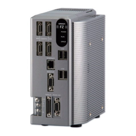
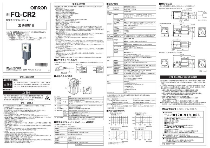
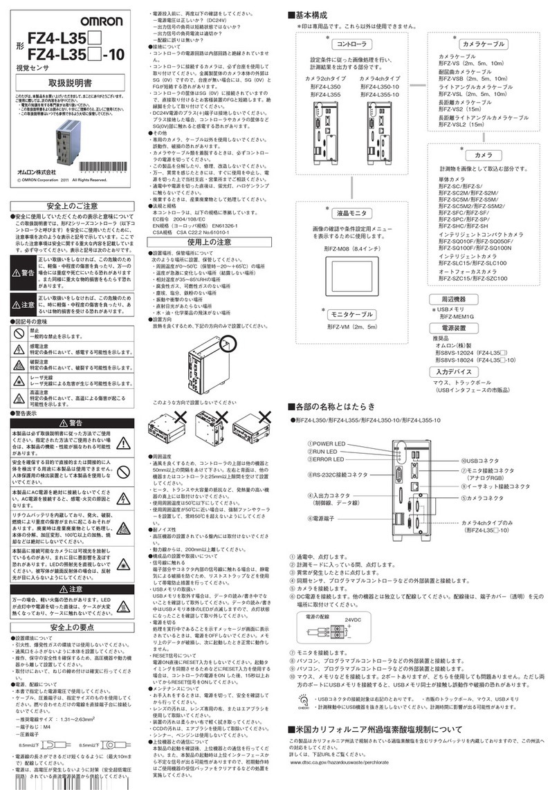
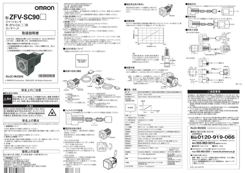
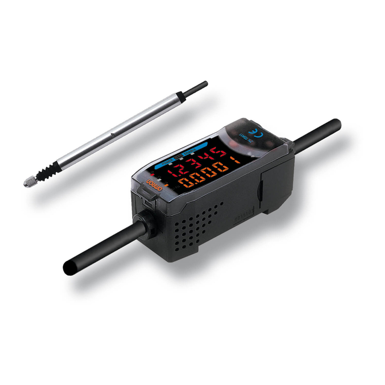
Omron F500 - User manual

F500
C-55F500
Vision Sensor
F500
Network-compatible
Sensor supports
everything from high-
precision detection to
production and
quality control
Features
The F500 enables high-precision inspections and measurements in the factory and then goes
further to support easy construction of a production and quality control system for quality
traceability.
High-precision Sensing
1-million-pixel Digital Interface Camera
Clear images are obtained by greatly reducing noise in high-
resolution video signals.
User Customization for Even Simpler Operation
Various applications are supported through features like flow
menus that flexibly handle even complicated applications and
macros that enable user programming.
A Wealth of Algorithms to Achieve High-precision
Measurements
High-precision measurements are achieved through original
algorithms ideal for lowcontrast mark positioning, minute de-
fect detection, and much more.
Applications Software
Build Flexible Applications
The F500 provides OMRON's new menu system called Flow
Menus, which enable flexible measurements through menu
settings including multiple filtering operations and conditional
branches based on measurement results.
Easier to Use, Easy to Program
A Macro programming feature is provided to support mea-
surement functions by enabling screen customization, I/O in-
terface changes, measurement condition changes, and much
more. Macros can be easily programmed using a simple text
editor.
Storage for Production and Quality Control
Store inspection and measurement data for safe keeping.
Provide feedback to quality control data, or analyze the data
to improve quality. The stored data can be used in many
ways.
Large Storage Capacity
Approximately 200 images minimum can be stored right in the
Controller. Measurement images are stored without alteration
for future use, such as repeating measurements to check
measurement accuracy or attaching images to reports.
Remote Access and Operation
across a Network
Easily achieve a production and quality control system using
an IT environment that provides easy access to the production
site and operating status.
Remote Access and Operation
Data such as the operating status of the Vision Sensor and
images resulting from inspections can be remotely accessed.
Measurements, storage, and communications can be execut-
ed independently so that measurements will not stop even
during random remote access.
F502-EN2-04.book Seite 55 Dienstag, 26. Juli 2005 5:48 17

C-56 Vision Systems
Flexible User Customization for Any
Purpose
Benefits of Increased Resolution
Doubling the horizontal and vertical resolutions increases to-
tal resolution by a factor of four, enabling clear images for
small or complicated workpieces.
1-million-pixel Camera with Digital Interface
The video signal noise that hurt measurement precision has
been greatly reduced to enable inspections of minute foreign
matter or damage as well as highprecision positioning.
Partial Scan Function
Partial scans can be used to reduce the image reading time,
which is often the bottleneck in measurement processing
time.
Advanced Algorithms for High-precision Measure-
ments
Positioning
ECM Searches
Edge code models are used for pattern
searches. ECM searches are not easily af-
fected by deformation and dirt, and can thus
be very effective with low-contrast workpiec-
es.
EC Positioning
Model registration is not required for EC posi-
tioning. Searching is possible with shape in-
formation, such as "circle," "rectangle," or
"intersection." This achieves higher precision in measure-
ments than conventional pattern matching methods.
Reference data: Repeatability is within 1/20 pixel (OMRON test data)
Appearance Inspections
EC Defect
Geometric information is used to measure
minute defects or lowcontrast scratches in
the measurement object at high precision.
Stable detection is possible for applications
like measuring deformation in O-rings.
EC Circle Count
Circles are searched for based on a circle of
a specified size. Stable detection is possible
without undue influence by deformation or
dirt.
EC Circle Defect
Defects in circles, such as depressions and
scorching in molded items, can be easily
measured at high precision. The defect in the circle can be ex-
tracted even with a patterned background.
Reduced Work with Simple Operations
Zoom Function for 1-million-pixel Images
Zoom in to see detail clearly for easier setting and adjustment
(display enlargement supported).
High-speed Serial USB Interface
A USB interface simplifies high-speed communications be-
tween the Vision Sensor and a computer. Communications
can be used to handle measurement data, setting data, sys-
tem data, image data, and more.
Number of Pixels read Reading time
1,024 x 1,024 pixels 48.3 ms
1,024 x 512 pixels 27.6 ms
1,024 x 256 pixels 16.3 ms
1,024 x 128 pixels 10.7 ms
250,000 pixels (previous systems) 1 million pixels
Line Brightness Image from an
Analog Interface Camera
Line Brightness Image from a
Digital Interface Camera
Full Frame Reading Partial Reading
Setting Screen
ZOOM
Entire Screen Display Enlarged Display
Measurement Screen
ZOOM
F502-EN2-04.book Seite 56 Dienstag, 26. Juli 2005 5:48 17

F500
C-57F500
Networking to Access, Save, View and Edit Data
Batched Access and List Viewing of Logged Images1
Batched Access and List Viewing of Measurement
Data1
Log Production and Quality Control Information1
Managing and Transferring Setting Data1
Batch File Uploading1
Display and Edit Scene Data1
1Scheduled for release soon.
The data stored in
the Controller can
be displayed in
lists.
Links can be created to
spreadsheet software to
statistically process
measurement results or
display graphs. All
measurement data can be
saved for feedback to trend
management or to monitor
variations in measurement
data.
Macros can be used to total production
quantities, production information such as fault
rates, or NG products
according to the type of
inspection.
Files containing Vision Sensor
setting data (such as scenes
and system data) can be sent
and received.
The software version of the
Vision Sensor can also be
easily upgraded.
Batch Transfer
The data saved in the Con-
troller can be transferred
to a computer as a batch
upload. This function is
useful when determining
judgement values for initi-
al settings or to back up
data.
And because measure-
ments and communicati-
ons are executed indepen-
dently, files can be uploa-
ded without affecting the
Vision Sensor's measure-
ment operation.
Daily Report
Date:
Production quantity
Rate of operation
Daily Report
Date:
Production quantity
Rate of operation
Daily Report
Date:
Production quantity
Rate of operation
Production 15400 pcs.
Good products 14890 pcs.
NG products 610 pcs.
Scene data set in
Vision Sensors
connected to the
network can be
viewed and edited.
The scene data
displayed on the
computer can also
be printed.
F502-EN2-04.book Seite 57 Dienstag, 26. Juli 2005 5:48 17

C-58 Vision Systems
Remote Vision Sensor Operation in a Network Environment1
Vision Composer Net1
Download Setup Function1
Live Monitoring Function
Remote Operations
1Scheduled for release soon.
The Vision Composer
Net software connects
to OMRON Controllers
to monitor and control
operation, change
settings, and perform
other tasks.
Controllers can be
connected across
networks to monitor and
adjust Controllers in the
factory from an office.
Vision Composer Net
Factory LAN
Factory
Office
Router
Router
Monitor and
adjust Controllers
and manage data.
Vision Sensors in diffe-
rent production lines
can be easily set up.
Downloading is also
useful when changing
products or using new
programs.
Network Vision Sensor C
Network Vision Sensor B
Network Vision Sensor A
Transfer setting data
across the network.
Checking and switching Vision Sensor settings
Downloading new settings, and more
Management Host
Vision Sensor images can be
displayed in realtime on the
computer via Ethernet. (See
note 1.)
Live inspection images can
also be monitored remotely.
(See note 2.) And what's more,
the images from several
Controllers connected via the
network can be monitored
simultaneously on the
computer screen.
Note 1: The transfer speed of live
images depends on the network
environment.
2: Remote monitoring is not
possible through a firewall.
Live transfer
via Ethernet
LIVE
Monitor live images.
Vision Sensor measure-
ments can be started
and stopped and scene
data settings can be
specified from a remo-
te computer.
All operations that we-
re previously possible
from the Console can
be performed remotely
from a computer.
Remote
controller
Factory Office
F502-EN2-04.book Seite 58 Dienstag, 26. Juli 2005 5:48 17

F500
C-59F500
Applications
Connector and IC Lead Inspections
BGA Inspections
Positioning Liquid Crystal Boards
Printing Defects
Molded Product Defect Inspections
Ceramic Board Defect Inspection
Inspecting Electrolytic Capacitor Dimensions
Chip Capacitor Electrode Defect Inspection
High-resolution inspection over
a wide field of view is enabled
by using a 1-million-pixel high-
resolution camera.
And with macro functions, the
statistics on lead pitch data and
linear approximations of the
lead ends are easily performed.
Length
Pitch
No. of leads
Combining networking enables changing inspection devices, manag-
ing master data, and uploading statistical data files with macros.
High-resolution inspection over
a wide field of view is also ena-
bled by using a 1-million-pixel
high-resolution camera with
BGA inspection software.Var-
iant BGA processing is also pos-
sible.
Quality control data can be used effectively by storing inspection im-
ages in relation to lot numbers. Managing all of the product data on
the host computer makes frequent changes to settings much
smoother.
Number of balls
Deformed ball Offset ball
Incorrect
position Ball size
EC processing, based on an
original algorithm from OM-
RON, enables position inspec-
tions of low-contrast alignment
marks. And using a Digital Inter-
face Camera enables stable
processing.
Macros can also be used to
easily achieve original calibra-
tion methods, inspection data
calculations, and much more.
Managing productivity is also possible by saving and reviewing in-
spection images, detection data, and position compensation data.
Using a 1-million-pixel high-res-
olution camera provides high-
precision inspections over a
wide field of view.
Using macros enables saving
images and inspection data
classified by the type of fault.
For initial system startup, data to determine judgement values and
to troubleshoot problems can be accessed from a remote computer,
reducing costs to a minimum.
Misshapen products, as well as
contamination and scorching
around molded products, can
be detected. Setting is as easy
as specifying the circle size to
detect (i.e., the size of the de-
fects) on limit samples dis-
played on the monitor.
With macros, statistics on good products, NG products, and fault
rates for the inspections performed each day can be calculated and
logged in a Memory Card.
Image
Taken
Filtering
Again
Filtering
Again
EC Defect
Inspection
Inspect for cracks on the sur-
face of ceramic boards. Even if
uneven lighting or rough surfa-
ces show in the images, linear
aspects can be consistently de-
tected.
Using the flow menus enables
conversion to more stable in-
spection by repeatedly filtering
images.
The diameter of round workpie-
ces can be measured at multi-
ple points to determine if they
are round or not.
With macros, deviations in in-
spection values can be stored
in memory and statistics, such
as minimum values, maximum
values, and standard devia-
tions, can be calculated.
Even if the size of the inspec-
tion object changes, the size of
the inspection area adjusts to
the external size to enable
measurement. Misshapen prod-
ucts and contamination and
scorching around products can
be detected.
With macros, production statistics (e.g., number of good products,
number of NG products, and fault rates) can be calculated and moni-
tored onscreen.
F502-EN2-04.book Seite 59 Dienstag, 26. Juli 2005 5:48 17
C-60 Vision Systems
List of Processing Items
Processing
Items
Binary
Processing
Gray-scale
Processing
EC
Processing
Higher precision
Gray Search
(x-y: Pixel Level)
Precise Search
(x-y: Subpixel Level)
Rotation Search
(x-y- : Subpixel Level)
Circular Angle
BGA
Edge Position_1
Edge Position_8
(Number of areas
drawn differs.)
Edge Width
(Width between edges
measured.)
T-Edge Position
Density Defect #
Defect
Defect (Var. Box)
Fine Matching
Flexible Search
EC Circle Defect
EC Defect
Density Data
(Average and Deviation)
Gray Search
(x-y: Pixel Level)
EC Circle Count
Positioning
Gravity and Axis
Gravity and Area
Binary Defect
Labeling
Label Data
(counting possible)
Area (Var. Box)
ECM Search
EC Positioning
Presence and Direction Inspections
Appearance (Defect) Inspections
Dimensions
Applications Packages
The F500-UM Applications Software is used both with the F210 and F250.
Many other measurement functions are also supported by this software. For details, go to http://www.fa.omron.co.jp/sensing/
F502-EN2-04.book Seite 60 Dienstag, 26. Juli 2005 5:48 17
F500
C-61F500
Flow Menus
Complete Image Processing Items
Image Input
Position
Compensation
Branching Control
Measurement Support
Results Output
Results Display Display String
Display Measure
Display Judge
Positioning
Presence and
Direction Inspection
Appearance (Defect) Inspection
Dimension Inspection
Applications Package
Switch Camera
The camera can be selected when two cameras are
connected.
The camera image is read synced on an external
signal.
Filtering Again
Filtering can be performed many times for the same
image.
Changing Filtering
Filtering can be performed that is different from that
performed when the image was read.
EC Position Compensation
EC position compensation is effective for low-
contrast marks that vary in size.
Edge Position Compensation
Positioning is compensated based on the outline of
the workpiece found through edge
processing.
Binary Position Compensation
Positioning is compensated based on the center of
gravity and axis angle found using binary
processing.
Elapsed Time
The processing time to a specified point in the
process flow can be measured. This can be used
for the required processing, such as canceling
measurements for time delays.
Wait
The processing flow can be temporarily paused to
place processing on standby for a set period of time.
Trend Monitor
Measurement time can be displayed on a graph
along a time axis.
Set Unit Data
Setting data can be overwritten.
Calculation
Calculations, such as basic arithmetic, tangent,
cosine, and distance calculations, can be performed
on the measurement data found using
measurement functions.
Conditional Branching
Measurement conditions can be changed based on
measurement values and results.
DI Branching
Processing can be branched based on the input
status of the parallel interface.
End
End indicates the end of the process flow. (No
settings are required.)
Macros
Scroll
Images read using X,Y coordinates and angle data
found with measurement functions can be scrolled.
Reset Scroll
Images that have been scrolled can be reset to their
original positions.
Model Position Compensation
Positioning is compensated based on search points
found by matching with registered models.
Measurement
Memory Card Data
Measurement values can be output to a Memory
Card inserted in the Controller.
DO Judgement
The OK/NG judgement results can be output on the
parallel interface.
DO Data
Measurement values can be output as binary or
BCD data on the parallel interface.
Host Link Data
OMRON's PLC Host Link communications can be
used for measurement commands, judgement
results, measurement values, and other data
without special programming.
Data Logging
Measurement data and images can be stored inside
the Controller.
Normal Data
RS-232C communications can be used for
measurement commands, judgement results,
measurement values, and other data.
Display Item
Display Time
Display Figure
Display Line
Display Box
Display Circle
Display Cursor
F502-EN2-04.book Seite 61 Dienstag, 26. Juli 2005 5:48 17

C-62 Vision Systems
System Configuration
F500-LE25
F500-LE16
Memory Cards
F160-N64S (S) QM300-N128S
Applications Software
F500-UM2FE/UM2ME
Camera Cable
F500-VS 2M
PC Support Software
F500-CD2E
Network-compatible
Vision Sensor
F500-C10-ETN/F500-C15-ETN
1
2
3
4
Camera cable connector
(Up to two Cameras can be connected.)
Monitor connectors
Console connector
To computer via
LAN (Ethernet)
1-million-pixel Camera with
Digital Interface
F500-S1
12
4
3
High-resolution Lens
F500-LE50
Vision Composer Net
F160-N256S
10.4-inch LCD Monitor
F500-M10L
Consoles
F150-KP F160-KP
Optical Chart
40
5 10 20 30 50 100
200
300 500
100
200
300
1,000
2,000
3,000
5,000
500
F500-LE16
Extension Rings
t 35.0
t 30.0
t 25.0
t 20.0
t 15.0
t 10.0 t 5.0
t 0
t 40.0
t 20.0t 15.0 t 10.0
t 5.0
t 1.0
t 0
t 10.0
t 5.0
t 1.0
t 0
F500-LE50
F500-LE25
*Scheduled for release soon.
F502-EN2-04.book Seite 62 Dienstag, 26. Juli 2005 5:48 17
F500
C-63F500
Specifications
F500-C10-ETN / F500-C15-ETN
F500-S1
System Requirements for F500-CD2E Vision Composer Net
Connected Camera F500-S1
No. of connectable Cameras 2
Processing resolution 1,024 (H) x 1,024 (V)
No. of scenes 32 (Can be increased using Memory Cards)
Image memory function 35 images max
Storage 256 MB non-volatile memory
Operation and setting Measurement items installed using Applications Software. Menu operations used to combine
measurement items. Vision Composer Net can be used for operation and settings.
Menu language Japanese or English (switchable)
Serial communications USB series B: 1 channel
RS-232C/422: 1 channel
Network communications Ethernet 100Base-TX/10Base-T
Parallel I/O 11 inputs, 22 outputs
Monitor Interface Composite video output: 1 channel
S-VIDEO output: 1 channel
Memory Card interface Compact Flash card slot, 1 channel
Power supply voltage 20.4 to 26.4 V DC
Current consumption 2.1 A max. (with two F500-S1 Cameras connected)
Ambient temperature Operating: 0 to 55°C
Storage: -25 to 65°C with no icing or condensation
Ambient humidity Operating / Storage: 35% to 85% with no condensation
Dimensions 100 x 198 x 134 mm (W x H x D) (without connectors and other protrusions)
Weight Approx. 1.6 kg (Controller only)
Accessories Ferrite core for console (1), Setup Manual
Picture elements 2/3-inch CCD
Pixel size 6.45 µm (H) x 6.45 µm (W)
Shutter Electronic shutter, 10 shutter speeds (1/24 to 1/10,000 s), changed via menu
Partial function Four settings
Communication interface Conforms to Camera Link
Ambient temperature Operating: 0 to 50°C
Storage: -25 to 60°C
with no icing or condensation
Ambient humidity Operating / Storage: 30% to 85% with no condensation
Dimensions 50 x 40 x 90 mm (W x H x D) (without connectors and other protrusions)
Weight Approx. 270 g
Accessories Instruction Manual
CPU Pentium III 600 MHz min. (Pentium III 1 GHz min. recommended)
OS Windows 2000 Professional, Service Pack 3 or higher
Windows XP Home Edition, Service Pack 1 or higher
Windows XP Professional, Service Pack 1 or higher
Memory 192 MB min. (256 MB min. recommended)
Hard disk 200 MB min. available space
Monitor Resolution: 1,024 x 768 min.
Display colors: High Color (16-bit) min. (True Color (32-bit) min. recommended)
Network 10BaseT-compliant network (100Base-TX recommended)
Vision
Sensor
Controller F500-C10-ETN/F500-C15-ETN
Application
Software F500-UM Version 2.00 or higher
F502-EN2-04.book Seite 63 Dienstag, 26. Juli 2005 5:48 17
C-64 Vision Systems
Dimensions
48
ø4.8
ø12
29.7
20
135.5
2000
40
34
Mounting bracket
Monitor cable
(F150-VM)
285
225
(160.8)
(214)
(200)
274
(6.5) (42.5)
(209.8)
49
47 max.
214
(227.5)
(237.5)
50 min.
73
216±1
276±1
(17)
(40)
(19.1)
Console
F160-KP
Controller
F500-C10-ETN
F500-C15-ETN
(Unit: mm) (Unit: mm) (Unit: mm)
(Unit: mm)
Monitor
F500-M10L
Panel Cutout
Camera
F500-S1
4-M3,
depth 8
1/4-20 UNC
tap, depth 8
ø6 +0.1, depth 8
2-ridges,
R1
4-R2
C-mount
4-M3, depth 5
2
5
50
50
13 34±0.2
14±0.2
30±0.2
90
40
56
16
7.6
26
4011
4-M4,
depth 8
4-M4,
depth 8
4-ø20
76 33
60±0.4
173±0.5
8.50
41
4.8
190
43
(14.05)
8
78
15
100
10.4
134
Mounting board
thickness: 1.6 to 5
0
In the interest of product improvement, specifications are subject to change without notice.
ALL DIMENSIONS SHOWN ARE IN MILLIMETERS.
To convert millimeters into inches, multiply by 0.03937. To convert grams into ounces, multiply by 0.03527.
Cat. No. Z203-E2-03-X
Z203-E1-Cat04-02_F500.fm Seite 64 Montag, 12. September 2005 7:13 19
Table of contents
Other Omron Accessories manuals

Omron
Omron F150-3 - Instruction Manual

Omron
Omron FZ4-6 series User manual

Omron
Omron E2FQ User manual

Omron
Omron F3EM2-005 Series User manual

Omron
Omron E3X-DAC-S Series User manual

Omron
Omron E2EM User manual

Omron
Omron Z5FP-MC10 - SETUP User guide

Omron
Omron E3ZM-B - User manual

Omron
Omron Z4LB V2 User manual

Omron
Omron E3X-MDA11 User manual

Omron
Omron E2EQ User manual

Omron
Omron E3ZM - User manual

Omron
Omron MS4800E User manual

Omron
Omron MX2 COMPONET OPTION BOARD User manual

Omron
Omron CJ2*-CPU Series Instruction Manual

Omron
Omron ZW-C1*AT User manual

Omron
Omron E3X-NL - User manual

Omron
Omron fh series User manual

Omron
Omron E3S-CL1 User manual

Omron
Omron SYSMAC C200H User manual