manuals.online logo
Brands
  1. Home
  2. •
  3. Brands
  4. •
  5. Omron
  6. •
  7. Accessories
  8. •
  9. Omron ZG2 Series How to use

Omron ZG2 Series How to use

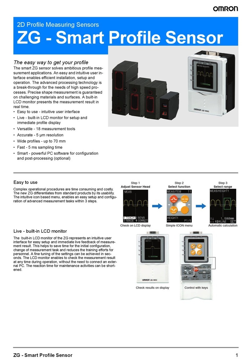
Smart Sensor
2-D Profile Measuring Sensor
ZG2
Short Manual
Setting tutorial
V1.0
ZG2 Short Manual
Overview
Extension cables:
ZG2-XC3CR: 3 m
ZG2-XC8CR: 8 m
ZG2-XC15CR: 15 m
ZG2-XC25CR: 25 m
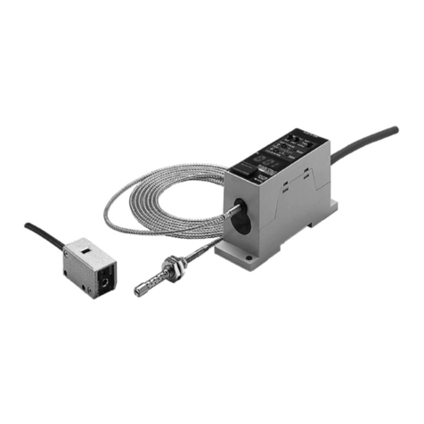
Sensor heads:
ZG2-WDS70
ZG2-WDS22
ZG2-WDS8T
ZG2-WDS3VT
0.5m or 2m cable length
Data Storage Unit:
ZG2-DSU41
ZG2-DSU11
Sensor Controller:
ZG2-WDC41A
ZG2-WDC11A
Parallel Output Unit:
ZG-RPD41
ZG-RPD11
RS232 cable:
ZS-XPT2 for PLC
ZS-XRS2 for PC
PC Setup Software „SmartMonitor ZG2“
and USB cable included with the ZG-WDCxxA
Controller
Link:
ZS-XCN
RS232
Max. total length: 27m
RS232
Overview
ZG2 Short Manual
Overview
(1)
(2)
(3)
(4)
(5)
(6)
(7)
(8)
(9)
(10)
(11) (12)
(13)
(14)
(1) Judgement Indicator (turns on if judgement result is O.K.)
(2) Laser Indicator (turns on while the LASER is powered on)
(3) Zero Reset Indicator (turns on while Zero Reset function is active)
(4) Trigger Indicator (turns on while trigger input is active)
(5) LCD Screen (color graphic LCD)
(6) Menu Switch (selects standard or expert menu)
(7) Mode Switch (selects set or run mode)
(8) Control Keys
(9) Sensor Head Connector
(10) Extension Connector (connects multiple controllers)
(11) USB connector
(12) RS232 connector
(13) Voltage / Current selector (for linear output)
(14) I/O cable (voltage supply and I/O terminals)
Overview
ZG2 Short Manual
Overview
Overview
Overview
Up to 2 ZG-WDCxx can be connected together using a Controller Link Unit ZS-XCN
in order to perform calculations with 2 sensor heads. Optionally 1 Data Storage Unit
ZG2-DSU can be attached to the left side.
Channel assigment is always as shown above (regardless of the presence
of a ZG2-DSUxx).
The Data Storage Unit ZG2-DSUxx can be used for logging measurement results,
logging profiles or storing bank data.
ZG2 Short Manual
Optional:
ZG2-DSUxx ZG2-WDCxx Optional:
ZG2-WDCxx
CH0 CH1 CH2
If 2 ZG2-WDCxx are used,
connect the USB cable
only to CH2
ZS-XCN
Overview
ZG2 Short Manual
Tutorial
This chapter shows step by step how to set up the ZG2 profile sensor to perform a
measurement. Below you can find the 7 steps to follow. More detailed description of
each step is given then on the following pages.
1) Initialization (optional):
Initialize the sensor as a first step to start with default values.
2) Mount the sensor head:
Mount the sensor head that you can see the yellow profile line on the LCD screen.
3) „Teach“ a profile:
The stored profile is used for the setting of the measurement region and position
correction.
4) Select a measurement item:
The ZG2 has19 different measurement items and 1 calculation item for flexible
inspection of all kinds of measurements.The ZG2 can perform up to 8 tasks at the
same time without increase of measurement cycle time.
5) Set the measurement region for the measurement item:
The functioning of measurement items is based on characteristic points which are
defined by a horizontal or vertical regions along the profile line.
6) Optimize the image settings regarding cycle time and accuracy:
The ZG2 has multiple modes for the control of the laser power as well as multiple
filters for image improvement.
7) Setup position compensation (optional):
The ZG2 can compensate horizontal, vertical and slope postion variations.
Tutorial
Setting Tutorial
1) Initialization:
To operate the menu you can either use the cursor keys and the set key
or the number keys.
1) Move first the menu switch to „EXP“ and then the mode switch to „FUN“.
2) Press key „4“ to select the System menu.
3) Press key „2“ to select „INIT“.
4) Confirm „YES“ with key „1“. Wait until the init process is finished.
5) Set the mode switch back to „RUN“.
6) Confirm saving the settings with the key „1“.
After initialization the laser power mode is set to „Multi Mode“ (s. page xx) and
the measurement item for task 1 to „Height1“. On the LCD screen you can see
the profile in real time. The red cross and the value in the bottom line shows the
result of task 1. Pushing the orange „Menu“ key toggles the lcd screen
first to the measurement result screen and then to the cycle time display/
resp. the screen saver.
ZG2 Short Manual
MENU
/VIEW
ESC
ADJ
FUN RUNSTD EXP SET
1 2
3 4
LD ON ZERO TRIG
T1
T2
T3
T4
LV: 1-320
HEIGHT1 B1T1
3.000mm
1) Set to EXP 2) Set to FUN
Corsor keys
Number keys
1 - 4
Menu switch Mode switch
Tutorial
ZG2 Short Manual
2) Mount the sensor head:
The ZG2 can measure up to 8 tasks at the same time. The settings for these 8 tasks is
stored in 1 bank. Up to 32 banks can be stored in the ZG2-WDC. The bank can
be changed in run mode via digital input terminal, RS232 or USB.
Move the sensor head
until the profile can be
seen on the LCD screen
in „RUN“ mode.
The red cross and the
mm-value on the screen
represent the actual
result of task 1:
The average height of
the whole profile.
Example: Width measurement of a
bar of a workpiece:
LD ON ZERO TRIG
T1
T2
T3
T4
LV: 1-320
WIDTH2 B1T1
3.000mm
Tutorial
ZG2 Short Manual
3) Teach: Store a profile in the internal memory
Move the mode switch to the „FUN“ position, push key „1“ for „Meas“, and
again key „1“ for „TEACH“. Confirm the teach process with the key „1“ for „YES“.
The stored profile is used for setting the measurement region as well for the setting
of the position compensation in later steps. The tought profile is stored until the next
teaching, also if the sensor is powered down. After teaching 2 additional menu items
appear on the screen above:
• 3 SENS
• 4 CORECT
Remark:
In the menu „2 IMAGE“ you can find all settings regarding sensitivity and laser
intensity. For a first evaluation we can leave these settings unchanged. As a final
step the IMAGE settings can be optimized for tuning the measurement times to be
faster.
MENU
/VIEW
ESC
ADJ
FUN RUNSTD EXP SET
1 2
3 4
LD ON ZERO TRIG
T1
T2
T3
T4
MEAS
2 IMAGE
1 TEACH
„Meas“
„Teach“
Tutorial
4) Select a measurement item:
In order to choose the measurement item for task 1 for the measurement of the width
of the bar you have to select the menu „3 SENS“:
Push key „3“ for selection of menu „3 SENS“, now the screen for the task selection
appears. Here you can select one of the 8 tasks by pushing the corresponding
number key and/or using the cursor keys and pressing the „SET“ key. The
selected task also is also shown in the bottom line of the screen. At this moment task
1 is preset with the default measurement item „HEIGHT1“ from the initialization
at the beginning.
ZG2 Short Manual
LD ON ZERO TRIG
T1
T2
T3
T4
MEAS
2 IMAGE
1 TEACH
3 SENS 4 CORECT
„3 SENS“
Task 1
Tutorial
Please select task 1 by pressing the key 1. Now the menu screen for the measurement
item apears. In the top line the current item is displayed. The menu allows to 1) select
a new item, 2) to set scaling for the output value, 3) to set the measurement region
manually and 4) set the measurement region automatically:
Press key 1 for the selection of „1ITEM“. Now you can select a new item from a set of
19 different items. Use the number and/or the cursor keys for the selection of the
desired item. For this tutorial please choose the „Width1“ item from page 4:
Press key 3 and then confirm the change of the item with key 1 for „YES“.
LD ON ZERO TRIG
T1
T2
T3
T4
MEAS/HEIGHT1
2 CUSTOM
1 ITEM
3 SCALE 4 AUTO
ZG2 Short Manual
Current item
Item
menu
Current task
Item
„Width1“
Tutorial
ZG2 Short Manual
5) Set the measurement region:
The sensor uses up to 4 characteristic points of the profile to calculate the
measurement result . For each point you have to define a horizontal region where the
sensor finds this characteristic point in RUN mode. This setting is done
with the profile which is stored with the teach process. Please take care that the
region settings and the position compensation settings are performed with the same
stored profile. The regions can be set automatically with menu „4 AUTO“ and
manually with „2 CUSTOM“. You can use first the auto function and the custom
setting for finetuning in a second step. (If the menu switch is set to STD the „4 AUTO“
menu is not available).
Please select „4 AUTO“ by pressing the key 4:
Now the „TRIMMING“ screen is displayed. You can move the red cross in the top
left corner of the green rectangular with the cursor keys. Continue with „SET“ and
then move the red cross in the bottom right corner, and again press „SET“.
The item „WIDTH1“ requires 2 characteristic points for calculationg the width.
You must trim the green rectangular so that the green dashed line cuts the 2 vertical
edges of the bar. After pressing „SET“ the second time, the Sensor displays the
result. If you are successful you get following screen:
Tutorial
LD ON ZERO TRIG
T1
T2
T3
T4
0LINE SET
TRIMMING
15.000mm
height-
coordinate
horizontal-
coordinate
ZG2 Short Manual
LD ON ZERO TRIG
T1
T2
T3
T4
MEAS/WIDTH1
2 CUSTOM
3 SCALE
1 ITEM 4 AUTO
P1 P2
Now all important settings are made und you can check the result in the RUN
mode: Move the mode switch to the „RUN“ position and confirm the settings with
key 1 for „YES“.
In RUN mode the sensor measures the width of the bar and shows the result in
the bottom line of the screen. The result is shown in red color if the result is above
the high threshold or below the low threshold. In this case also the corresponding
task LED is off. If the result is between the high and low threshold values it is
displayed in green color and the task LED is lit.
After pressing the orange „MENU/VIEW“ button the sensor displays a summary
of the results of 4 tasks at the same time.
LD ON ZERO TRIG
T1
T2
T3
T4
LV: 1 - 320
WIDTH1 B01T1
12.000mm
Tutorial
Current screen:
Bank 01
Task 1
current measurement
item
Measurement
value
LED for digital output
of task 1

Other manuals for ZG2 Series

3

Other Omron Accessories manuals

Omron E3Z-H User manual

Omron

Omron E3Z-H User manual

Omron ZW-XC7 User manual

Omron

Omron ZW-XC7 User manual

Omron Large Cuff Operating instructions

Omron

Omron Large Cuff Operating instructions

Omron ZFV-C Installation manual

Omron

Omron ZFV-C Installation manual
Omron ZW-S7010 Operating instructions

Omron

Omron ZW-S7010 Operating instructions

Omron FQ SHORT User manual

Omron

Omron FQ SHORT User manual

Omron fh-3 series User manual

Omron

Omron fh-3 series User manual

Omron B5WC User manual

Omron

Omron B5WC User manual

Omron ZX1-LD User manual

Omron

Omron ZX1-LD User manual

Omron E32-D82F User manual

Omron

Omron E32-D82F User manual

Omron ZX-E - User manual

Omron

Omron ZX-E - User manual

Omron E32-L25T User manual

Omron

Omron E32-L25T User manual

Omron F160-2 -  2 User manual

Omron

Omron F160-2 - 2 User manual

Omron E2FM - User manual

Omron

Omron E2FM - User manual

Omron F3W-D User manual

Omron

Omron F3W-D User manual

Omron ZS-HLDS2T User manual

Omron

Omron ZS-HLDS2T User manual

Omron fz5 series User guide

Omron

Omron fz5 series User guide

Omron F160-2 -  2 User manual

Omron

Omron F160-2 - 2 User manual

Omron E3NW-ECT User manual

Omron

Omron E3NW-ECT User manual

Omron F3M-S Series User manual

Omron

Omron F3M-S Series User manual

Omron E3FS-10B4 2M User manual

Omron

Omron E3FS-10B4 2M User manual

Omron E2K-L User manual

Omron

Omron E2K-L User manual

Omron F3SJ-A series User manual

Omron

Omron F3SJ-A series User manual

Omron ZS Series Installation manual

Omron

Omron ZS Series Installation manual

Popular Accessories manuals by other brands

QUEST ELITE Snowdon Full item instructions and extended details

QUEST ELITE

QUEST ELITE Snowdon Full item instructions and extended details

ekwb EK-FC980 GTX Classy Backplate Installation and mounting manuals

ekwb

ekwb EK-FC980 GTX Classy Backplate Installation and mounting manuals

Flexifoil Camera Kite user manual

Flexifoil

Flexifoil Camera Kite user manual

PCB Piezotronics 353B52 Installation and operating manual

PCB Piezotronics

PCB Piezotronics 353B52 Installation and operating manual

Siemens 5WG1 258-2EB22 manual

Siemens

Siemens 5WG1 258-2EB22 manual

Roland GK-2A-Kit owner's manual

Roland

Roland GK-2A-Kit owner's manual

Carlon DH300 quick guide

Carlon

Carlon DH300 quick guide

POWER PROVE AC200 Operating and maintenance manual

POWER PROVE

POWER PROVE AC200 Operating and maintenance manual

epico E29 user manual

epico

epico E29 user manual

Philips OccuSwitch LRM1771 installation guide

Philips

Philips OccuSwitch LRM1771 installation guide

Grizzly H8174 instruction sheet

Grizzly

Grizzly H8174 instruction sheet

PCB Piezotronics ICP 106B Series Installation and operating manual

PCB Piezotronics

PCB Piezotronics ICP 106B Series Installation and operating manual

Adeunis RF AMR Series user guide

Adeunis RF

Adeunis RF AMR Series user guide

Hupfer SGR operating instructions

Hupfer

Hupfer SGR operating instructions

Emerson MICRO MOTION T-SERIES installation manual

Emerson

Emerson MICRO MOTION T-SERIES installation manual

Dini Argeo 3590EKR Series Technical manual

Dini Argeo

Dini Argeo 3590EKR Series Technical manual

alre HTFRA-010.101 manual

alre

alre HTFRA-010.101 manual

Siemens Milltronics BW100 instruction manual

Siemens

Siemens Milltronics BW100 instruction manual

manuals.online logo
manuals.online logoBrands
  • About & Mission
  • Contact us
  • Privacy Policy
  • Terms and Conditions

Copyright 2025 Manuals.Online. All Rights Reserved.