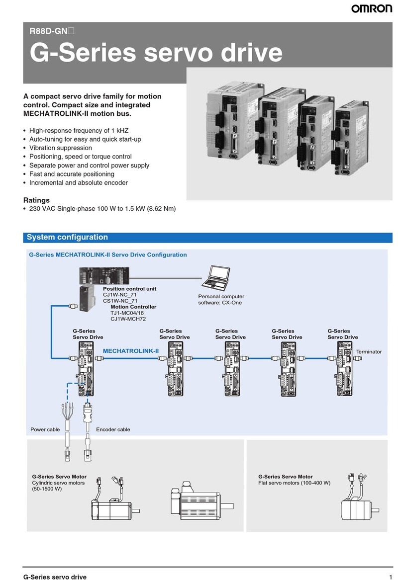
G-Series servo drive 3
Servo drive part names
I/O signal
Sequence input signal Emergency stop, 3 external latch signals, forward/reverse torque limit, forward/reverse run prohibit, origin prox-
imity, 3 general-purpose inputs
Sequence output signal It is possible to output three types of signals: positioning completed, speed coincidence, rotation speed detection,
servo ready, current limit, speed limit, brake release and warning signal
Integrated functions
Communications
RS-232
communications
Interface Personal computer
Transmission rate From 2400 to 57600 bps
Functions Parameter setting, status display, alarm display (monitor, clear, history), servo drive data tracing function, test
run/autotuning operations, real time trace, absolute encoder setting, default values function
MECHATROLINK
communications
Communications protocol MECHATROLINK-II
Transmission rate 10 Mbps
Data length 17 bytes and 32 bytes
Functions Parameter setting, status display, alarm display (monitor, clear, history), default values function
Automatic load inertia detection Horizontal and vertical axis mode. One parameter rigidity setting.
Dynamic brake (DB) Operates when main power OFF, servo alarm, overtravel or servo OFF
Regenerative processing Built-in regeneration resistor in models from 750 W to 1.5 kW. External regeneration resistor optionally.
Overtravel (OT) prevention function Dynamic brake, disables torque or emergency stop torque during POT and NOT operation
Emergency stop (STOP) Emergency stop input
Encoder divider function Optional division pulses possible
Electronic gearing 0,01<Numerator/Denominator<100
Internal speed setting function 8 internal speeds
Protective functions Overvoltage, undervoltage, overcurrent, overload, regeneration overload, servo drive overheat
Analog monitor Ouput The actual servomotor speed, command speed, torque and number of accumulated pulses can be measured u-
sing an oscilloscope or other device.
Panel operator Display functions A 2-digit 7-segment LED display shows the servo drive status, alarm codes, parameters, etc.
MECHATROLINK-II communications status LED indicator (COM)
Switches Rotary switch for setting the MECHATROLINK-II node address
Servo drive type R88D-GN@01H-ML2 02H-ML2 04H-ML2 08H-ML2 10H-ML2 15H-ML2
Applicable
servomotor
R88M-G@05030@/10030@20030@40030@75030@G1K020T@90010T@/ 1K030T@/
1K5@0T@
R88M-GP@10030@20030@40030@- - -
Control I/O connector (CN1)
Encoder connector (CN2)
G
IM
SP
COM
X10
3
2
1
0
ADR
AC SERVO DRIVE
X1
6
7
8
9
0
1
2
3
4
5
Display area
Rotary switches
for ML-II node address
ML-II comms
status LED indicator
RS-232 comms connector (CN3)
ML-II comms connector
(CN6A, CN6B)
Analog monitor check pins
(SP, IM, G)
Main-circuit power terminals
(L1, L2, L3)
Control-circuit power terminals
(L1C, L2C)
External regenerative resistor
connection terminals (B1, B2, B3)
Servomotor connection terminals
(U, V, W)
Protective ground terminals
