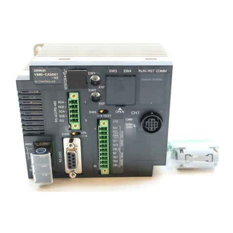
Model
V680-HAM42-PRT
PROFIBUSIDSlave
Observe the following precautions to ensure safe usage of the product.
1.
Installation and Storage Environment
・Do not use the Products in environments subject to oil.
2.
Installation and Removing
・Do not connect the power supply in reverse.
・Do not never use theAC power supply.
・Do not perform wiring incorrectly or short-circuit the load. Doing so may
result in rupture or damage from burning.
・Do not install the Products near any equipment that generates a large
amount of heat (such as heaters,transformers, and large-capacity
resistors).
・Make sure that all cable connectors with locking mechanisms are locked
before using the cable.
・If multipleAntennas are mounted near each other, communications
performance may decrease due tomutual interference. Refer to Reference
Data in Section 7 Appendices of User’s Manual and check to make sure
there is no mutual interference.
・To remove the Unit from DIN rail, catch a tool on the hook and gently
PRECAUTION FOR SAFE USE
1.
Installation and Storage Environment
Do not use or store the Product in the following locations.
・Locations subject to corrosive gases, dust, dirt, metal powder, or salt.
・Locations where the specified ambient temperature and ambient humidity
range is exceeded.
・Locations subject to extreme temperature changes that may result in
condensation.
・Locations where the product would be directly subjected to vibration or
shock exceeding specifications.
・Locations where liquid and foreign body might invade in this product
such as outside boards.
・Locationssubjecttocontactwithwater,oil,orchemicals.
2.
Installation
・The Products communicate with Tags using the 13.56-MHz frequency
band. Some transceivers, motors, inverters, and switching power
supplies generate noise that can affect communications with the Tags
and cause errors. If such devices are located near the Tags, always test
operation in advance to confirm whether the system will be affected.
・
Observe the following precautions to minimize the effects of normal noise.
(1)Ground all metal objects in the vicinity of the Products to 100Ωor
less.
(2)Do not use the Products near high-voltage or high-current lines.
・Always bundle the cables connected to the power supply terminals and
the ground terminal and connect the enclosed ferrite core
(ZCAT2032-0930 manufactured by TDK).
・Do not pull on the cables with excessive strength.
・Make sure that the ID Slave is provided with sufficient ventilation space.
・Please do not connect with the PROFIBUS connector excluding a
PROFIBUS cable.
・Turn OFF the Controller power supply before mounting or removing a
connector.
3.
Using
・Make sure the power supplied by the DC power supply unit is within the
rated power supply voltage (24 VDC +10%/−15%) before using the
Product.
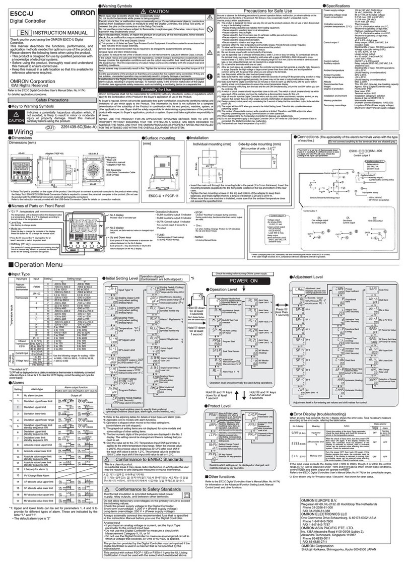
PRECAUTION FOR CORRECT USE
(Unit:mm)
・Node Address Switch
remove the Unit.
3.
Using
・Donotattempttodisassemble,repair,ormodifyanyProduct.
・Donotallowwaterorpiecesofwiretoenterfromopeningsinthe
case.Doingsomaycausefireorelectricshock.
・TurnOFFtheControllerpowersupplybeforemountingor
removinganAntenna.
・IfanerrorisdetectedinanyProduct,immediatelystopoperation
andturnOFFthepowersupply.ConsultwithanOMRON
representative.
4.
Cleaning
・DonotcleantheProductswithpaintthinner,benzene,acetone,or
kerosene.
5.
Disposing
・DisposeoftheProductsasindustrialwaste.
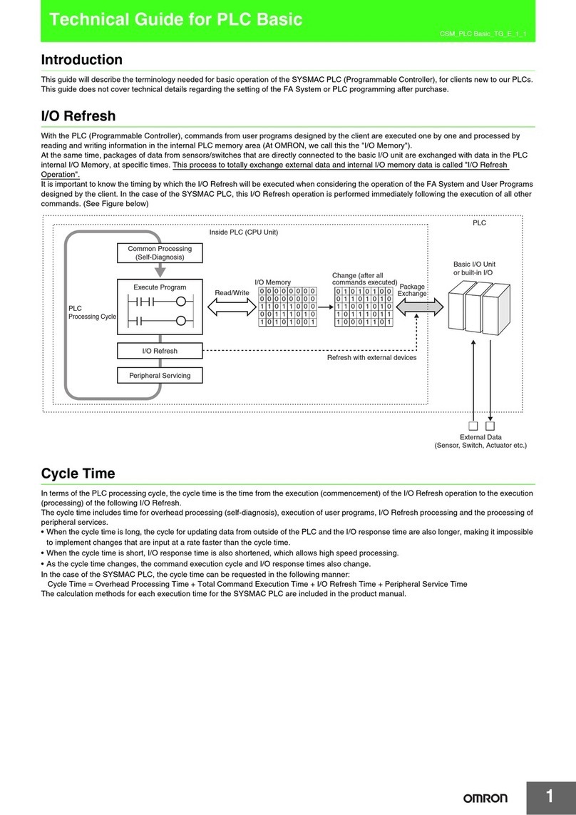
Specifications
Supply voltage 24 VDC (-15% to +10%)ripple(p−p)10% is contained.
Power consumption
4W max
Ambient operating
temperature
At operation:-10 to 55℃
(No freezing.There is no dew formation.)
At preservation:-25 to 65℃
(No freezing.There is no dew formation.)
At operation,At preservation:25 to 85%RH
(No freezing.There is no dew formation.
The ambient temperature of 85%RH is 40℃or less.)
Insulation resistans 20MΩmin.(with 500VDC megohmmeter)
Between power supply terminals (except for grand) and casing
Between power supply terminals (except for grand) and grand
Withstand voltage 1000VAC,50/60Hz,1min
Between power supply terminals (except for grand) and casing
500VAC,50/60Hz,1min
Between power supply terminals (except for grand) and grand
Vibration resistanse
10 to 150 Hz, double amplitude: 0.2 mm,Acceleration: 150m/s2,
with 10 sweep of 8 min each in 3 directions
Shock resistance
Mechanical durability: 150m/s2, 3times each in 6 directions
Dimensions 65 × 65 ×65 mm (excluding protruding parts)
Degree of protection
IEC60529Standard IP20 (Panel-mounting)
Material PC/ABS resin
Weight Approx. 150 g
Mounting method DIN rail
Ambient operating
humidity
Accessory
Ferrite core (TDK:ZCAT2032-0930) 1 pcs
Connector (PHOENIX CONTACT:FKC2.5/5-ST-5.08-RFAUM) 1 pcs
Instruction Sheet 1 sheet
Description of Regulations and Standard 1 sheet
Description
Setting method
Characteristic
Setting range
Setting method
Left rotary switch is a grider of ten.
Right rotary switch is a grider of one.
00〜63
The setting in the factory when shipping it is 00.
The node address of PROFIBUS is set.
・
Mode Switch
The operation mode is set.
Name
The setting is prohibited.(It becomes a mode setting error.)
No.
0
1
2
3
4
5
6
7
8
9
Run mode
The setting is prohibited.(It becomes a mode setting error.)
ー
ー
ー
ー
NOISE
TEST
RUN
ー
ー
ー
ー
ー
ー
The setting is prohibited.(It becomes a mode setting error.)
Normal operation.
Test lead execution on page 1 of 4 bytes
The environment measurement of the noise in the antenna surroundings .
Abbreviation Description
Communication Test
Noise measurement
ー
The setting is prohibited.(It becomes a mode setting error.)
The setting is prohibited.(It becomes a mode setting error.)
The setting is prohibited.(It becomes a mode setting error.)
ー
ー
ー
The setting is prohibited.(It becomes a mode setting error.)
SAFRTY PRECATIONS
5
1
9
6
1
2
3
4
5
−
CNTR-P
RxD/TxD-P
−
DGND
Name
PINNo.
6
7
8
9
VP
RxD/TxD-N
−
−
−
Control signal for repeaters (direction control)
Receive/Transmit data - plus (B wire)
−
Data ground (reference potentia for VP)
Description
Supply voltage of the terminator resistance (5Vdc)
Receive/Transmit data - minus (Awire)
−
−
1.5
16
20 10
6 18
21.5
42
18.25
32.5
5.1
22.6
3-SWITCH
CONNECTOR
12-OPERATION
INDICATOR
65 55 5
65
4
12
CONNECTOR
CONNECTOR
65
28.5
(3.7)
(12)
35.2
5
4.8
9.5 dia.
(6.1)
Meaning of Signal Words
Warning
WARNING
TheseProductsarenotdesignedtobeusedeitherdirectly
orindirectlyinapplicationsthatdetecthumanpresencefor
thepurposeofmaintainingsafety.Donotusethese
Productsasasensingmeansforprotectinghumanlives.
InIndicatesapotentiallyhazardoussituation
which,ifnotavoided,willresultinminoror
moderateinjury,ormayresultinseriousinjury
ordeath.Additionally,theremaybesignificant
propertydamage.
WARNING
Meaning of Alert Symbols
Indicatesgeneralprohibitionsforwhichthereisno
specificsymbol.
1. Rating performance
2. Installation
3. Name and functions
4. Dimensions
Recommended DIN Track
OMRON PFP-100N2
(track length: 1m)
1. First hook the ID Slave on part A, then press the ID Slave in direction B to
mount it to the DIN Track.
2. To disconnect the ID Slave from the DIN Track, pull the mounting hook
downwards, and then lift the ID Slave upwards.
0
9
8
7
6
5
4
3
2
1
0
9
8
7
6
5
4
3
2
1
0
9
8
7
6
5
4
3
2
1
V680-HAM42-PRT
OMRON
OMRON Corporation
SOURCE : 24VDC 0.2A
MADE IN JAPAN
X10 1X10 0
MS
BF
T/R
NORM/ERR
7
3
6
2
5
1
4
0
NODE ADDRESS MODE RUN TEST
NOISE
(2)Data indicator (2colored LED)
DATA:DATA code (Green)
ERC:Error code (Red)
(3)Mode Switch
regulates function mode
(4)Node Address Switch
node address setting (00〜63)
(7)PROFIBUS connector
Connect to the PROFIBUS Master Unit
(5)Power supply terminal
24VDC power supply is supplied.
Attached connector type:FKC2.5/3-ST-5.08-RF
(PHOENIX CONTACT)
Use wire size of AWG 12-22 with strip length of
10 mm. Recommended source is S8VS-03024
(OMRON).
(6)Antenna connector
1
2
3
GND
0V
+24V
Name
1
2
PIN No.
3
Ground terminal
24 VDC input terminals
Function
(1)Status indicator
MS:Machine status
BF:Bus Failure
T/R:Transmission status
NORM/ERR:Communication status
Connectable Antennas
V680-HS63-W
V680-HS65-W
0
9
8
7
6
5
4
3
2
1
0
9
8
7
6
5
4
3
2
1
0
9
8
7
6
5
4
3
2
1
V680-HAM42-PRT
OMRON
OMRON Corporation
SOURCE :24VDC 0.2A
MADE IN JAPAN
X10 1X10 0
MS
BF
T/R
NORM/ERR
7
3
6
2
5
1
4
0
NODEADDRESS MODE RUN TEST
NOISE
DIN Track
End Plate End Plate
Mounting Hook
©OMRON Corporation 2 011 All Rights Reserved.
INSTRUCTION SHEET
Thank you for selecting OMRON product. This sheet pri-
marily describes precautions required in installing and
operatingtheproduct.
Beforeoperatingtheproduct,readthesheetthoroughlyto
acquiresufficientknowledgeoftheproduct.Foryourcon-
venience,keepthesheetatyourdisposal.
Cable length
Radiated magnetic
field strength
13,56MHz
maximum 20 dBμA/m at 10 meters
Suitability for Use
s
Omron Companies shall not be responsible for conformity with any standards,
codes or regulations which apply to the combination of the Product in the
Buyer’s application or use of the Product. At Buyer’s request, Omron will
provide applicable third party certification documents identifying ratings and
limitations of use which apply to the Product. This information by itself is not
sufficient for a complete determination of the suitability of the Product in
combination with the end product, machine, system, or other application or
use. Buyer shall be solely responsible for determining appropriateness of the
particular Product with respect to Buyer’s application, product or system.
Buyer shall take application responsibility in all cases.
NEVER USE THE PRODUCT FOR AN APPLICATION INVOLVING
SERIOUS RISK TO LIFE OR PROPERTY WITHOUT ENSURING THAT THE
SYSTEM AS A WHOLE HAS BEEN DESIGNED TO ADDRESS THE RISKS,
AND THAT THE OMRON PRODUCT(S) IS PROPERLY RATED AND
INSTALLED FOR THE INTENDED USE WITHIN THE OVERALL
EQUIPMENT OR SYSTEM.
See also Product catalog for Warranty and Limitation of Liability.
Oct, 2014
D
OMRON Corporation Industrial Automation Company
Contact: www.ia.omron.com
Tokyo, JAPAN
OMRON ELECTRONICS LLC
2895 Greenspoint Parkway, Suite 200
Hoffman Estates, IL 60169 U.S.A.
Tel: (1) 847-843-7900/Fax: (1) 847-843-7787
OMRON ASIA PACIFIC PTE. LTD.
No. 438A Alexandra Road # 05-05/08 (Lobby 2),
Alexandra Technopark,
Singapore 119967
Tel: (65) 6835-3011/Fax: (65) 6835-2711
OMRON (CHINA) CO., LTD.
Room 2211, Bank of China Tower,
200 Yin Cheng Zhong Road,
PuDong New Area, Shanghai, 200120, China
Tel: (86) 21-5037-2222/Fax: (86) 21-5037-2200
OMRON EUROPE B.V.
Sensor Business Unit
Carl-Benz-Str. 4, D-71154 Nufringen, Germany
Tel: (49) 7032-811-0/Fax: (49) 7032-811-199
Regional Headquarters
Manufacturer:
Omron Corporation,
Shiokoji Horikawa, Shimogyo-ku,
Kyoto 600-8530 JAPA N
TRACEABILITY INFORMATION:
Importe in EU :
Omron Europe B.V.
Wegalaan 67-69
2132 JD Hoofddorp,
The Netherlands
