manuals.online logo
Brands
  1. Home
  2. •
  3. Brands
  4. •
  5. Omron
  6. •
  7. Touch Terminal
  8. •
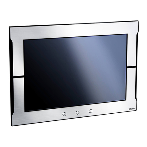
  9. Omron NA-series Operation and maintenance manual

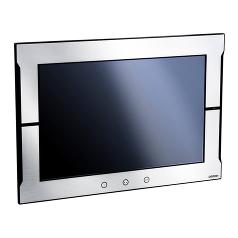
Omron NA-series Operation and maintenance manual

Precaution for Compliance with UL Standards and
CSA Standards
Notice to Users of NA series Programmable Terminal
(hereafter, “PT”) in the USA and Canada
Please use the following installation information instead of the general
information in the instruction manuals in order to use the product under
certified conditions of UL and CSA when the product is installed in the USA or
Canada. These conditions are required by NFPA 70, National Electrical Code
in the USA and the Canadian Electrical Code, Part I in Canada and may vary
from information given in the product manuals or safety precautions
OMRON Corporation
©OMRON Corporation 2014 All Rights Reserved
2296253-6B
■ Safety Precautions
Install the PT in Pollution Degree 2 Environment.
This equipment is suitable for use in Class I, Division 2,
Groups A, B, C, D OR non-hazardous locations only.
WARNING –
EXPLOSION HAZARD – Do not disconnect equipment
unless power has been removed or the area is known to
be non-hazardous.
WARNING –
EXPLOSION HAZARD - Substitution of any components
may impair suitability for Class I, Division 2.
Cet équipement convient à l’utilisation dans des emplacements de
Classe I, Division 2, Groupes A,B,C,D, ou ne convient qu’à l’utilisation
dans des endroits non dangereux.
AVERTISSEMENT -
RISQUE D’EXPLOSION – La substitution de
composants peut rendre ce materiel inacceptable
pour les emplacements de Classe I, Division 2.
AVERTISSEMENT -
RISQUE D’EXPLOSION – Avant de débrancher
l’équipement, couper le courant ou s’assurer que
l’emplacement est désigné non dangereux.
Precaution for Compliance with UL Standards and
CSA Standards
Notice to Users of NA series Programmable Terminal
(hereafter, “PT”) in the USA and Canada
Please use the following installation information instead of the general
information in the instruction manuals in order to use the product under
certified conditions of UL and CSA when the product is installed in the USA or
Canada. These conditions are required by NFPA 70, National Electrical Code
in the USA and the Canadian Electrical Code, Part I in Canada and may vary
from information given in the product manuals or safety precautions
OMRON Corporation
©OMRON Corporation 2015 All Rights Reserved
2296253-6B
■ Safety Precautions
Install the PT in Pollution Degree 2 Environment.
This equipment is suitable for use in Class I, Division 2,
Groups A, B, C, D OR non-hazardous locations only.
WARNING –
EXPLOSION HAZARD – Do not disconnect equipment
unless power has been removed or the area is known to
be non-hazardous.
WARNING –
EXPLOSION HAZARD - Substitution of any components
may impair suitability for Class I, Division 2.
Cet équipement convient à l’utilisation dans des emplacements de
Classe I, Division 2, Groupes A,B,C,D, ou ne convient qu’à l’utilisation
dans des endroits non dangereux.
AVERTISSEMENT -
RISQUE D’EXPLOSION – La substitution de
composants peut rendre ce materiel inacceptable
pour les emplacements de Classe I, Division 2.
AVERTISSEMENT -
RISQUE D’EXPLOSION – Avant de débrancher
l’équipement, couper le couran
t ou s’assurer que
l’emplacement est désigné non dangereux.
■Installation in a Panel
The device must be installed in an end-use enclosure, which may only be
opened by the use of a tool (tool secured enclosure). The panel in which
the PT will be mounted should be flat, with a smooth outer surface.
Supported panel thickness is 1.6 to 6.0 mm for UL Type 1 and UL Type 4X.
For UL Type 4X and panel thickness 1.6 to 4.5 mm using a High Pressure
Waterproof Attachment (PWA) is mandatory. Ensure the inside dimensions
for mounting NA5-W series with PWA are respected. There is a risk of
water ingress which may cause severe property damage. Outdoor use is
not permitted.
Model
PWA Partnumber
Model
PWA Partnumber
NA5-15W□□□□
NA5-15WATW01
NA5-9W□□□□
NA5- 9WATW01
NA5-12W□□□□
NA5-12WATW01
NA5-7W□□□□
NA5- 7WATW01
Install the PT using the following procedure:
1. Ensure the inside dimensions for mounting the PWA are respected.
Model
Inside dimensions
without PWA
Inside dimensions
with PWA
NA5-15W□□□□
420
⋅
291 mm
430
⋅
306 mm
NA5-12W□□□□
340 ⋅ 244 mm
348 ⋅ 259 mm
NA5- 9W□□□□
290
⋅
190 mm
298
⋅
203 mm
NA5- 7W□□□□
236 ⋅ 165 mm
236 ⋅ 178
mm
2. Create an opening in the panel.
Model
Dimensions Opening
NA5-15W□□□□
392
+1/-0
⋅
268
+1/-0
mm
NA5-12W□□□□
310 +1/-0
⋅
221 +1/-0 mm
NA5- 9W□□□□
261
+1/-0
⋅
166
+1/-0
mm
NA5- 7W□□□□
197 + 0.5/-0
⋅
141 +0.5/-0 mm
3. Ensure the rubber packing (gasket) is soft
and not damaged. Ensure the panel is not
dirty or warped and strong enough to hold
the PT.
4. Install the PT from the front of the panel.
■Installation in a Panel
The device must be installed in an end-use enclosure, which may only be
opened by the use of a tool (tool secured enclosure). The panel in which
the PT will be mounted should be flat, with a smooth outer surface.
Supported panel thickness is 1.6 to 6.0 mm for UL Type 1 and UL Type 4X.
For UL Type 4X and panel thickness 1.6 to 4.5 mm using a High Pressure
Waterproof Attachment (PWA) is mandatory. Ensure the inside dimensions
for mounting NA5-W series with PWA are respected. There is a risk of
water ingress which may cause severe property damage. Outdoor use is
not permitted.
Model
PWA Partnumber
Model
PWA Partnumber
NA5-15W□□□□
NA5-15WATW01
NA5-9W□□□□
NA5- 9WATW01
NA5-12W□□□□ NA5-12WATW01 NA5-7W□□□□ NA5- 7WATW01
Install the PT using the following procedure:
1. Ensure the inside dimensions at the rear allow mounting.
Model
Inside dimensions
without PWA
Inside dimensions
with PWA
NA5-15W□□□□
420
⋅
291 mm
430
⋅
306 mm
NA5-12W□□□□
340 ⋅ 244 mm
348 ⋅ 259 mm
NA5- 9W□□□□
290
⋅
190 mm
298
⋅
203 mm
NA5- 7W□□□□
236
⋅
165 mm
236
⋅
178mm
2. Create an opening in the panel.
Model
Dimensions Opening
NA5-15W□□□□
392
+1/-0
⋅ 268
+1/-0
mm
NA5-12W□□□□
310 +1/-0
⋅
221 +1/-0 mm
NA5- 9W□□□□
261
+1/-0
⋅ 166
+1/-0
mm
NA5- 7W□□□□
197 + 0.5/-0
⋅
141 +0.5/-0 mm
3. Ensure the rubber packing (gasket) is soft
and not damaged. Ensure the panel is not
dirty or warped and strong enough to hold
the PT.
4. Install the PT from the front of the panel.
5. Mount the PWA if UL Type 4X
protection level is required and the
panel thickness is 1.6-4.5 mm.
Slide the PWA over the rear of the
product until it is flat against the rear of
the panel.
6. Secure the PT to the panel using
the provided mounting brackets.
The number of mounting brackets depends of the model, as shown in
the following table. Tighten the Mounting Brackets evenly to a torque
of between 0.5 and 0.6 N·m to maintain water and dust resistance. If
the tightening torque exceeds the specified value, or the tightening is
not even, deformation of the front panel may occur.
Model
Number of Panel
Mounting Brackets
NA5-15W□□□□
8 locations
NA5-12W□□□□
6 locations
NA5-9W□□□□
4 locations
NA5-7W□□□□
4 locations
5. Mount the PWA if UL Type 4X
protection level is required and the
panel thickness is 1.6-4.5 mm.
Slide the PWA over the rear of the
product until it is flat against the rear of
the panel.
6. Secure the PT to the panel using
the provided mounting brackets.
The number of mounting brackets depends of the model, as shown in
the following table. Tighten the Mounting Brackets evenly to a torque
of between 0.5 and 0.6 N·m to maintain water and dust resistance. If
the tightening torque exceeds the specified value, or the tightening is
not even, deformation of the front panel may occur.
Model
Number of Panel
Mounting Brackets
NA5-15W□□□□
8 locations
NA5-12W□□□□
6 locations
NA5-9W□□□□
4 locations
NA5-7W□□□□
4 locations
■24-VDC Power Supply Wiring
1. Use the enclosed power supply connector to connect the power
supply to the PT. Connect a 24-VDC power supply type Class 2 to the
power supply connector. Use reinforced insulation or double
insulation type. Rated Power Supply Voltage: 24VDC (Allowable
range 19.2 to 28.8VDC)
2. Use the following wire size: AWG12 to AWG22.
3. Use the following tightening torque: 0.5 and 0.6 N·m.
Pin
No.
Signal Name
1
+24 V
2
0 V
3
FG
(Functional Ground).
■Operating Temperature
•The ambient operating temperature is 0° to 40°C when the mounting
angle is 0° or more and less than 45° to the horizontal.
•The ambient operating temperature is 0° to 50°C when the mounting
angle is 45° or more and 90° or less to the horizontal.
•The ambient operating temperature is 0° to 50°C when the mounting
angle is 90° or more and 135° or less to the horizontal.
Note: As the rubber packing (gasket) will deteriorate, shrink, or harden depending on
the operating environment, periodical inspection is necessary.
Mounting without PWA.

Other manuals for NA-series

9

This manual suits for next models

8

Other Omron Touch Terminal manuals

Omron NB3Q-TW**B series Instruction manual

Omron

Omron NB3Q-TW**B series Instruction manual

Omron NT11S User manual

Omron

Omron NT11S User manual

Omron WT30 User manual

Omron

Omron WT30 User manual

Omron NT20S User manual

Omron

Omron NT20S User manual

Omron DeviceNet DRT2-AD04 User manual

Omron

Omron DeviceNet DRT2-AD04 User manual

Omron NV Series Owner's manual

Omron

Omron NV Series Owner's manual

Omron NS-CXDC1-V1 User manual

Omron

Omron NS-CXDC1-V1 User manual

Omron NP3 Series Reference manual

Omron

Omron NP3 Series Reference manual

Omron NV Series User guide

Omron

Omron NV Series User guide

Omron NT631 Series User manual

Omron

Omron NT631 Series User manual

Omron NTXS User manual

Omron

Omron NTXS User manual

Omron NT2S-SF122B-E START V1.03 Instruction manual

Omron

Omron NT2S-SF122B-E START V1.03 Instruction manual

Omron NT20S-ST121B-EV3 User manual

Omron

Omron NT20S-ST121B-EV3 User manual

Omron NT20S User manual

Omron

Omron NT20S User manual

Omron NB3Q-TW00B User guide

Omron

Omron NB3Q-TW00B User guide

Omron NT31 Series User guide

Omron

Omron NT31 Series User guide

Omron PRT1-COM User manual

Omron

Omron PRT1-COM User manual

Omron DeviceNet DRT2-ID16S-1 User manual

Omron

Omron DeviceNet DRT2-ID16S-1 User manual

Omron Programmable Terminals NT631 User guide

Omron

Omron Programmable Terminals NT631 User guide

Omron NT612G Series User manual

Omron

Omron NT612G Series User manual

Omron NA-series Instructions for use

Omron

Omron NA-series Instructions for use

Omron NT11 - 01-2004 User manual

Omron

Omron NT11 - 01-2004 User manual

Omron Sysmac NA Series User manual

Omron

Omron Sysmac NA Series User manual

Omron DRT1-ID User manual

Omron

Omron DRT1-ID User manual

Popular Touch Terminal manuals by other brands

Symbol 2840 Series Supported equipment manual

Symbol

Symbol 2840 Series Supported equipment manual

Tailwind Spectra T1000 PEDPack Quick installation guide

Tailwind

Tailwind Spectra T1000 PEDPack Quick installation guide

Clover Flex quick start guide

Clover

Clover Flex quick start guide

Anitech Systems Media Pro 4000 Operation guide

Anitech Systems

Anitech Systems Media Pro 4000 Operation guide

DLoG XMT 5/7 manual

DLoG

DLoG XMT 5/7 manual

Siemens 3VT9100-4TC30 operating instructions

Siemens

Siemens 3VT9100-4TC30 operating instructions

Ingenico iCT220, iCT250 Download Steps

Ingenico

Ingenico iCT220, iCT250 Download Steps

Wow iq320 manual

Wow

Wow iq320 manual

Kollmorgen AKI-CDC-MOD-15T Installation guides

Kollmorgen

Kollmorgen AKI-CDC-MOD-15T Installation guides

HANTEL HTT-800A user guide

HANTEL

HANTEL HTT-800A user guide

Siemens SIMATIC NET PG PROFIBUS operating instructions

Siemens

Siemens SIMATIC NET PG PROFIBUS operating instructions

Midas Touch MTA-3080 user manual

Midas Touch

Midas Touch MTA-3080 user manual

Bilanciai D800 manual

Bilanciai

Bilanciai D800 manual

Mitsubishi Electric GOT 1000 Series General description

Mitsubishi Electric

Mitsubishi Electric GOT 1000 Series General description

Siemens 3RV1 operating instructions

Siemens

Siemens 3RV1 operating instructions

DIGM Technology GSM-TIT200A user manual

DIGM Technology

DIGM Technology GSM-TIT200A user manual

Carel TH Tune user manual

Carel

Carel TH Tune user manual

Beckhoff KL3042 operating instructions

Beckhoff

Beckhoff KL3042 operating instructions

manuals.online logo
manuals.online logoBrands
  • About & Mission
  • Contact us
  • Privacy Policy
  • Terms and Conditions

Copyright 2025 Manuals.Online. All Rights Reserved.