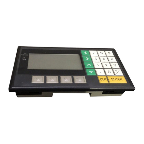
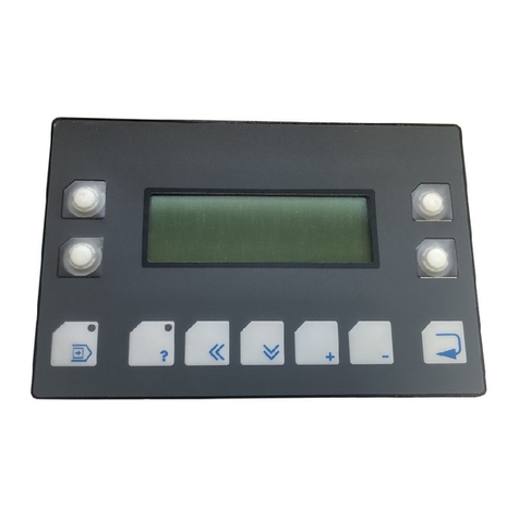
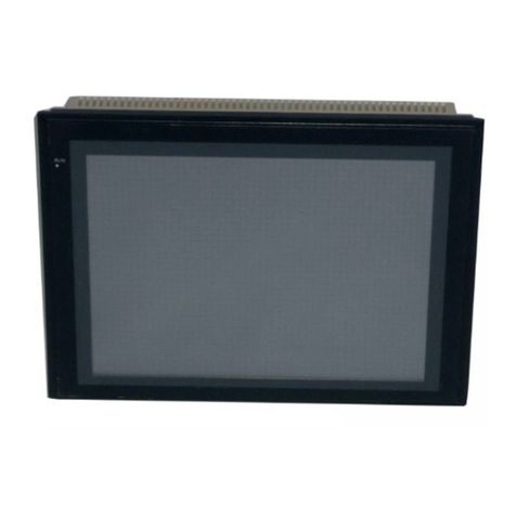
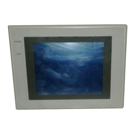
Omron NTXS User manual

Cat. No. V03E-EN-01 Note: Specifications subject to change without notice.
Programmable Terminals NTXS User´s ManualCat. No. V03E-EN-01
USER´S MANUAL
Programmable Terminals
NTXS
Cat. No. V03E-EN-02
Authorised Distributor:
Printed in Europe
V03E-_-01+NTXS+UsersManual.qxd 14.02.2005 09:26 Seite 1

i
Preliminary
Thank you for purchasing NTXS Series product from Omron. NTXS Series Products are versatile
operator interfaces with Microsoft Windows® based configuration Software.
This manual will help you to safely install, configure and operate NTXS Products.
All the safety warnings and precautions must be followed to ensure proper unit performance and per-
sonal safety.
Warnings used in this manual:
DANGER Danger Warnings are used to indicate situations, ocations
and conditions that can cause serious injury or death.
CAUTION Caution Warnings are used to indicate situations and conditions
that can cause operator injury and/or unit damage.
If additional information or technical assistance is needed please contact:
Omron Europe B.V.
Wegalaan 67-69
NL-2132 JD Hoofddorp
The Netherlands
Phone:(+31)23-5681300
Fax :(+31)23 5681388
URL:www.omron-industrial.com
ManualRevisions:
If you contact us in reference to this manual, please include the following document number:
Name: NTXS Manual
Document: V03E-EN-02
IMPORTANT
NTXS Series Products are intended to be operator interfaces, to work with PLCs which
actually take control actions. It is assumed that the user is well acquainted with the PLC
system being used. Never use NTXS units to perform emergency stop applications. It is
advised that separate switches be used outside the PLC forANY emergency stops.
Any mechanical or electrical modification to the units will
void all warranties.
!

ii
Contents
INTRODUCTION 1
1.1 Purpose of this manual 2
1.1.1 HMI Basics 2
1.1.2 Hardware Requirements 3
1.2 NTXS Overview 4
1.2.1 What is NTXS series HMI? 4
1.3 How NTXS Works 5
1.3.1 Specifications of NTXS Series 8
HARDWARE 19
2.1 Safety Precaution 20
2.2 Installation Instructions 20
2.3 Power Requirements 22
2.4 Wiring Diagram 23
2.5 Communication Ports 23
BEFORE YOU BEGIN 30
3.1 Connecting the HMI to your Computer 31
3.2 Starting NTXS Software 32
3.2.1 Installing NTXS Software 32
3.2.2 Steps for starting NTXS Software 34
3.2.3 Uninstalling NTXS Software 35
3.3 Setting Network Configuration 35
3.3.1 Setting Network Configuration For NT2S Series Products 36
3.3.2 Setting Network Configuration For NT3S Series Products 37
USING NTXS SOFTWARE 42
4.1 NTXS Menu Structure 43
4.1.1 File Menu 45
4.1.2 Define Menu 46
4.1.3 Communicate Menu 47
4.1.4 Utilities Menu 47
4.1.5 Help Menu 48
4.2 Creating New Application 48
4.3 Creating Screens 54
4.3.1 Protecting Application Using Password 55
4.4 Data Entry Object 55
4.5 Display Data Object 56
4.6 Global And Power On Task 56
4.7 Global Keys 58
4.8 Screen Keys 59
REPRESENTING DATA BY OBJECTS AND WIZARDS 60
5.1 Alphanumeric Objects 61
5.1.1 Text Objects 61
5.1.2 Data Entry Objects 61
5.1.3 Display Data 63

iii
5.1.4 Time 66
5.1.5 Date 66
5.2 Graphic Wizards 69
5.2.1 Line 69
5.2.2 Rectangle 70
5.2.3 Ellipse 70
5.2.4 Rounded Rectangle 71
5.2.5 Bargraph 71
5.2.6 Bitmap 72
5.3 Wizards 73
5.3.1 Bit Button 74
5.3.2 Word Button 78
5.3.3 Bit Lamp 81
5.3.4 Word Lamp 85
5.3.5 Multiple Bargraph 87
5.3.6 Analog Meter 93
5.3.7 Real Time Trend 98
5.3.8 Numeric Keypad 103
TASK MANAGEMENT 108
6.1 Application TaskList 109
6.2 Screen TaskList 111
6.3 Key Tasklist 113
6.3.1 For Keypad Products 113
6.3.2 For Touch screen Products 115
USING LANGUAGES 131
7.1 Export Functionality 132
7.2 Import Functionality 134
7.3 Language conversion utility 136
7.3.1 File Menu 136
7.3.2 Edit Menu 139
7.3.3 View Menu 139
7.3.4 Help Menu 139
7.4 Multi-Language Text Wizard 139
7.4.1 Configure Languages 140
7.4.2 Displaying Multiple Languages in Unit 143
UPLOADING AND DOWNLOADING FROM UNIT 144
8.1 Upload 145
8.2 Download 146
8.3 Error Catalog 147
ALARMS 149
9.1 Define Alarm 150
9.1.1 Alarm Definition 151
9.1.2 Alarm Object 152
PRINTING 154
10.1 Printing from NTXS unit 155
10.2 Printing from NTXS Software 156
MISCELLANEOUS 158

iv
11.1 Convert Application 159
11.2 Memory Configuration Wizard 160
11.3 Font Editor 161
11.4 Image Conversion to bmp 163
DIAGNOSTICS & MAINTENANCE 165
12.1 Diagnostics 166
12.1.1 Erase Keys 166
12.1.2 Touchscreen Calibration Loss 167
12.2 Maintenance 168
APPENDIX 169
A Omron Cable References and Diagrams 170
1 Omron Cable References for connection to PLC’s peripheral ports ........
(CMOS) 170
2 Omron Cable References for connection to PLC’s serial ports (RS232C) ...
170
3 Omron Cable References for Programming cable (PC to NTXS) 170
4 Omron Cable Diagrams for Serial cables 171
4.1 NT2S-CN232-V1 / NT2S-CN235-V1 171
4.2 NT2S-CN242-V1 172
5 Omron Cable Disgram for NT2S / NT3S Programming cable 173
5.1 NT2S-CN002 173
6 Omron Cable Diagram for RS422 Communication cable XtraDrive and.......
NT3S 174
B Non-Omron Cable Diagrams 175
1 AB MICROLOGIX SERIES TO NTXS UNIT 175
2 AB SLC DF1 PORT TO NTXS UNIT 176
3 AROMAT FP0 / FPM TO NTXS UNIT 177
4 AROMAT FP1 TO NTXS UNIT 178
5 AROMAT FP2 TO NTXS UNIT 179
6 CONTROL TECHNIQUES TO NTXS UNIT 180
7 DANFOSS DRIVE TO NTXS UNIT 181
8 GE90 SERIES PLC TO NTXS UNIT 182
9 GE90 SERIES SNP-X PLC TO NTXS UNIT 183
10 IDEC MICRO3 TO NTXS UNIT 184
11 IDEC MICROSMART PLC TO NTXS UNIT 185
12 KEYENCE KV PLC TO NTXS UNIT 186
13 KOYO DL205 PLC TO NTXS UNIT 187
14 LG MASTER K SERIES PLC TO NTXS UNIT 188
15 MITSUBISHI FX SERIES PLC TO NTXS UNIT 189
16 MITSUBISHI FX0 PLC TO NTXS UNIT 190
17 SIEMENS STEP 7 MICRO(S7-200) PLC TO NTXS UNIT 191
18 SIEMENS-S7 300 SERIES PLC TO NTXS UNIT 192
19 TOSHIBAT1 PLC TO NTXS UNIT 193
20 TOSHIBAT2 PLC TO NTXS UNIT 194
21 TOSHIBAT1 LINK PORT TO NTXS UNIT 195
22 TOSHIBAT2 LINK PORT TO NTXS UNIT 196
23 TOSHIBAINVERTER S SERIES TO NTXS UNIT 197
24 TSX(07/37/57) PLC TO NTXS UNIT 198
v
25 TWIDO PLC TO NTXS UNIT 199
C List Of Features 200
D List Of Supported Devices 203
E Technical Support 204
Index.................................................... 205

Introduction
1
INTRODUCTION
In this chapter. . . .
♦Purpose of this manual
HMI Basics
HardwareConfiguration
♦NTXS Overview
What is NTXS series HMI?
How NTXS works?
NTXS Series Specifications

Introduction
2
1.1 Purpose of this manual
Thank you for purchasing NTXS Series Products from Omron. NTXS Series Products are versatile
operator interfaces with Microsoft Windows based configuration Software. This manual explains the
operation of the NTXS Series and how to implement available features using the NTXS Software. This
manual will help you to install, configure and operate NTXS product.
1.1.1 HMI Basics
Operator Interface Terminals (HMIs) provide much more versatility than traditional mechanical control
panels.An HMI allows a plant floor operator to monitor current conditions of a control system and, if
necessary, to initiate a change in the operation of the system. HMIs connect to programmable logic
controllers (PLCs) typically through the serial communications port. The HMI can be programmed to
monitor and/or change current values stored in the data memory of the PLC.
HMIs can have either text-based or graphics-based displays.Atext-based HMI can display printable
text characters but can not print graphics.
The NTXS Series HMIs are available in both Text display based HMI and graphics display based HMIs.
What is a Project?
A project is a user created application in NTXS Software.A project contains information such as NTXS
model, Network Configuration, Screen information, Task information etc.
What is a Screen?
Ascreen is a visual representation of objects placed on the HMI screen.Any partially sized window is
usually referred to as a popup screen or window. User can create his customized screen according to
his requirements. Popup windows can also appear on the HMI display by pressing buttons on the
touch screen. Maximum number of screens in an application is limited by the application memory size.
A more in depth discussion on screen is covered in chapter 4.
What is an Object?
An object placed on HMI screen can perform actions such as displaying text messages, writing value to
PLC register, or displaying an alarm on HMI screen etc. An object can be classified as Text object and
Graphical object.
For example, a Text Object is used to display text on the HMI. But objects are also used to configure
the HMI to perform some action. For example, a Display Data Object tells the HMI to continuously
monitor a PLC register that is used by the PLC. Some objects can display a graphics shape on the
HMI screen and perform some action. ABit Button Object creates a graphic object on the HMI that
when pressed, activates a bit in the PLC.

Introduction
3
1.1.2 Hardware Requirements
The following basic PC hardware configuration is needed to configure and operate your NTXS
Software.
DEVICE MINIMUM REQUIREMENT
IBM Compatible PC with 266 MHz Pentium® II or higher Pentium
Pentium Processor compatible CPU
Operating System Windows® 2000 and above
System RAM At least 64 megabytes (MB) of RAM, more
memory generally improves responsiveness
Hard Disk 150 MB Free Memory Space
VGA Monitor Color 800 x 600 with 24 bit True Color
SettingResolution
Serial Port Serial Port for Downloading
Mouse Microsoft® Mouse or compatible pointing device
Keyboard Required
These are the minimum system requirements for running the NTXS application.

Introduction
4
1.2 NTXS Overview
1.2.1 What is NTXS series HMI?
NTXS Series operator interfaces provide Human-Machine Interface to the Programmable Logic
Controller. The HMIs communicate with PLCs using their serial communications ports.
Configuration of NTXS:
Each NTXS unit has to be configured using the NTXS Software before connecting it to the PLC.
NTXS-IBM
Normal Operation:
After configuration is completed, NTXS should be connected with a PLC to start the system.
PLC To PLC
Programming Port
PLC port
of unit
Connecting
Cable
PLC1 PLC2

Introduction
5
1.3 How NTXS Works
The NTXS follows a specific sequence for performing the tasks defined by the user in the application.
The sequence is as shown below
Power-up
Message
Power up Task
START
IBM
Comm
?
A
Complete IBM
Communication
PLC
Comm
Error
?
Y
N
N
YRe-establish PLC
Communication
Re-Start
Global Task
Check Screen
Number
N
Y
Same
Screen
Number
?
C
Perform After Hiding
Task for Previous
Screen
Password
Protected
Screen
?
N
Y
D
B

Introduction
6
Check if same key
pressed
Upload Alarm Block
Serv Alarm
Display Screen
Display Associated Screens
Serv While Showing Task
Y
N
Key Release task
Same
key
Pressed
?
Load new
keys
I
Valid
Screen
password
?
N
Y
Perform Before
Showing Task List
for new Screen
F
D
C
Upload Tag Block
B

Introduction
7
Y
N
New
key
Pressed
?
A
I
Y
N
Valid Key
Password
? A
Serv Key
Press Task
Password
Protected
Key ?
Y
G
N
G
A

Introduction
8
1.3.1 Specifications of NTXS Series
Models included in the NTXS series are as follows:
NT2S-SF121B-EV2
NT2S-SF122B-EV2
NT2S-SF123B-EV2
NT2S-SF125B-E
NT2S-SF126B-E
NT2S-SF127B-E
NT3S-ST121B-E
NT3S-ST123B-E
NT3S-ST124B-E
NT3S-ST126B-E

Introduction
9
NT2S-SF121B-EV2
System Components:
- Unit with LCD display, Membrane keypad and RTC.
- Power Supply connector.
- Installation Kit: Gasket, Two Mounting clamps
Note: User should order cables separately
Power Supply 24VDC
Voltage Rating 24 VDC + 10%
Power Rating 1.5W
Approvals CE, CSA and cULus Class 1
Div.2 Certified
Bezel IP65 Rated Keypad
Keypad Membrane Keypad With Tactile
Feedback Keys
Number Of Keys 6 user Definable keys
Memory
Total Memory 63KB
Application Memory 24KB
Data Register 1000
Retentive Register 1000
Display LCD Text Display
Display Type 2 lines of 16 characters Backlit LCD
LEDs 2 LEDs
Communication
Number of Ports 2
Type One RS232/CMOS port for
connecting to PLC and one RS232
port for programming and printing
PREV CLR
F1F2F3F4F5F 6
NEXT
Miscellaneous
Dimension 92.00 X 45.00 mm
Battery Coin Type, 3V Lithium
Battery 614-CR1225FH
Battery Backup 8 years typical battery
backup for RTC and
System data
Operating Temperature 0 0C to 50 0C
Storage Temperature -25 0C to 80 0C
Mounting Method Panel Mounting
Clock(RTC) Real Time Clock
Function(Date & Time)
Humidity 10% To 90%
(Noncondensing)
Immunity to ESD Level 3 as per IEC1000-4-2
Immunity to Transients Level 3 as per IEC1000-4-4
Immunity to Radiated Level 3 as per IEC1000-4-3
RF
Emission EN55011 CISPRA

Introduction
10
NT2S-SF122B-EV2
System Components:
- Unit with LCD display, Membrane keypad
- Installation Kit: Gasket, Two Mounting clamps
Note: User should order cables separately
Power Supply 5VDC
Voltage Rating 5 VDC + 10% from PLC
Approvals CE, CSA and cULus Class 1
Div.2 Certified
Bezel IP65 Rated Keypad
Keypad Membrane Keypad With Tactile
Feedback Keys
Number Of Keys 6 user Definable keys
Memory
Total Memory 63KB
Application Memory 24KB
Data Register 1000
Retentive Register 1000
Display LCD Text Display
Display Type 2 lines of 16 characters
Backlit LCD
LEDs 2 LEDs
Communication
Number of Ports 2
Type One RS232/CMOS port for
connecting to PLC and one RS232
port for programming and printing
PREV CLR
F1F2F3F4F5F 6
NEXT
Miscellaneous
Dimension 92.00 X 45.00 mm
Operating Temperature 0 0C to 50 0C
Storage Temperature -25 0C to 80 0C
Mounting Method Panel Mounting
Humidity 10% To 90%
(Noncondensing)
Immunity to ESD Level 3 as per IEC1000-4-2
Immunity to Transients Level 3 as per IEC1000-4-4
Immunity to Radiated Level 3 as per IEC1000-4-3
RF
Emission EN55011 CISPRA

Introduction
11
NT2S-SF123B-EV2
System Components:
- Unit with LCD display, Membrane keypad
- Installation Kit: Gasket, Two Mounting clamps
Note: User should order cables separately
Power Supply 5VDC
Voltage Rating 5 VDC + 10% from PLC
Approvals CE, CSA and cULus Class 1
Div.2 Certified
Bezel IP65 Rated Keypad
Keypad Membrane Keypad With Tactile
Feedback Keys
Number Of Keys 6 keys
Display LCD Text Display
Display Type 2 lines of 16 characters
Backlit LCD
LEDs 2 LEDs
Communication
Number of Ports 1
Type CMOS port for communication
to PLC
DATA CLR
F 1 F2F3F4F5F 6
REG
Miscellaneous
Dimension 92.00 X 45.00 mm
Operating Temperature 0 0C to 50 0C
Storage Temperature -25 0C to 80 0C
Mounting Method Panel Mounting
Humidity 10% To 90%
(Noncondensing)
Immunity to ESD Level 3 as per IEC1000-4-2
Immunity to Transients Level 3 as per IEC1000-4-4
Immunity to Radiated Level 3 as per IEC1000-4-3
RF
Emission EN55011 CISPRA

Introduction
12
NT2S-SF125B-E
System Components:
- Unit with LCD display, Membrane keypad and RTC.
- Power Supply connector.
- Installation Kit: Gasket, Two Mounting clamps
Note: User should order cables separately
Communication
Number of Ports 2
Type One RS232/CMOS port for
connecting to PLC and one
RS232 port for Programming
and Printing
Power Supply 24VDC
Voltage Rating 24 VDC + 10%
Power Rating 1.5W
Approvals CE and cULus Class1 Div. 2
Certified
Bezel IP65 Rated Keypad
Keypad PCB based Keypad With
Tactile Feedback Keys
Number Of Keys 20 keys
Memory
Total Memory 63KB
Application Memory 24KB
Data Register 1000
Retentive Register 1000
Display LCD Text Display
Display Type 2 lines of 16 characters
Backlit LCD
1
4
7
CLR
2
5
8
0
3
6
9
+/-
F1
F2
F3
F4
F5
F6
F7
F8
Miscellaneous
Dimension 92.00 X 92.00 mm
Battery Coin Type, 3V Lithium Battery
614-CR1225FH
Battery Backup 8 years typical battery backup
for RTC and System data
Operating Temperature 0 0C to 50 0C
Storage Temperature -25 0C to 80 0C
Mounting Method Panel Mounting
Clock(RTC) Real Time Clock Function
(Date & Time)
Humidity 10% To 90%
(Noncondensing)
Immunity to ESD Level 3 as per IEC1000-4-2
Immunity to Transients Level 3 as per IEC1000-4-4
Immunity to Radiated Level 3 as per IEC1000-4-3
RF
Emission EN55011 CISPRA

Introduction
13
NT2S-SF126B-E
System Components:
- Unit with LCD display, Membrane keypad
- Installation Kit: Gasket, Two Mounting clamps
Note: User should order cables separately
Communication
Number of Ports 2
Type One RS232/CMOS port for
connecting to PLC and one
RS232 port for Programming
and Printing
Power Supply 5VDC
Voltage Rating 5 VDC + 10% from PLC
Approvals CE and cULus Class1 Div. 2
Certified
Bezel IP65 Rated Keypad
Keypad PCB based Keypad With
Tactile Feedback Keys
Number Of Keys 20 User definable keys
Memory
Total Memory 63KB
Application Memory 24KB
Data Register 1000
Retentive Register 1000
Display LCD Text Display
Display Type 2 lines of 16 characters
Backlit LCD
1
4
7
CLR
2
5
8
0
3
6
9
+/-
F1
F2
F3
F4
F5
F6
F7
F8
Miscellaneous
Dimension 92.00 X 92.00 mm
Operating Temperature 0 0C to 50 0C
Storage Temperature -25 0C to 80 0C
Mounting Method Panel Mounting
Clock(RTC) Does not support RTC
Humidity 10% To 90% (Noncondensing)
Immunity to ESD Level 3 as per IEC1000-4-2
Immunity to Transients Level 3 as per IEC1000-4-4
Immunity to Radiated Level 3 as per IEC1000-4-3
RF
Emission EN55011 CISPRA

Introduction
14
NT2S-SF127B-E
System Components:
- Unit with LCD display, Membrane keypad
- Installation Kit: Gasket, Two Mounting clamps
Note: User should order cables separately
Power Supply 5VDC
Voltage Rating 5 VDC + 10% from PLC
Approvals CE and cULus Class1 Div.2
Certified
Bezel IP65 Rated Keypad
Keypad PCB based Keypad With
Tactile Feedback Keys
Number Of Keys 20 keys
Display LCD Text Display
Display Type 2 lines of 16 characters
Backlit LCD
Communication
Number of Ports 1
Type CMOS port for connecting
to PLC
1
4
7
CLR
2
5
8
0
3
6
9
+/-
F1
F2
F3
F4
REG
DATA
Miscellaneous
Dimension 92.00 X 92.00 mm
Operating Temperature 0 0C to 50 0C
Storage Temperature -25 0C to 80 0C
Mounting Method Panel Mounting
Clock(RTC) Does not support RTC
Humidity 10% To 90% (Noncondensing)
Immunity to ESD Level 3 as per IEC1000-4-2
Immunity to Transients Level 3 as per IEC1000-4-4
Immunity to Radiated Level 3 as per IEC1000-4-3
RF
Emission EN55011 CISPRA
This manual suits for next models
11
Table of contents
Other Omron Touch Terminal manuals

Omron
Omron NV3W Series Instruction manual

Omron
Omron NS - Owner's manual

Omron
Omron NT-series User manual

Omron
Omron NS10-TV Series User manual

Omron
Omron DRT1-ID User manual

Omron
Omron NT620C User manual

Omron
Omron NS7 Series User guide

Omron
Omron NP Series User manual

Omron
Omron NA-series User guide

Omron
Omron NT21 User manual

Omron
Omron NV Series User guide

Omron
Omron NS8-TV0-V2 User guide

Omron
Omron NT11 - 01-2004 User manual

Omron
Omron WT30 User manual

Omron
Omron Sysmac NA Series User manual

Omron
Omron NS - User guide

Omron
Omron NS-CXDC1-V1 User manual

Omron
Omron NT631 Series User manual

Omron
Omron NA-series Instructions for use

Omron
Omron NT600M Series User manual