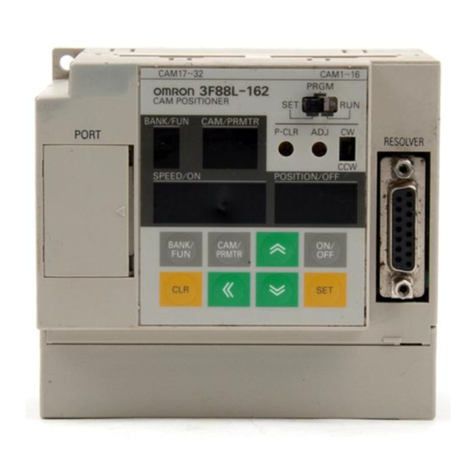
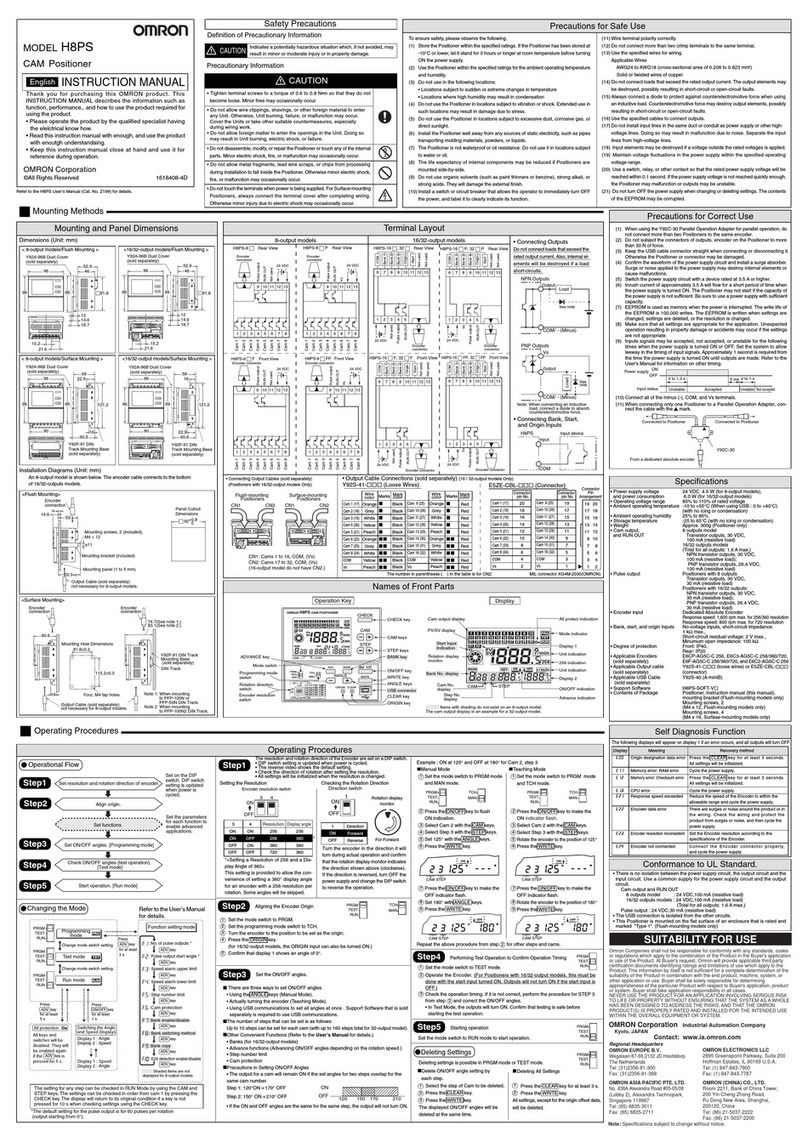
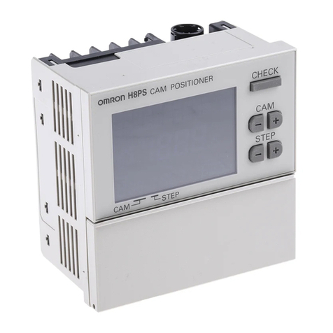
Omron 3F88L-160 User manual

USER’S MANUAL
3F88L-160/162 Cam Positioner
Cat. No. O008-E1-04

Thank you for choosing this 3F88L-160/162 Cam Positioner. Proper use and handling of
the product will ensure proper product performance, will lengthen product life, and may
prevent possible accidents.
Please read this manual thoroughly and handle and operate the product with care.
1. To ensure safe and proper use of the OMRON Cam Positioners, please read this USER’S
MANUAL (Cat. No. O008-E1) to gain sufficient knowledge of the devices, safety information,
and precautions before actual use.
2. The products are illustrated without covers and shieldings for closer look in this USER’S
MANUAL. For actual use of the products, make sure to use the covers and shieldings as speci-
fied.
3. This USER’S MANUAL and other related user’s manuals are to be delivered to the actual end
users of the products.
4. Please keep this manual close at hand for future reference.
5. If the product has been left unused for a long time, please inquire at our sales representative.
NOTICE
1. This manual describes the functions of the product and relations with other products. You
should assume that anything not described in this manual is not possible.
2. Although care has been given in documenting the product, please contact your OMRON
representative if you have any suggestions on improving this manual.
3. The product contains potentially dangerous parts under the cover. Do not attempt to open
the cover under any circumstances. Doing so may result in injury or death and may damage
the product. Never attempt to repair or disassemble the product.
4. We recommend that you add the following precautions to any instruction manuals you pre-
pare for the system into which the product is being installed.
SPrecautions on the dangers of high-voltage equipment.
SPrecautions on touching the terminals of the product even after power has been turned off. (These
terminals are live even with the power turned off.)
5. Specifications and functions may be changed without notice in order to improve product
performance.
Items to Check Before Unpacking
1. Check the following items before removing the 3F88L-160/162 Cam Positioner from the
package:
SHas the correct product been delivered (i.e., the correct model number and specifications)?
SHas the product been damaged in shipping?
SAre any screws or bolts loose?
SHave all accessories been correctly delivered together with or attached to the product? The acces-
sory for the 3F88L-160/162 Cam Positioner is the Safety Precautions only.
Mounting screws and other necessary parts must be provided by the customer. Should there
be any problems with this product, contact your nearest OMRON sales representative.
2. Check the following items before removing the 3F88L-RS17/17T/15/15W Resolver from
the package:
SHas the correct product been delivered (i.e., the correct model number and specifications)?
SHas the product been damaged in shipping?
SAre any screws or bolts loose?
SHave all accessories been correctly delivered together with or attached to the product? The acces-
sories for the 3F88L-RS17/17T are one 3F88L-RL10 Coupling and one copy of the user’s manual.
The accessories for the 3F88L-RS15/15W are one 3F88L-RL6 Coupling and three mounting claws.
Should there be any problems with this product, contact your nearest OMRON sales repre-
sentative.

!
!
!
Notice:
OMRON products are manufactured for use according to proper procedures by a qualified
operator and only for the purposes described in this manual.
The following conventions are used to indicate and classify precautions in this manual. Al-
ways heed the information provided with them. Failure to heed precautions can result in inju-
ry to people or damage to property.
DANGER Indicates an imminently hazardous situation which, if not avoided, will result in death
or serious injury. Additionally, there may be severe property damage.
WARNING Indicates a potentially hazardous situation which, if not avoided, could result in death
or serious injury. Additionally, there may be severe property damage.
Caution Indicates a potentially hazardous situation which, if not avoided, may result in minor
or moderate injury, or property damage.
OMRON Product References
All OMRON products are capitalized in this manual. The word “Unit” is also capitalized when
it refers to an OMRON product, regardless of whether or not it appears in the proper name
of the product.
The abbreviation “Ch,” which appears in some displays and on some OMRON products, of-
ten means “word” and is abbreviated “Wd” in documentation in this sense.
The abbreviation “PC” means Programmable Controller and is not used as an abbreviation
for anything else.
Visual Aids
The following headings appear in the left column of the manual to help you locate different
types of information.
Note Indicates information of particular interest for efficient and convenient operation of the product.
OMRON, 1999
All rights reserved. No part of this publication may be reproduced, stored in a retrieval system, or transmitted,
in any form, or by any means, mechanical, electronic, photocopying, recording, or otherwise, without the prior
written permission of OMRON.
No patent liability is assumed with respect to the use of the information contained herein. Moreover, because
OMRON is constantly striving to improve its high-quality products, the information contained in this manual
is subject to change without notice. Every precaution has been taken in the preparation of this manual. Never-
theless, OMRON assumes no responsibility for errors or omissions. Neither is any liability assumed for dam-
ages resulting from the use of the information contained in this publication.

!
!
!
!
Intended Audience
This manual is intended for the following personnel, who must also have knowledge of electrical sys-
tems (an electrical engineer or the equivalent).
SPersonnel in charge of installing FA systems.
SPersonnel in charge of designing FA systems.
SPersonnel in charge of managing FA systems and facilities.
General Precautions
The user must operate the product according to the performance specifications described in the op-
eration manuals.
Before using the product under conditions which are not described in the manual or applying the
product to nuclear control systems, railroad systems, aviation systems, vehicles, combustion sys-
tems, medical equipment, amusement machines, safety equipment, and other systems, machines,
and equipment that may have a serious influence on lives and property if used improperly, consult
your OMRON representative.
Make sure that the ratings and performance characteristics of the product are sufficient for the sys-
tems, machines, and equipment, and be sure to provide the systems, machines, and equipment with
double safety mechanisms.
This manual provides information for programming and operating the Unit. Be sure to read this manu-
al before attempting to use the Unit and keep this manual close at hand for reference during opera-
tion.
WARNING It is extremely important that a PC and all PC Units be used for the specified purpose
and under the specified conditions, especially in applications that can directly or
indirectly affect human life. You must consult with your OMRON representative
before applying a PC System to the above-mentioned applications.
Safety Precautions
General Warnings
WARNING Do not attempt to disassemble the Unit while power is being supplied. Doing so may
result in electrical shock.
WARNING Do not touch any of the terminals while power is being supplied. Doing so may result
in electrical shock.
WARNING Take safety measures outside the Cam Positioner to ensure safety for the entire
system in the event of Cam Positioner failure or error caused by external factors of
the Cam Positioner.
Faulty operations may result in serious accidents.
SEmergency stop circuits, interlock circuits, limit circuits, and similar safety mea-
sures must be included in control circuits outside the Cam Positioner.
SThe Cam Positioner turns OFF all outputs when its self-diagnostic function detects
an error (ERROR is OFF), when TRIG input turns ON, or when RESET input turns
ON. Take safety measures outside the Cam Positioner to ensure safety for the en-
tire system in such an event.
SThe Cam Positioner output may remain ON or OFF due to damage to an output
transistor or for some other reason. Take safety measures outside the Cam Posi-
tioner to ensure safety for the entire system in such an event.

!
!
!
!
!
!
!
!
!
!
!
!
!
!
!
!
General Precautions
Caution Fail-safe measures must be taken by the customer to ensure safety in the event of
incorrect, missing, or abnormal signals caused by broken signal lines, momentary
power interruptions, or other causes.
Caution Always use the power supply voltages specified in the operation manuals.
Caution Take appropriate measures to ensure that the specified power with the rated voltage
and frequency is supplied. Be particularly careful in locations where the power sup-
ply is unstable.
Caution Install external breakers and take other safety measures against short-circuiting in
external wiring.
Caution Disconnect the functional ground terminal from the protective ground terminal when
performing insulation resistance or withstand voltage tests
Caution Always connect to a ground of 100 Ωor less when installing the Unit.
Caution Do not attempt to disassemble, repair, or modify the Unit.
Caution Leave the label attached to the Unit when wiring.
Caution Remove the label after the completion of wiring to ensure proper heat dissipation.
Caution Use crimp terminals for wiring. Do not connect bare stranded wires directly to termi-
nals.
Caution Thoroughly check all wiring before turning ON the power supply.
Caution Wire all connections correctly.
Caution Do not place objects on top of the cables or other wiring lines.
Caution Do not pull on the cables or bend the cables beyond their natural limit.
Caution Before touching a Unit, be sure to first touch a grounded metallic object in order to
discharge any static built-up.
Caution Be sure that all the mounting screws, terminal screws, and cable connector screws
are tightened to the torque specified in the operation manual. For DIN track mount-
ing, push the Cam Positioner forward until the lock snaps into place.

!
!
!
!
!
!
!
!
!
!
Caution Be sure that cables and other items with locking devices are properly locked into
place.
Caution Always turn OFF the power supply to the Unit before attempting any of the following.
SAssembling the Unit.
SSetting switches.
SConnecting cables or wiring the system.
SConnecting or disconnecting the connectors.
Caution Thoroughly check the newly created cam programs, parameter settings, and switch
settings for proper execution before actually running them.
Caution Confirm that no adverse effect will occur in the system before attempting any of the
following.
SSwitching the operating mode of the Unit
SOrigin compensation
SSwitching the execution bank
Caution When installing the Unit, adjust the origin before starting operation.
Caution Be sure that the number of resolver rotations is always within the allowable range.
Caution When replacing the Unit, transfer all the parameters and cam programs from the old
Unit to the new Unit before restarting operation.
Caution Do not apply voltages to the input terminal in excess of the rated input voltage.
Caution Do not apply voltages or connect loads to the output terminal or cam output connec-
tor in excess of the maximum switching capacity.
Caution Do not touch the terminals for one minute after the power is turned OFF.

!
!
!
Installation Precautions
Caution Install the Unit properly as specified in the operation manual.
Caution Do not install the Unit in the following locations.
SLocations subject to direct sunlight.
SLocations subject to temperatures or humidity outside the range specified in the
specifications.
SLocations subject to condensation as the result of severe changes in temperature.
SLocations subject to corrosive or flammable gases.
SLocations subject to dust (especially iron dust) or salts.
SLocations subject to exposure to water, oil, or chemicals.
SLocations subject to shock or vibration.
Caution Take appropriate and sufficient countermeasures when installing the Unit in the fol-
lowing locations.
SLocations subject to static electricity or other forms of noise.
SLocations subject to strong electromagnetic fields and magnetic fields.
SLocations subject to possible exposure to radioactivity.
SLocations close to power supplies.
Conformance to EC Directives
HApplicable Directives
SEMC Directives
SLow Voltage Directive
Concepts
EMC Directives
EMC Directives stipulate that the system must comply with both EMS and EMI standards
(see the following note). Because OMRON devices are designed for installation in various
equipment or machines, they comply with the relevant EMC standards so that the equip-
ment or machines can easily comply with the EMC standards. However, the systems used
by customers are diverse, and EMC-related performance of the OMRON devices that com-
ply with EC Directives will vary depending on the configuration, wiring, and other conditions
of the equipment or control panel in which the OMRON devices are installed. The customer
must, therefore, perform final checks to confirm that devices and the overall machine con-
form to EMC standards.
Note Applicable EMC (Electromagnetic Compatibility) standards are as follows:
EMS (Electromagnetic Susceptibility): EN61131-2
EMI (Electromagnetic Interference): EN61000-6-4
(Radiated emission: 10-m regulations)
Low Voltage Directive
Always ensure that devices operating at voltages of 50 to 1,000 V AC or 75 to 1,500 V DC
meet the required safety standards (EN61131-2).

Conformance to EC Directives
The 3F88L-160/162 Cam Positioner complies with EC Directives. To ensure that the system in which
the 3F88L-160/162 is installed complies with EC Directives, the following precautions must be ob-
served.
1. The 3F88L-160/162 is defined as an in-panel device according to the Low-voltage Directive.
The 3F88L-160/162 must, therefore, be installed within a control panel.
2. Reinforced insulation or double insulation must be used for the DC power supplies used as
I/O power supplies.
3. The 3F88L-160/162 conforms to the Common Emission Standard (EN61000-6-4) in rela-
tion to EMI. However, the radiated emission (10-m regulations) may vary depending on the
configuration of the control panel, connected devices, wiring, and other conditions. The user
must, therefore, confirm that devices and the overall machinery conform to EC Directives.

Terms and Conditions Agreement
Warranty, Limitations of Liability
Warranties
Exclusive
Warranty
Omron’s exclusive warranty is that the Products will be free from defects in materials
and workmanship for a period of twelve months from the date of sale by Omron (or
such other period expressed in writing by Omron). Omron disclaims all other war-
ranties, express or implied.
Limitations OMRON MAKES NO WARRANTY OR REPRESENTATION, EXPRESS OR
IMPLIED, ABOUT NON-INFRINGEMENT, MERCHANTABILITY OR FITNESS FOR
A PARTICULAR PURPOSE OF THE PRODUCTS. BUYER ACKNOWLEDGES
THAT IT ALONE HAS DETERMINED THAT THE PRODUCTS WILL SUITABLY
MEET THE REQUIREMENTS OF THEIR INTENDED USE.
Omron further disclaims all warranties and responsibility of any type for claims or
expenses based on infringement by the Products or otherwise of any intellectual
property right.
Buyer Remedy Omron’s sole obligation hereunder shall be, at Omron’s election, to (i) replace (in the
form originally shipped with Buyer responsible for labor charges for removal or
replacement thereof) the non-complying Product, (ii) repair the non-complying Prod-
uct, or (iii) repay or credit Buyer an amount equal to the purchase price of the non-
complying Product; provided that in no event shall Omron be responsible for war-
ranty, repair, indemnity or any other claims or expenses regarding the Products
unless Omron’s analysis confirms that the Products were properly handled, stored,
installed and maintained and not subject to contamination, abuse, misuse or inap-
propriate modification. Return of any Products by Buyer must be approved in writing
by Omron before shipment. Omron Companies shall not be liable for the suitability
or unsuitability or the results from the use of Products in combination with any elec-
trical or electronic components, circuits, system assemblies or any other materials
or substances or environments. Any advice, recommendations or information given
orally or in writing, are not to be construed as an amendment or addition to the
above warranty.
See http://www.omron.com/global/ or contact your Omron representative for pub-
lished information.
Limitation on
Liability; Etc
OMRON COMPANIES SHALL NOT BE LIABLE FOR SPECIAL, INDIRECT, INCI-
DENTAL, OR CONSEQUENTIAL DAMAGES, LOSS OF PROFITS OR PRODUC-
TION OR COMMERCIAL LOSS IN ANY WAY CONNECTED WITH THE
PRODUCTS, WHETHER SUCH CLAIM IS BASED IN CONTRACT, WARRANTY,
NEGLIGENCE OR STRICT LIABILITY.
Further, in no event shall liability of Omron Companies exceed the individual price of
the Product on which liability is asserted.

Application Considerations
Suitability of
Use
Omron Companies shall not be responsible for conformity with any standards,
codes or regulations which apply to the combination of the Product in the Buyer’s
application or use of the Product. At Buyer’s request, Omron will provide applicable
third party certification documents identifying ratings and limitations of use which
apply to the Product. This information by itself is not sufficient for a complete deter-
mination of the suitability of the Product in combination with the end product,
machine, system, or other application or use. Buyer shall be solely responsible for
determining appropriateness of the particular Product with respect to Buyer’s appli-
cation, product or system. Buyer shall take application responsibility in all cases.
NEVER USE THE PRODUCT FOR AN APPLICATION INVOLVING SERIOUS RISK
TO LIFE OR PROPERTY WITHOUT ENSURING THAT THE SYSTEM AS A
WHOLE HAS BEEN DESIGNED TO ADDRESS THE RISKS, AND THAT THE
OMRON PRODUCT(S) IS PROPERLY RATED AND INSTALLED FOR THE
INTENDED USE WITHIN THE OVERALL EQUIPMENT OR SYSTEM.
Programmable
Products
Omron Companies shall not be responsible for the user’s programming of a pro-
grammable Product, or any consequence thereof.
Disclaimers
Performance
Data
Data presented in Omron Company websites, catalogs and other materials is pro-
vided as a guide for the user in determining suitability and does not constitute a war-
ranty. It may represent the result of Omron’s test conditions, and the user must
correlate it to actual application requirements. Actual performance is subject to the
Omron’s Warranty and Limitations of Liability.
Change in
Specifications
Product specifications and accessories may be changed at any time based on
improvements and other reasons. It is our practice to change part numbers when
published ratings or features are changed, or when significant construction changes
are made. However, some specifications of the Product may be changed without
any notice. When in doubt, special part numbers may be assigned to fix or establish
key specifications for your application. Please consult with your Omron’s represen-
tative at any time to confirm actual specifications of purchased Product.
Errors and
Omissions
Information presented by Omron Companies has been checked and is believed to
be accurate; however, no responsibility is assumed for clerical, typographical or
proofreading errors or omissions.

USER’S MANUAL
3F88L-160/162 Cam Positioner

Table of Contents
Chapter 1. Outline 1-1. . . . . . . . . . . . . . . . . . . . . . . . . . . . . . . . . . . . . . . . . .
1-1 Functions 1-2. . . . . . . . . . . . . . . . . . . . . . . . . . . . . . . . . . . . . . . . . . . . . . . . . . . . . . . . . . . . . . . . . .
1-1-1 Basic Operation 1-2. . . . . . . . . . . . . . . . . . . . . . . . . . . . . . . . . . . . . . . . . . . . . . . . . . . . . . .
1-1-2 Resolution 1-2. . . . . . . . . . . . . . . . . . . . . . . . . . . . . . . . . . . . . . . . . . . . . . . . . . . . . . . . . . .
1-1-3 Modes 1-3. . . . . . . . . . . . . . . . . . . . . . . . . . . . . . . . . . . . . . . . . . . . . . . . . . . . . . . . . . . . . .
1-1-4 Selecting the Function Level 1-3. . . . . . . . . . . . . . . . . . . . . . . . . . . . . . . . . . . . . . . . . . . .
1-1-5 Basic Functions 1-3. . . . . . . . . . . . . . . . . . . . . . . . . . . . . . . . . . . . . . . . . . . . . . . . . . . . . . .
1-1-6 Initial Settings Functions 1-4. . . . . . . . . . . . . . . . . . . . . . . . . . . . . . . . . . . . . . . . . . . . . . .
1-1-7 Applied Functions 1-4. . . . . . . . . . . . . . . . . . . . . . . . . . . . . . . . . . . . . . . . . . . . . . . . . . . . .
1-2 System Configuration 1-6. . . . . . . . . . . . . . . . . . . . . . . . . . . . . . . . . . . . . . . . . . . . . . . . . . . . . . . .
1-3 Name and Function of Each Part 1-7. . . . . . . . . . . . . . . . . . . . . . . . . . . . . . . . . . . . . . . . . . . . . . . .
1-3-1 Display Section 1-8. . . . . . . . . . . . . . . . . . . . . . . . . . . . . . . . . . . . . . . . . . . . . . . . . . . . . . .
1-3-2 Switches 1-8. . . . . . . . . . . . . . . . . . . . . . . . . . . . . . . . . . . . . . . . . . . . . . . . . . . . . . . . . . . .
1-3-3 Operation Keys 1-9. . . . . . . . . . . . . . . . . . . . . . . . . . . . . . . . . . . . . . . . . . . . . . . . . . . . . . .
1-3-4 Terminal Block and Connectors 1-9. . . . . . . . . . . . . . . . . . . . . . . . . . . . . . . . . . . . . . . . . .
1-4 Glossary 1-10................................................................. . .
1-5 Operation Procedure 1-11. . . . . . . . . . . . . . . . . . . . . . . . . . . . . . . . . . . . . . . . . . . . . . . . . . . . . . . . .
1-5-1 Before Operation 1-11. . . . . . . . . . . . . . . . . . . . . . . . . . . . . . . . . . . . . . . . . . . . . . . . . . . . . .
Chapter 2. Design 2-1. . . . . . . . . . . . . . . . . . . . . . . . . . . . . . . . . . . . . . . . . .
2-1 System Design 2-2. . . . . . . . . . . . . . . . . . . . . . . . . . . . . . . . . . . . . . . . . . . . . . . . . . . . . . . . . . . . . .
2-1-1 Selecting the Resolver 2-2. . . . . . . . . . . . . . . . . . . . . . . . . . . . . . . . . . . . . . . . . . . . . . . . .
2-1-2 Selecting the Output Device 2-4. . . . . . . . . . . . . . . . . . . . . . . . . . . . . . . . . . . . . . . . . . . . .
2-2 Installation 2-6.................................................................
2-2-1 External Dimensions 2-6. . . . . . . . . . . . . . . . . . . . . . . . . . . . . . . . . . . . . . . . . . . . . . . . . . .
2-2-2 Installation Environment 2-8. . . . . . . . . . . . . . . . . . . . . . . . . . . . . . . . . . . . . . . . . . . . . . .
2-2-3 Mounting the Resolver 2-9. . . . . . . . . . . . . . . . . . . . . . . . . . . . . . . . . . . . . . . . . . . . . . . . .
2-3 Wiring 2-13................................................................. . . .
2-3-1 System Connection Diagram 2-13. . . . . . . . . . . . . . . . . . . . . . . . . . . . . . . . . . . . . . . . . . . .
2-3-2 Standard Wiring Method 2-14. . . . . . . . . . . . . . . . . . . . . . . . . . . . . . . . . . . . . . . . . . . . . . . .
2-3-3 Terminal Block Wiring 2-16. . . . . . . . . . . . . . . . . . . . . . . . . . . . . . . . . . . . . . . . . . . . . . . . .
2-3-4 Resolver Wiring 2-21. . . . . . . . . . . . . . . . . . . . . . . . . . . . . . . . . . . . . . . . . . . . . . . . . . . . . .
2-3-5 Cam Output Wiring 2-22. . . . . . . . . . . . . . . . . . . . . . . . . . . . . . . . . . . . . . . . . . . . . . . . . . . .
2-3-6 Connecting a Display Unit 2-25. . . . . . . . . . . . . . . . . . . . . . . . . . . . . . . . . . . . . . . . . . . . . .
Chapter 3. Operation 3-1. . . . . . . . . . . . . . . . . . . . . . . . . . . . . . . . . . . . . . .
3-1 Nomenclature of Display and Operation Sections 3-2. . . . . . . . . . . . . . . . . . . . . . . . . . . . . . . . . .
3-2 Modes, Functions, and Display 3-4. . . . . . . . . . . . . . . . . . . . . . . . . . . . . . . . . . . . . . . . . . . . . . . . .
3-3 Operation Procedure 3-12. . . . . . . . . . . . . . . . . . . . . . . . . . . . . . . . . . . . . . . . . . . . . . . . . . . . . . . . .
3-3-1 Before Operation 3-12. . . . . . . . . . . . . . . . . . . . . . . . . . . . . . . . . . . . . . . . . . . . . . . . . . . . . .
3-4 Selecting Function Levels 3-14. . . . . . . . . . . . . . . . . . . . . . . . . . . . . . . . . . . . . . . . . . . . . . . . . . . . .
3-5 Basic Operation 3-20. . . . . . . . . . . . . . . . . . . . . . . . . . . . . . . . . . . . . . . . . . . . . . . . . . . . . . . . . . . . .
3-5-1 Function Level Selection Setting (SET Mode) 3-20. . . . . . . . . . . . . . . . . . . . . . . . . . . . . .
3-5-2 Initial Settings 3-21. . . . . . . . . . . . . . . . . . . . . . . . . . . . . . . . . . . . . . . . . . . . . . . . . . . . . . . .
3-5-3 Cam Program Creating and Checking (PRGM Mode/SET Mode) 3-24. . . . . . . . . . . . . . .
3-5-4 Resolver and Machinery Connection 3-37. . . . . . . . . . . . . . . . . . . . . . . . . . . . . . . . . . . . . .
3-5-5 Origin Compensation 3-37. . . . . . . . . . . . . . . . . . . . . . . . . . . . . . . . . . . . . . . . . . . . . . . . . .
3-5-6 Start Operation (RUN Mode) 3-38. . . . . . . . . . . . . . . . . . . . . . . . . . . . . . . . . . . . . . . . . . . .
3-5-7 I/O Monitor Function (RUN Mode) 3-40. . . . . . . . . . . . . . . . . . . . . . . . . . . . . . . . . . . . . . .
3-5-8 Control I/O Signals 3-42. . . . . . . . . . . . . . . . . . . . . . . . . . . . . . . . . . . . . . . . . . . . . . . . . . . .

Table of Contents
3-6 Applied Functions 3-44. . . . . . . . . . . . . . . . . . . . . . . . . . . . . . . . . . . . . . . . . . . . . . . . . . . . . . . . . . .
3-6-1 Function Level Selection Setting (SET Mode) 3-44. . . . . . . . . . . . . . . . . . . . . . . . . . . . . .
3-6-2 Parameter List (SET Mode) 3-45. . . . . . . . . . . . . . . . . . . . . . . . . . . . . . . . . . . . . . . . . . . . .
3-6-3 Parameter Explanation and Operation 3-49. . . . . . . . . . . . . . . . . . . . . . . . . . . . . . . . . . . . .
3-6-4 Origin Compensation and Origin Shift 3-56. . . . . . . . . . . . . . . . . . . . . . . . . . . . . . . . . . . . .
3-6-5 Backlash Compensation 3-60. . . . . . . . . . . . . . . . . . . . . . . . . . . . . . . . . . . . . . . . . . . . . . . .
3-6-6 Advance Angle Compensation 3-62. . . . . . . . . . . . . . . . . . . . . . . . . . . . . . . . . . . . . . . . . . .
3-6-7 Cam Protect 3-69. . . . . . . . . . . . . . . . . . . . . . . . . . . . . . . . . . . . . . . . . . . . . . . . . . . . . . . . . .
3-6-8 One-direction Function 3-75. . . . . . . . . . . . . . . . . . . . . . . . . . . . . . . . . . . . . . . . . . . . . . . . .
3-6-9 Output Hold Function 3-77. . . . . . . . . . . . . . . . . . . . . . . . . . . . . . . . . . . . . . . . . . . . . . . . . .
3-6-10 Present Value Output Function 3-78. . . . . . . . . . . . . . . . . . . . . . . . . . . . . . . . . . . . . . . . . . .
3-6-11 Pulse Output Function 3-80. . . . . . . . . . . . . . . . . . . . . . . . . . . . . . . . . . . . . . . . . . . . . . . . .
3-6-12 Teaching 3-83. . . . . . . . . . . . . . . . . . . . . . . . . . . . . . . . . . . . . . . . . . . . . . . . . . . . . . . . . . . .
3-6-13 Copy Function (Data Transfer) 3-88. . . . . . . . . . . . . . . . . . . . . . . . . . . . . . . . . . . . . . . . . . .
3-6-14 Trial/Adjustment Operation 3-93. . . . . . . . . . . . . . . . . . . . . . . . . . . . . . . . . . . . . . . . . . . . .
Chapter 4. Communications 4-1. . . . . . . . . . . . . . . . . . . . . . . . . . . . . . . . . .
4-1 Overview of CompoWay/F Communications 4-2. . . . . . . . . . . . . . . . . . . . . . . . . . . . . . . . . . . . . .
4-2 Command and Response Frames 4-5. . . . . . . . . . . . . . . . . . . . . . . . . . . . . . . . . . . . . . . . . . . . . . . .
4-2-1 Command Frame 4-5. . . . . . . . . . . . . . . . . . . . . . . . . . . . . . . . . . . . . . . . . . . . . . . . . . . . . .
4-2-2 Response Frame 4-7. . . . . . . . . . . . . . . . . . . . . . . . . . . . . . . . . . . . . . . . . . . . . . . . . . . . . .
4-3 Command Types 4-10. . . . . . . . . . . . . . . . . . . . . . . . . . . . . . . . . . . . . . . . . . . . . . . . . . . . . . . . . . . .
4-3-1 Memory Area Read (RUN) 4-10. . . . . . . . . . . . . . . . . . . . . . . . . . . . . . . . . . . . . . . . . . . . . .
4-3-2 Parameter Area Read/Write (SET) 4-12. . . . . . . . . . . . . . . . . . . . . . . . . . . . . . . . . . . . . . . .
4-3-3 Controller Data Read (RUN, PRGM, SET) 4-19. . . . . . . . . . . . . . . . . . . . . . . . . . . . . . . . .
4-3-4 Unit Attribute Read (RUN, PRGM, SET) 4-20. . . . . . . . . . . . . . . . . . . . . . . . . . . . . . . . . .
4-3-5 Controller Status Read (RUN, PRGM, SET) 4-20. . . . . . . . . . . . . . . . . . . . . . . . . . . . . . . .
4-3-6 Operation Command (RUN) 4-21. . . . . . . . . . . . . . . . . . . . . . . . . . . . . . . . . . . . . . . . . . . . .
4-3-7 Internode Echo Test (RUN, PRGM, SET) 4-22. . . . . . . . . . . . . . . . . . . . . . . . . . . . . . . . . .
4-4 Executing CompoWay/F Commands with Protocol Macros 4-23. . . . . . . . . . . . . . . . . . . . . . . . . .
Chapter 5. Operation 5-1. . . . . . . . . . . . . . . . . . . . . . . . . . . . . . . . . . . . . . .
5-1 Diagnosis using Error Codes 5-2. . . . . . . . . . . . . . . . . . . . . . . . . . . . . . . . . . . . . . . . . . . . . . . . . . .
5-2 CompoWay/F Communications Errors 5-7. . . . . . . . . . . . . . . . . . . . . . . . . . . . . . . . . . . . . . . . . . .
5-3 Troubleshooting 5-9. . . . . . . . . . . . . . . . . . . . . . . . . . . . . . . . . . . . . . . . . . . . . . . . . . . . . . . . . . . . .
5-4 Inspection and Maintenance 5-12. . . . . . . . . . . . . . . . . . . . . . . . . . . . . . . . . . . . . . . . . . . . . . . . . . .
5-5 Cam Positioner Replacement 5-13. . . . . . . . . . . . . . . . . . . . . . . . . . . . . . . . . . . . . . . . . . . . . . . . . .
Chapter 6. Specifications 6-1. . . . . . . . . . . . . . . . . . . . . . . . . . . . . . . . . . . .
6-1 Cam Positioner Specifications 6-2. . . . . . . . . . . . . . . . . . . . . . . . . . . . . . . . . . . . . . . . . . . . . . . . . .
6-2 Resolver Specifications 6-4. . . . . . . . . . . . . . . . . . . . . . . . . . . . . . . . . . . . . . . . . . . . . . . . . . . . . . .
6-3 I/O Block Specifications 6-6. . . . . . . . . . . . . . . . . . . . . . . . . . . . . . . . . . . . . . . . . . . . . . . . . . . . . .
6-4 Display Specifications 6-8. . . . . . . . . . . . . . . . . . . . . . . . . . . . . . . . . . . . . . . . . . . . . . . . . . . . . . . .
Chapter 7. Appendix 7-1. . . . . . . . . . . . . . . . . . . . . . . . . . . . . . . . . . . . . . . .
7-1 Application Examples 7-2. . . . . . . . . . . . . . . . . . . . . . . . . . . . . . . . . . . . . . . . . . . . . . . . . . . . . . . .
7-2 Performance 7-4. . . . . . . . . . . . . . . . . . . . . . . . . . . . . . . . . . . . . . . . . . . . . . . . . . . . . . . . . . . . . . . .
7-3 Resolver Life Expectancy 7-8. . . . . . . . . . . . . . . . . . . . . . . . . . . . . . . . . . . . . . . . . . . . . . . . . . . . .
7-4 Standard Models 7-11. . . . . . . . . . . . . . . . . . . . . . . . . . . . . . . . . . . . . . . . . . . . . . . . . . . . . . . . . . . .

Table of Contents
7-5 Displays by Mode 7-12. . . . . . . . . . . . . . . . . . . . . . . . . . . . . . . . . . . . . . . . . . . . . . . . . . . . . . . . . . .
7-6 Error Codes 7-16. . . . . . . . . . . . . . . . . . . . . . . . . . . . . . . . . . . . . . . . . . . . . . . . . . . . . . . . . . . . . . . .
7-7 Cam Programming Sheet 7-21. . . . . . . . . . . . . . . . . . . . . . . . . . . . . . . . . . . . . . . . . . . . . . . . . . . . . .
7-8 Parameter Settings Log Chart 7-22. . . . . . . . . . . . . . . . . . . . . . . . . . . . . . . . . . . . . . . . . . . . . . . . . .
Index I-1. . . . . . . . . . . . . . . . . . . . . . . . . . . . . . . . . . . . . . . . . .
Revision History R-1. . . . . . . . . . . . . . . . . . . . . . . . . . . . . . . . .

Chapter 1
Outline
1-1 Functions
1-2 System Configuration
1-3 Name and Function of Each Part
1-4 Glossary
1-5 Operation Procedure
1

1-2
1-1 Functions
The 3F88-L160 and 3F88L-162 Cam Positioners are Units that detect angles through a
Resolver (a sensor that detects absolute angles) and turn output signals ON and OFF at
a preset angle through a cam program.
The 3F88L-160 Cam Positioner has 16 cam output points and the 3F88L-162 Cam Posi-
tioner has 32 cam output points.
1-1-1 Basic Operation
•Input a cam program (the ON/OFF pattern for cam outputs) into the Cam Positioner, use the bank
switching signal to select the bank number, and turn ON the operation signal to start operation.
User ma-
chine or
device
Resolver
Cam Positioner
Cam output
Control input
Bank switching signal (Bank numbers 1 to 3)
Operation signal (START)
Resolver angle
Cam output 1
Cam output 2
Cam output 3
(Programming example for 360 resolution)
Cam Program (Bank No. 1)
Cam No.
1
2
2
3
---
1
1
2
1
---
90
315
135
0
---
180
45
225
45
---
Step ON angle OFF angle
Cam Program (Bank No. 2)
Cam Program (Bank No. 3)
0°90°180°270°0°
---
---
1-1-2 Resolution
•The angle resolution can be set to 360 (divisions/revolution) or 720 (divisions/revolution).
•The following table shows how functions and performances are affected by resolution settings.
Function or Characteristic 360 resolution 720 resolution
Angle setting and display units 1°is set and displayed as “1.” 0.5°is set and displayed as “1.”
Permissible Resolver speed 1,600 r/min 800 r/min
No. of cam program steps 180 max. 360 max.
Number of banks 8 4
Note For example, to set the ON angle at 90°, the setting is “90” for a 360 resolution and “180” for a 720
resolution.
Outline Chapter 1

1-3
1-1-3 Modes
•The 3F88-L160 and 3F88L-162 Cam Positioners have three modes: RUN, PRGM, and SET. These
are set using the mode selection switch on the front of the Unit. The functions of each mode are out-
lined below. (Refer to 3-2 Mode, Functions, and Display.)
RUN mode: Operation and compensation.
PRGM mode: Creation, editing, deletion, and trial operation of cam programs.
SET mode: Unit parameters and various compensation value settings, teaching, and communica-
tions settings.
1-1-4 Selecting the Function Level
•Three function levels are available to limit Cam Positioner functions. (Refer to 3-4 Selecting Function
Levels.)
Function Level 0 (Monitor Only)
Cam output and monitoring are enabled. Cam programs are write protected and parameter settings
cannot be made. This function level is designed to prevent inadvertent changes to the cam program
or parameters.
Function Level 1 (Basic Operation/Monitor Only)
In addition to the functions available at function level 0, cam programs may be edited. This function
level is used for basic operation.
Function Level 2 (All Functions)
All Cam Positioner functions are enabled. This function level is for using applied functions.
1-1-5 Basic Functions
HCam Program Write Function
•Cam programs set the angle at which the cam output is turned ON and OFF. Up to 180 steps can be set
and up to 8 banks registered for 360 resolution and up to 360 steps and 4 banks for 720 resolution can
be set for each cam output point. (Refer to 3-5-3 Cam Program Creating and Checking.)
•Cam programs are normally input by using the operation keys on the front of the Unit but settings can
be made from a personal computer by using a special communications protocol (CompoWay/F). (Re-
fer to Chapter 4 Communications.)
Note 1. A step is one ON/OFF combination for one cam.
Note 2. A bank is a program unit made up of cam outputs 1 to 32 for the 3F88L-162 and cam outputs 1
to 16 for the 3F88L-160. By changing the bank, the program that will be operated will change.
HCam Output
•While START input is ON, this function turns cam outputs ON and OFF in the bank specified at BANK
input according to the ON/OFF angles set for each cam.
HMonitor
•Monitors cam output and control I/O status. (Refer to 3-5-7 I/O Monitor Function.)
Outline Chapter 1

1-4
HData Save
•Saves parameters and cam programs in non-volatile memory (EEPROM). As the data is stored in
non-volatile memory, battery replacement, and other maintenance is not required.
HProgram Number Check
•The number of programs and origin compensation angle can be checked. (Refer to 3-5-3 Cam Pro-
gram Creating and Checking.)
1-1-6 Initial Settings Functions
HSwitching Resolution
•Switches between 360 and 720 divisions per Resolver revolution. (Refer to 3-5-2 Initial Settings.)
HChanging Rotation Direction
•Sets the direction of increasing angle to suit the mechanical configuration. (Refer to 3-5-2 Initial Set-
tings.)
1-1-7 Applied Functions
HOrigin Compensation
•Sets any angle to 0°according to the mechanical origin. (Refer to 3-6-4 Origin Compensation and
Origin Shift.)
HOrigin Shift
•Sets any angle to 0°according to the mechanical origin when the trigger turns ON in RUN mode. (Re-
fer to 3-6-4 Origin Compensation and Origin Shift.)
HBacklash Compensation
•Sets a difference between the detection angles in CW and CCW directions to absorb mechanical
vibration. (Refer to 3-6-5 Backlash Compensation..)
HAdvance Angle Compensation
•Advances the cam output angle in proportion to the number of Resolver revolutions. (Refer to 3-6-6
Advance Angle Compensation.)
HCam Protect
•Protects each bank and cam to prevent the cam ON/OFF data being inadvertently changed or de-
leted.
HOne-direction Function Setting
•Enables cam output in one rotational direction only. (Refer to 3-6-8 One-direction Function.)
Outline Chapter 1

1-5
HOutput Hold Function
•Holds the immediately preceding cam output status when the user switches to PRGM mode or when
there is an error. (Refer to 3-6-9 Output Hold Function.)
HPresent Value Output Function
•Uses the cam output signal and outputs the signal to the Display Unit (M7E, M7F, or other Display
Units.) The present angle or number of revolutions can be displayed on the Display Unit. (Refer to
3-6-10 Present Value Output Function.)
HPulse Output Function
•Automatically sets data that turns ON and OFF at regular intervals in a desired bank or cam in order to
edit memory contents. (Refer to 3-6-11 Pulse Output Function.)
HTeaching
•The Resolver angle data may be input as cam program settings during manual operation of the
machinery. (Refer to 3-6-12 Teaching.)
HCopy Function
•By making the settings for one Cam Positioner, the cam program, the various compensation values,
and settings in one operation may be copied to another Cam Positioner.
HTrial Operation
•When adjusting the ON/OFF angles to suit the machinery, performs cam output and changes the ON/
OFF angle in real time regardless of the control input signal status. (Refer to 3-6-14 Trial/Adjustment
Operation.)
HCompensation Operation
•When adjusting the ON/OFF angles to suit the machinery, changes the ON/OFF angles in real time
while in operation status (cam output status). (Refer to 3-6-14 Trial/Adjustment Operation.)
HCommunications Function
•Has a communications port that conforms to shape B in CompoWay/F. Communications can be used
to read and write cam programs and monitor present angles and number of revolutions. (Refer to
Chapter 4 Communications.)
Note CompoWay/F is a uniform procedure in OMRON serial communications. CompoWay/F has uni-
form frame formats and commands that conform to FINS (Factory Interface Network Service) that
is used in OMRON PCs. It facilitates easier communications between multiple components and
between personal computers and components.
Outline Chapter 1

1-6
1-2 System Configuration
Control Section
Output Section
Detection Section
SYSMAC CS1-series PC or other PC
Control I/O signal
Cam
output
signal
G7TC-OC16 I/O Block
M7E or M7F Display Unit
3F88L-160 or 3F88L-162 Cam Positioner
3F88L-RS17, 3F88L-RS17T, 3F88L-RS15,
or 3F88L-RS15W Resolver
Note Refer to 2-3 Wiring or 7-4 Standard
Models for information on various
connection cables.
SYSMAC CS1-series PC or other PC
Outline Chapter 1
Other manuals for 3F88L-160
1
This manual suits for next models
1
Table of contents
Other Omron Valve Positioner manuals
Popular Valve Positioner manuals by other brands

Flowserve
Flowserve Logix 3400MD User instructions

Becker
Becker HPP-4 instruction manual

Festo
Festo CMSX C-U-F1 Series Translation of the original instructions

Aventics
Aventics R434001244 Service information

schmersal
schmersal USP 30 Mounting instructions

W.E. Anderson
W.E. Anderson PRECISOR II 165EL Series Installation and operating instructions