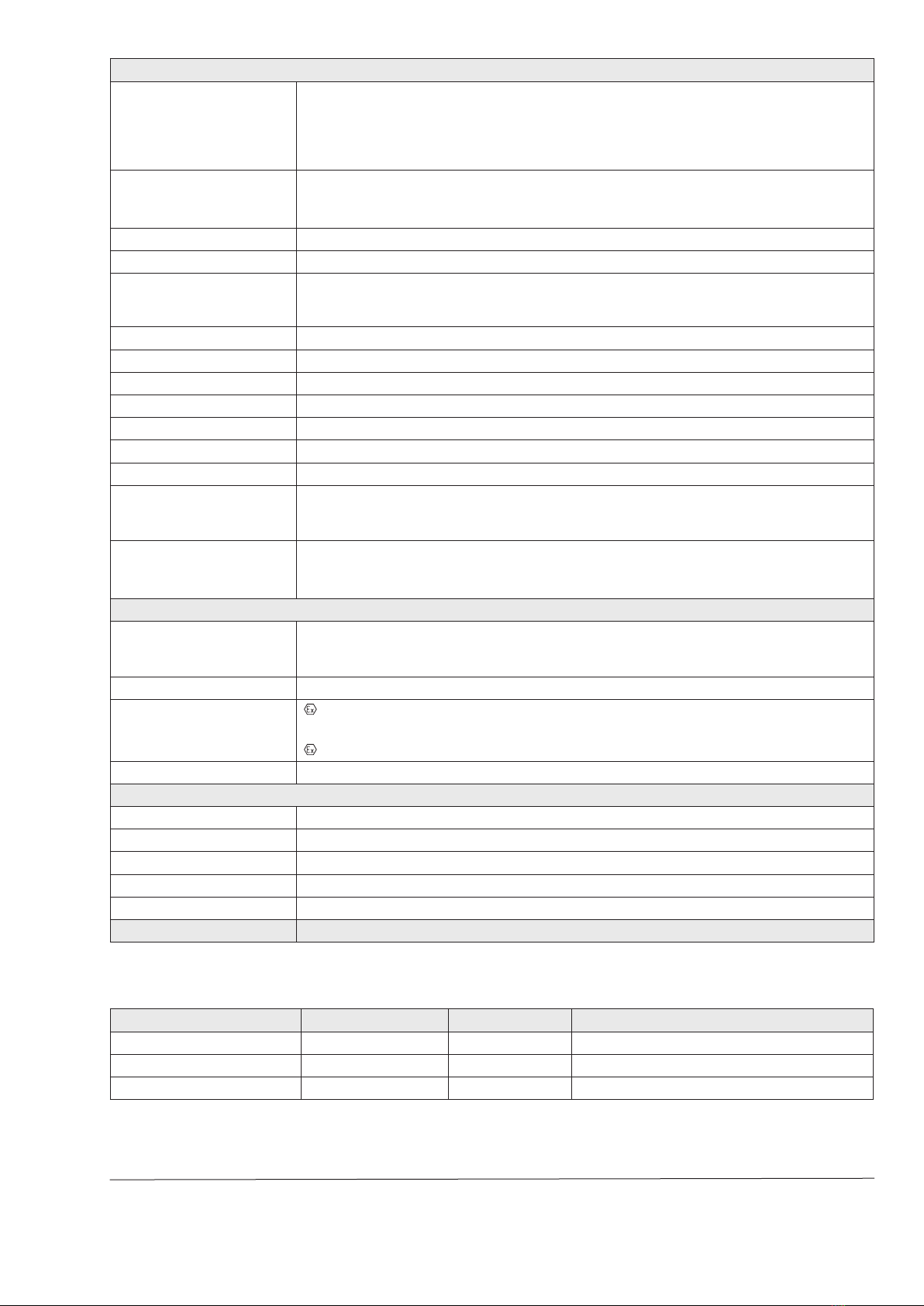
manuals.online logo
Brands
  1. Home
  2. •
  3. Brands
  4. •
  5. Samson
  6. •
  7. Valve Positioner
  8. •
  9. Samson 3725 series User manual

Samson 3725 series User manual

Data Sheet T 8394 EN
Associated Information Sheet T 8350 Edition June 2014
Fig.3: Type 3725, attachment to rotary actuators
according to VDI/VDE3845
Fig.2: Type 3725, attachment
to Type 3372 Actuator
Fig.1: Type 3725, direct
attachment to
Type3277 Actuator
The positioner ensures a predetermined assignment of the
valve (controlled variable x) to the input signal (reference vari-
able w). It compares the input signal received from a control
system to the travel or rotational angle of the control valve
and issues a corresponding output signal pressure (output
variable y).
Special features
•Simple direct attachment to SAMSON Type 3277 Actuator
(120 to 700cm², see Fig.1)
•Attachment according to IEC 60534-6 (NAMUR)
•Attachment to rotary actuators according to VDI/
VDE3845 (see Fig.3)
•Attachment to Type3372 Actuator for Series V2001
Valves (see Fig.2)
•Easy operation with intuitive navigation menu using three
capacitive keys
•LCD easy to read in any mounted position due to select-
able reading direction
•Variable, automatic start-up
•Preset parameters (only values deviating from the standard
need to be adjusted)
•Permanent storage of all parameters in EEPROM (protect-
ed against power failure)
•Two-wire system with a small electrical load of 300Ω
•Activatable tight-closing function
•Continuous monitoring of zero point
•Non-contact position sensing
•Unaffected by environmental effects and steam hammering
Version
–Electropneumatic postioner with local operation and LCD
–Type3725-000, without explosion protection
–Type3725-110, explosion protection according to
ATEX
–Type3725-113, explosion protection according to
GOST
–Type3725-130, explosion protection according to CSA
Series3725
Type3725ElectropneumaticPositioner
Application
Single-acting positioner for attachment to pneumatic linear
and rotary valves. Self-calibrating, automatic adaptation to
valve and actuator.
Referencevariable 4to20mA
Travel 3.75 to 50 mm
Openingangle  24to100°
2T 8394 EN
Principleofoperation
The positioner is mounted on pneumatic control valves and is
used to assign the valve position (controlled variablex) to the
control signal (reference variablew). The positioner compares
the electric control signal of a control system to the travel or
rotational angle of the control valve and issues a signal pres-
sure (output variabley) for the pneumatic actuator.
The positioner mainly consists of the following components
(Fig.4):
–Magnetoresistive sensor (2)
–Analog i/p converter (6) with a downstream booster (7)
–Electronics unit with microcontroller (4)
The travel or opening angle is measured by the external pick-
up lever, non-contact magnetoresistive sensor and down-
stream electronics.
The pick-up lever is connected to a magnet inside the device.
The motion of the pick-up lever causes the direction of the
magnetic eld to change. This change is sensed by the sensor
(2). The electronics unit determines the current position of the
actuator stem or opening angle from this information.
The position of the actuator stem or opening angle is transmit-
ted to the microcontroller (3) over the A/D converter (4). The
PD control algorithm in the microprocessor compares this ac-
tual position to the 4 to 20 mA control signal after it has been
converted by the A/D converter (3). In case of a system devi-
ation occurs, the activation of the i/p converter is changed so
that the actuator of the control valve (1) is pressurized or vent-
ed accordingly over the downstream booster (7). The supply
air is supplied to the booster and the pressure regulator (8).
Operation
A user-friendly, intuitive concept using three capacitive keys
and a LCD has been developed: Users select parameters by
touching the arrow keys and conrm the settings with the con-
rmation key. In the menu, all parameters are listed in one
level, meaning there is no need to search through submenus.
All parameter settings can be read and changed on site.
All values are displayed on the LCD. The reading direction of
the LCD can be rotated by 180°.
%
S
mm
%
mm
Q
34
11
6
7
810
1
w
9
x
y
2
5
1 Control valve
2 Sensor
3 A/D converter
4 Microcontroller
5 D/A converter
6 i/p module
7 Air capacity booster
8 Pressure regulator
9 Fixed restriction
10 Volume restriction
11 Display
Fig.4: Functional diagram of Type 3725 Positioner
T 8394 EN 3
Table1: Technical data
Type3725Positioner
Travel (adjustable) Direct attachment to Type 3277 Actuator: 3.75 to 30 mm
Direct attachment to Type 2780-2 Actuator: 6/12/15 mm
Attachment to Type 3372 Actuator: 15/30 mm
Attachment according to IEC 60534-6 (NAMUR): 3.75 to 50 mm
Attachment to rotary actuators: 24 to 100°
Reference variable w
(reverse polarity protection)
Static destruction limit
4 to 20mA signal range · Two-wire device · Split-range operation 4 to 11.9 mA and 12.1 to 20 mA
±33 V
Minimum current 3.8 mA
Load impedance Max. 6.3V
Supply air
Air quality acc. to ISO8573-1
Supply air: 1.4 to 7bar (20 to 105psi)
Max. particle size and density: Class 4 · Oil content: Class 3 · Pressure dew point: Class 3 or at least 10K
below the lowest ambient temperature to be expected
Signal pressure (output) 0 bar up to the capacity of the supply pressure · Can be limited to approx. 2.3bar by software
Characteristic 3 characteristics for globe valves · 9 characteristics for rotary valves
Hysteresis ≤ 0.3 %
Sensitivity ≤ 0.1 %
Transit time Only for actuators with initialization time > 0.5 s 1)
Direction of action w/x reversible
Air consumption ≤ 100 ln/h with a supply pressure up to 6bar and a signal pressure of 0.6bar
Air output capacity
Actuator lled with air At Δp = 6 bar: 8.5mn3/h, At Δp = 1.4 bar: 3.0mn3/h KVmax(20 °C) = 0.09
Actuator vented At Δp = 6 bar: 14.0mn3/h, At Δp = 1.4 bar: 4.5mn3/h KVmax(20 °C) = 0.15
Permissible ambient temperature –20 to +80 °C
–25 to +80 °C with metal cable gland
The limits in the test certicates additionally apply for explosion-protected versions
Safety
Inuences Temperature: ≤ 0.15 %/10 K
Inuence of vibrations: ≤ 0.25 % up to 2000 Hz and 4 g according to IEC 770
Supply air: None
Electromagnetic compatibility Complying with EN 61000-6-2, EN 61000-6-3 and NAMUR Recommendation NE 21
Explosion protection II 2G Ex ia IIC T4 according to ATEX
Intrinsically safe, Ex ia IIC T4 according to CSA Group
1Ex ia IIC T4 Gb X according to GOST
Degree of protection IP 66
Materials
Housing Polyphthalamide (PPA)
Cover Polycarbonate (PC)
External parts Stainless steel 1.4571 and 1.4301
Cable gland M20 x 1.5, black polyamide (PA)
Venting High-density polyethylene (PE-HD)
Weight Approx. 0.5 kg
1) For faster actuators, a volume restriction must be used. Otherwise, the initialization cannot be performed successfully.
Table2: Explosion protection certicates
Type of approval Certicatenumber Date Comments
EC Type Examination Certicate PTB 11 ATEX 2020 X 2011-08-25 II 2G Ex ia IIC T4
GOST certication RU C-DE.GB08.B.00697 2014-12-15 1Ex ia IIC T4 Gb X
CSA certication 2703735 2014-06-03 Ex ia IIC T4
Specications subject to change without notice
SAMSON AG · MESS- UND REGELTECHNIK
Weismüllerstraße 3 · 60314 Frankfurt am Main, Germany
Phone: +49 69 4009-0 · Fax: +49 69 4009-1507
[email protected] · www.samson.de T8394EN
2015-04-20 · English
Dimensions in mm
Article code
Positioner Type3725- xxx00000009999
With LCD and autotune, 4 to 20mA reference variable
Explosion protection
Without 0 0 0
II 2G Ex ia IIC T4 according to ATEX 1100
Intrinsically safe, Ex ia IIC T4 according to CSA Group 1300
1Ex ia IIC T4 Gb X according to GOST 1130
Mounting the positioner
The Type 3725 Electropneumatic Positioner can be attached
directly to the Type 3277 Actuator over a connection block.
When attached to the Type3277-5 Actuator (120 cm²), the
signal pressure is routed over an internal bore in the actuator
yoke to the actuator.
In actuators with fail-safe action “actuator stem retracts” and
in actuators with effective diaphragm areas of 240cm² or
larger, the signal pressure is routed to the actuator over
ready-made external piping.
Ordering text
Type 3725 Positioner
Attachment
Direct attachment to Type 3277 Actuator
(without pneumatic connecting rail)
Direct attachment to Type 3277 Actuator (120 to 700cm²)
Attachment according to IEC 60534-6 (NAMUR)
Attachment to rotary actuators acc. to VDI/VDE 3845
Attachment to Type 3278 Rotary Actuator (160/320 cm²)
Pneumatic connecting rail
G ¼ or ¼ NPT
Pressure gauge (max. 6 bar)
With or without
14
22
M20 x 1.5
157.5
108
87
42
21
62.50
25
14
22
M20 x 1.5
157.5
108
87
42
21
62.50
25
14
22
M20 x 1.5
157.5
108
87
42
21
62.50
25

Other manuals for 3725 series

3

This manual suits for next models

4

Other Samson Valve Positioner manuals

Samson 4763 Service manual

Samson

Samson 4763 Service manual

Samson 3767 Setup guide

Samson

Samson 3767 Setup guide

Samson TROVIS 3730-3 Service manual

Samson

Samson TROVIS 3730-3 Service manual

Samson EB 8075 EN Service manual

Samson

Samson EB 8075 EN Service manual

Samson 3730-3 ESD Service manual

Samson

Samson 3730-3 ESD Service manual

Samson 373 Series User manual

Samson

Samson 373 Series User manual

Samson TROVIS 3730-3 User manual

Samson

Samson TROVIS 3730-3 User manual

Samson TROVIS 3730-1 Service manual

Samson

Samson TROVIS 3730-1 Service manual

Samson 4763 Service manual

Samson

Samson 4763 Service manual

Samson 3730-2 Service manual

Samson

Samson 3730-2 Service manual

Samson FOUNDATION 3730-5 Service manual

Samson

Samson FOUNDATION 3730-5 Service manual

Samson 3730 Series Service manual

Samson

Samson 3730 Series Service manual

Samson 3730-6 Instruction sheet

Samson

Samson 3730-6 Instruction sheet

Samson TROVIS SAFE 3730 Series User manual

Samson

Samson TROVIS SAFE 3730 Series User manual

Samson 4765 Service manual

Samson

Samson 4765 Service manual

Samson 3730-4 User manual

Samson

Samson 3730-4 User manual

Samson 3731-5 Service manual

Samson

Samson 3731-5 Service manual

Samson TROVIS 3730-3 Service manual

Samson

Samson TROVIS 3730-3 Service manual

Samson 3730 Series Service manual

Samson

Samson 3730 Series Service manual

Samson 3725 series Service manual

Samson

Samson 3725 series Service manual

Samson TROVIS 3731-3 Service manual

Samson

Samson TROVIS 3731-3 Service manual

Samson 3730 Series Service manual

Samson

Samson 3730 Series Service manual

Samson 3730-4 Service manual

Samson

Samson 3730-4 Service manual

Samson TROVIS 3731-3 Service manual

Samson

Samson TROVIS 3731-3 Service manual

Popular Valve Positioner manuals by other brands

KMC Controls CMC-1002 installation guide

KMC Controls

KMC Controls CMC-1002 installation guide

GEM 650 Installation, operating and maintenance instructions

GEM

GEM 650 Installation, operating and maintenance instructions

ABB AV1 operating instructions

ABB

ABB AV1 operating instructions

Videotec NXPTZT instruction manual

Videotec

Videotec NXPTZT instruction manual

KAUP 3T450A operating manual

KAUP

KAUP 3T450A operating manual

Leuze BPS 8 Technical description

Leuze

Leuze BPS 8 Technical description

cascade corporation L Series user manual

cascade corporation

cascade corporation L Series user manual

metso automation IMO-596 Installation maintenance and operating instructions

metso automation

metso automation IMO-596 Installation maintenance and operating instructions

SCHIEBEL SRG2 Series manual

SCHIEBEL

SCHIEBEL SRG2 Series manual

SMAR HART FY500 Installation operation & maintenance

SMAR

SMAR HART FY500 Installation operation & maintenance

Pepperl+Fuchs PCV F200-B17-V1D Series manual

Pepperl+Fuchs

Pepperl+Fuchs PCV F200-B17-V1D Series manual

Baileigh WP-750 Operator's manual

Baileigh

Baileigh WP-750 Operator's manual

tissin TS800 Series instruction manual

tissin

tissin TS800 Series instruction manual

GEM 1435 ePos operating instructions

GEM

GEM 1435 ePos operating instructions

tissin TS800 Series instruction manual

tissin

tissin TS800 Series instruction manual

Gemu 1436 cPos eco operating instructions

Gemu

Gemu 1436 cPos eco operating instructions

Dresser Masoneilan SVI II AP-2 quick start guide

Dresser

Dresser Masoneilan SVI II AP-2 quick start guide

ABB TZIDC-200 operating instructions

ABB

ABB TZIDC-200 operating instructions

manuals.online logo
manuals.online logoBrands
  • About & Mission
  • Contact us
  • Privacy Policy
  • Terms and Conditions

Copyright 2025 Manuals.Online. All Rights Reserved.