Onan LTC Series Product manual


TABLE
OFCONTENTS
TITLE PAGE
Drrcription 3
tnsro
llotiol 6
0perotion 12
[oinf
monsr 11
Podr Infomotlon 2l
ONAN
LOAD
TRANSFERCONTROL
' .)
DEL
959-3 LTG 2457
GENERAL
INFORMATION
For
lutun
rdrrencl,
lill tr thr blonlr
bdow:
cmbol Hodel ltom,foit L-f L \et
Serial Nmbet t .t91 4 I
Wfuin(Diaban @iagaa ftrnisted vith qftol)
(t
l9 t \'t,- I
Inslo,lled
WDate
ITPORTA}II...RIIURJI
WARRA]ITY
CARD
ATIACHED
IO UIIII
,',i'
I
:.
;{i
i r.,,
e'I
Sr
r:i ^ ,: "iiill' ...
:.,r, i, .: ' . "-!
I
I
t.
,*

INTRODUCTION
This Onan
LTD series manual
ccntains information
to
help install, operate,
and maintainline transfer
con-
trols. Keep this nranualhandy'
and refer to it when
necessarv. The load transfr:rcontrols describedin
this manual
are designed
to be used with Onan
2*ire
control remotestarting generating
plants. When
con-
tacting a dealer or the factory about this control,
always supplythe complete
Modeland
Spec
No.,
plus
the full serial numberas shown on the nameplate.
This informationis necessary
to identify the control
among the many basic and special optional tl'pes
manufactured
by Onan.
MODEL
DESIGI.IATION
EXAMPLE.
LTC2OO.23/1A
AF spr. Letter Advances with procluction
modification resulting in parts not inter-
changeable.
lF spr" No.
- Identifies
optional
equipment.
No. 1 designates no
advertised. optionsor basic as
Z
D--- Diagonal - Separates basic model from
specification.
3[\- Coc]e
No.
(Units Digit)
- Designatesvoitage,
wire
and
phase.1is 120-volt;
2is 24[fvolt;
7 is I20/240-volt
l-phase;
4 is 120'208-volt
4-wire3-phase;
5D is I20/24gro1t
4wire
3-phase
delta,
center
tapped.
2l\ code No.
(Tens
Digit)
- No.
2designates
con-
2OO
Dl>- , mpete
Ratin(.
LTC[--- Serie.s
- LTC Designate
s OnanLoad Transfer
'lontrol for 2-wir: remote
charging
system.
trol serves for both
considered
standard.
6Gcycie use only.
cycle use
only.
5G or 6Gcycle and is
No.
omitted
designates
No. 5 designates5G
TYPICAL MODEL
LTC
MANUFACTURER'S
WARRANTY
J'he Manufacturer rr,,arrants, to the original user, that each
product of its manufacture is free from defects in material
and factory workmanship if properly installed, serviced and
operated under normal conditions according to the Manu-
facturert s instructions.
Manuf acturer's obli6iation under this warranty is lirnrted to
correcting without charge at its factory any part or parts
thereof which shall be returned to its factory or one of its
Ar:thorized Service Stations, transpg*ation charges prepaid,
within one year after being put irlto service by the original
user, and which upon examination shall disclose to the
Manufacturer's satisfaction to have been originally def ective.
Correction of such defects try repair to, or supplying of
replacements for defective parts, shall constitute fulfillment
of all obligations to original user.
This warranty shall not apply to any of the Manufacturer's
products which must be replaced because of normal wear,
which have been subject to misuse, negligence or accident
or which shall have been repaired or dltered outside of the
Manufacturerrs factory unless authorized by the Manufacturer.
Manufacturer shall not be liable for loss, damage or expense
directly or indirectly from the use of its product or from any
cause.
The above warranty supersedes and is in lieu of all other
warranties, expressed or implied, and of all other liabilities
or obligations on part of Manufacturer. No person, agent or
deeler is authorized to give any warranties on behalf of the
Manufacturer nor to assume for the Manufacturer any other
liability in connection with any of its products unless made
in writing and signed by an officer of the Manufacturer.
DATED AUGUST
l, 1963
rl
sirut
24-vo1t
battery

TIME
DELAY
RETRANSFERRELAY
(Optional)
o
o
o
VOLTAGE
RELAY SENSITIVE
(Optional)
SWING
OUT PANEL
BATTERY
CHARGING
CURRENT
METER
L----).
r f o
BATTERY CHARGING
CURRENT ADJUSTMENT
FUSE
TIME
DELAY
RELAY
STARTING
(Optional)
BATTERYHI.CHARGE
LIGHT
EXERCISER (Optional)
HI-LO CHARGE SWITCH
OPERATION SELECTOR
swtTcH
REMOTE CONTROL
CONNECTTONS
TRANSFER SWITCH
NEUTRAL BAR
(Optional on Most Models)
FIG.
I
L
TC200

S\t,ING
OUT FUSE
PANEL
BATTERY CHARGING
CUPF
F'NT
METER
./OL
iAGE SENSI'TIVE
RELAY
Back of Panel Unless
USS
arrd
OSS (Optional)
BATTERY
CHA,RGING
CURRENT
ADJUSTMENT
TIME
DELAY
RELAY
RETRANSF
ER (Optional
tl
ilfTRANSF
E
R
swtTcH
NEUTRAL BAR
(Optional)
r:
XEF.CISE
R
(Optional)
TIMEDELAY
RELAY.STARTING
Back
of Panel (OPtional)
REHOTE CONTROL CONNECTIONS
HI{-O CHARGE SWITCH
BATTERY
HI.CHARGELIGHT
LTC400
FIG.
2
5-.
;
.'
:
i
t
-'
4>
I -.:'

DESCRIPTION
The Onan series LTC (load transfer control) is designed fot
use with Onan 2-wire, 24-voLt,remote-starting, generating
plants installed for standby service. The LTC controls
generatingplant operation, supply of c-ommercialand emer-
gency powerto the load. It assures a supply of emergency
powerduring commercial
powerfailures.
CIRCUTT
& COMPONENTS
The basit:
LTC includes:
1. Load transfer switch that connects either the commer-
cial or emergency
power
to the load.
2. Relaysto start andstop the generating
plantand control
the bansferswitch.
3. A battery charga which maintains
starting batteries at
full-charge.
NOTE: Use the wirin! dia(,ran lumished with the control
in conjunction with flis explanation (wirin{ diagams
explained in [vtaintenanceSection).
0perotion - (Mechonicolly
Held Tronsfer
Swirch):
The frans-
let switch is electrically operated and connects the load to
commercial or emergency
power source. An LTC's current
rating is determinedby the transfer switch capacity.
All transfer
srvitchescontain
two separate
sets of contacts;
one set connectsthe commercialiine to rhe load, the other
connectsthe emergency
powerto the load. A pull-in coil
(when energizedby line power) pulls in the lineside con-
tacts. A mechanicallatch then locks the contacts
closed
and opensa micro-switch
that disconnectsthe pull-in coil.
This eliminateshum
duringnormaloperation.
Anothercoil (energized
by plant output) operatesthe mech-
anical latch release,disconnecting
the line-side contacts.
These contacts must unlatch and drop out before the gen-
erator
contacts
can close. Powersuppliedto this coil also
pulls in and holds the generator
contacts closed. Both
mechanical
and electrical inter-locksprevent
contactsfrom
closing
at the same
time.
The 6asic control circuit consists r.;f
I
hre,erelavs:
1. Start-stop
relay
2. Transferswitch pilot-relay
3. Instant
transferrelay
In addition,
it may
contain
someoptionalrelays. The start-
stop relay controls starting and stopping of the generating
plant. Whenthe relay de-energizes its contacts signal the
engine control to start and run the plant. The transfer
switch pilot-relay controls the mechanical latch release
coil and the generator
side of the bansfer switch. When
the
pilot-relay energizes, it releases the latch and connectsthe
coil that pulls in the generatorside of the transfer switch.
The instant transfer relay conhols the lineside of the trans-
fer switch and also the generator side. Whenever
this relay
is energized from line power, it breaks the circuit to the
generator side and energizes the line-side of the transfer
switch.
Normally (with cominercial power on) the transfer switch
line-side is closed. The start-stop relay and instant trans-
fer relay are energized; the transfer switch pilot-relay is
de-energized.
When conrmercial power fails, the start-stop and instant
transfer rr:li1s de-energize. This closes the start-stop
relay contact, signaling the plant to start. Whenvoltage
builds up,the hansferswitch pilot-relaypulls in, energizing
the latch r.lisconnect
coil and generator-side
coil. The main
line contacts open, generatorcontacts close, and the gen-
erator supplies powerto the load.
When commercial power returns, the instant hansfer relay
closes which disconnects the generator side coil of the
transfer switch and allows the line.side to pull in immedi,
ately. At the same time, the start-stop relay energizes to
stop the generating
plant.
High Rote Bottery Chorger: This charger
includes a high
rate of about 2-amps
to boost low batteries and a low rate
(100 - 500 milliamp, adjustable with rheostat) to maintain
batteries once charged. Both are controlled by a toggle
switch on the inner panel. A light indicates when the high
rate is on; the meter indicates the low rate charge cunent.
Load Tlzrnsfet Control LTC800-1200 is contained in two
separatecabinets,
one cabinet containsthe control relays,
battery charger, and
optionalequipment.
The othercabinet
contains the transfer switch. The transfer switch is rated at
8ft)- or 120Gamps
and has non-tripping circuit breakers
actuated by small electric motors. A mechanical interlock
(on the backof the switch) prevents
line and
generator
contacts frombeing closed at the same
time.
5-.

OPTIONAL
EQUIPMENT
Only the most popular options are discussed here.
Time Deloy Reloys: A time delay is often required
in one
or more of the control functions such as engine starting,
load pickup, engine stopping, load transfer to commercial
line. Two different types of relays are used, dependingon
the function to be delayed and the required delay period.
(See Adjustnents in the Maintenance Section for complete
relay delay descriptions.)
Tine Delay on Staftin(: Delays plant starting after a power
failure. It prevents plant operatiorrduring very short line
failures.
Time Delay on Load Pickup: Delays the transfer of the load
to allow for plant warmup.
Tine Delay on Re-frans/er: Allows time for the returning
commercial power to stabilize before connecting it to the
load. The plant suppliespower
during
this period.
FIG.3
Time Delay on Stoppin( (A|tet Re-/rans/er); Allows the plant
to run for a few minutes under no-load before shut-down.
;!; stabilizes engine temperature,
reducing
distortion and
VoltogeSensitive
Reloys: The basicconhol reacts
only to
complete failure (about 5V" of.
nominal line voltage). Volt-
a6!esensitive relays allow it to react to any pre-set voltage
dropandalso to higher
than
normal
voltages.
Each voltage sensitive relay consists of a direct current
relay connectedacross the output of a half-wave
rectifier.
.q capacitor (connected across the output of the rectifier)
maintains current flow during the half cycle that no cunent
flows through
the re,ctifier.
The pickup control consists of a wire-wound
potentiometer
which is connected in series with the rectifier and relay
coil. The pickupcontroloperates
by increasing
or decreasing
current-flr-,w
through the relay coil. The dropout control
consists of a wire woundpotentiometer
in parallel with the
relay coil. It operates by increasing or decreasing
the
current by-passed around the relay coil. Increasingthe
by-passed
cunent lowers the dropout voltage. Both pickup
and drop-out voltages are adjustable. In under-voltage
application, the relay is connected
across the line. When
line voltage falls to the drop-out point, the relay de-
energizes,starting the hansfer to emergency
power. When
line voltage returns to the pre-set pickup voltage, the relay
initiates the return to commercialpower.
In over-voltageapplication the relay is normally closed, but
whenline voltage
becomes
excessively
high,
therelayopens,
initiating the transfer to generator
power. When
line voltage
drops to normal, the relav returns the load to commercial
line power.
Ttreserelays can also be usedto disconnectthe generator
in applications where low voltage could damagethe load
equipment.
A non-adjustable voltage sensitive relay is available.
Though it is similar in operation,
the non-adjustable
relay
operates
at fixed voltages (drop-out
at 70%
of line voltage
and pickup at 90%). [t can be usedonly for under-voltage
protection.
TABLE I - Moximum
ond
Minimum
Seilingsof0NAN
Adiustoble
VoltogeS
ensitive
Reloys
Non-odiustoble
Low VoltogeSensitiveReloy: ke-set to
initiate transfer to standby power at 70%
of normd line
voltage
and
back
to the line at 90%.
Adiustoble
Low Voltoge
SensitiveReloy: Initiates
transfer
to standby between
54%and96%of.normal
line voltage, and
between 7Vo and l\Vo on retransfer to the line. Minimum
voltage differential is 5%, and maximum
is 17%
of normal
line voltage.
Adiusloblc
HighVoltoge
Sensitive
Reloy: Initiates
transfer
to standbybetween105%
and llSvo of normal
line voltage,
and between 100%and lll% on re''transfer
to the line.
Minimum
voltage differential
is 5%, and maximum
is 17qoof.
normalline voltage.
Mechonicolly
Held Contocfs:
(Generator
Side)
maybe speci-
fied on all ampswitches. Mechanicallyheld contacts on the
line side are standard.
Exerciser: The exerciserautomatically
starts the plant at
regular intervalsand allows it to run for a pre-set
time. It
may be orderedso the plant operateswith or without normal
load (depending
onthe installation).
This assrues
emergency
starting by keeping
the luel system
filled and the batteries
charged. In the even:of a power
failure while the phnt is
exercisingat no-load,the conhol immediately
switchesthe
loadto the generating
plant.
x/c
c
N/o
PICK
UP
CONTROL L2
DROP
OUT LINE
L1
CONTROL
TYPE RELAY GEN.STARTING GEN.
STOPPING
Under-Voltage 54vo
to 96%of 70Voto 100%of
Normal
Voltage Normal
Voltage
ioor". ilt" "t
Over-Voltage 105%
to l15%of 100?oto lll% o
Normal
Voltage Normal
Voltage

Auxiliory Conlocls: Extra single-pole double-throw
contacts
are mounted on the transfer switch. Rating is: Gamp at
l2Gvolts, 3-amp at 24$volts, and 1.9amp at 48$volts.
These contacts are used for signal circuits'
Signol
Lights ond AlormTerminols:Available as a warning
of
...commercial power failure...the standbyplant has
started and is supplying the load. . .and other conditions
important
to your ;rpplication.
Simuloted Power Foilure Test Switch: This manually
operated switch starts the plant and allows it to assume
the normal load. The switch is normally on and will start
the plant when switchedto o/f.
0perotionSelector
Switch: This switch is similar to the
selectorswitch on the generiitirig
plant control box and has
the samefunctions. Its three positions corrhol the plant
from the load transfer control. In sfop psition, the plant
will not :;tart upon line failure. For autonratic operation
set it an automatic. Checkposition starts the plant without
assuming
theload
fcrtesting.
Fully Automotic SotteryChorgers:
Using SCR
(silicon con-
trolled rectifier) are constant voltage, current limiting
chargers.Designed for float charging Lead-Acid or Nickel-
Cadmiumstarting batteries.Transistorized
units, complete
with built-in Equalize Charge Timer. A permanently con-
nected battery continuously floats at a constant voltage.
As the battery approaches
full-charge,preset voltage, the
chargingcurrent automatically tapers to zero amperes
or
to the steady-state load on the battery keeping starting
batteries
fully charged.For fast charging,
manuallyset the
equalize-charge timer for any time period up to 12 hours
(Most
Lead-AcidBatteryManufacturers
recommend
24hours
of equdlize
chargingevery
month).
Settingthe Timer raises
the charger's output voltage and maintains the higher
charging voltage for the time selected. At the end of the
tined interval, the Timer automatically
switchesbackto
float voltage.

INSTALLATION
ONAN recommends
that load transfer controls be installed
by an experienced
electrician, observingall normal
safety
precautions
andlocal codes.
LOCATINGTHE
CONTROL
The point at which the load transfer cuts into the existing
electrical circuit varies accordingto application and type
of entrancer
switch. There must be a switch and fuses in
the commercial line before the control. Both the generator
output and ltrad
should be similarly protected. To provide
maximumplant protection, have a fused switch or circuit
breaker
with thesamecapacityandelectrical characteristics
as theplant connectedbetween
the loadtransferconhol and
p
lant.
When a standby plant protects the complete electrical
service, it is normally installed betweenthe main entrance
switch and the disbibution panel (Fig. 7). If the protection
is limited to a single emergencydistribution panel, cut inb
the circuit after the entranceswitch fuses for the emergency
distribution
panel
(Fig. 8).
If the entrance switch is of the compacttype where branch
and main fuses are in a single cabinet (such as used in
most modern
homes)cut into the main entrance betweenthe
meterand switch. Then install an additional fused switch
ahead
of the load transfer control (Fig. 6t.
LOAD WIR
ES
METER LOAD
TRANSFER
CONTROL
PLANT
CONTROL
BOX
r-,i.dE
FROM
SERVICE
ENTN
ANCE FUSED
swtTcH
BOX
REMOTE
CONTROL
WIRES
'-----
WIRES
FROM
GEN.
SIDE
OF TRANSFERSWITCH
.tt-'--t-
I
I
I
I
I
i
I
LFIG.
4

r- -- 4z-1
LTC 100
LTC 200 L
TC 400 L
TC 800
LTC 1200
I
i
II
I
*"
I
I
't
I
e
tI
IT
|l
tl
_t'
II
sl
T--
\tN
o\
I
2c - --J I
iFll
rer
-r!
l'2
II
I
R
tIzUNTING
lOtrS@ I
\
t_ lH)uNrlNG ltolEsC)
t1
TI
tl
t;-l
il
I
TI
ll
2-e
CABINET Afl
ll
II
tl
-l
A,/ T
l__t_
p3
_-,-L
II
I
i
I
lB-1 | -^
+<H
I ""
:o --4
T'60"LTC8OO
x'66"
Lrc /200
CABINET
B
I
i
I
I
I
I
NT
FIG.
Line-Lood-Generolor
Wiring: All lo''rri
wiring should be
perfornred
to meetlocal elechical codes. [Jsewires heavl,
enough
to carry the controls rated cu:'rent. The details of
wiring the load, line and generating
plant, wi
Il depend
on
their electrical charapteristics: number
of pha:;es,
voltage,
and numberof wires. In all cases, the load, line and gen-
5erator, will be connected
directly to the controlbansfer
switch. Thecorrect
positions
for connection
aremarkedon
the
transfer
switch
Qgen,
load,Iine). Follow
the
instructions
given
under
eachdrawing
shown
herefor thetranderswitch
with
your
specific
electrical
characteristics.
ADDITIONAL
FUSE
D
swtTcH
/
CONTROL
[ ."- TRAISFER
-1
MAIN POWER
SUPP
LY
LI
NE
IIAB
LAB
AB GEN.
LOAD
I
1
I
J
_J t-
L
L
coMPAcr
rypE /
ENTRANCE SWITCH
/
INSTALLATION USING COMPACT ENTRANCE SWITCH
FIG.
6
7

-l:- SERvlcE
I swrrcu
I
--{ f+/ l -LOAi_r
rRANSF
ea.T FUSES
OR
h l i b coNrRoL fclRculrBREAKER
f
__l_+_l
_._ _ \ (rvhen Used)
ryyt_en r I l-l
lTl ----_-l )r'-
SUPPLY t-- --l rllll | /',
PowER I ; I-l1tl-'------t )-g:T"a
sihi& L- --j illll M^-,;;;;l
illll lfffi8 PowER
I
illil illrfr;"PLANr!
L
NE
il+tf
--i-llrl
"'"" - J
fli--ri-1rl
"',-
lA
Bc n
sC,i
| __ ^rrvll
I A
Bc:l
LOAD
l--- ---J+rj! |
I orsrnreurroN
I
A cABINET I
tNsrALLATroN
BETwEEN
ENTRANcE
AND
DrsrRrBUTroN
pANEL
-- - _J r r
-FIG.
Ihe load selected for operation during emergclncyservice
rnight
happen
to be servedby only one
of the two lol line
wires. In that case,half of a 120/240-volt
gene:ator
would
be 100%overloaded,
the other haif idle. 'firis can br,
remedied
bv rewiring the fuse box::o the loao
to be oper-
ated duringernergencl,is
served
e.qualiybr each
of thetrvo
fiol wires.
CONTROL
MOUNTING
The load transfer control is normalll supplied rn a NEMA
Type l box for indoorwall mounting. It shouidbe protected
frnm excessive heat. mcisture,
dust. anC
dirt. Mountthe
control on a vertical wall, switchboard,or otherpermanent
support
whereit will notbe
subjectedto excessive
vri'ration.
Secureit with bolts or screws throughthe holes provided
in
the
back
of box(nig. 5).
WIRING
Before rviring the controi, provide the cornmercial
power
line with ersuitable
switch and fuses (or circuit breakers)
aheadof the load hansfer. All loadcircuits shoulci
llso be
7
properly
fused. Install and operate
the plant from its own
controlsbefore
vriring
the loadtransfer
control. Load trans-
fercontrol
wiring
ean
he
accomplished
in twosteps:
f
. ilire conhol between
control
andgenerator
set.
2. Wire
load from line, generator
set, and load, to the con-
trol If conduitis used,
run
thecontrol
(low
voltage)
and
load
wiresin separate
conduits.
Contro!
Wiring:
Three
control
wires
connecttheload
transfer
control and generator
set {rotmd, B-f, and remote. For runs
up to l0Gfeet, use #14
wire; for longerruns, use larger
rvire
as specifiedin the plants manual. If possible,
colorcode
the wires using
the followingcolor code
for uniformity.
Control
Circuit ColorCode: B+..........Green
Ground......White
Remote.....
Red
Connect the wires from the terminal block in the load
transfer control to the remoteterminal block in the plant
control box, 9+ to B+, {round-to-{round, and remote-to-
remote
(Fig. 9).
MAIN
POWE
R
SUPPLY
METE
RI At
ENTRAN
CE
SwtTcH
DTSTRIBUTION
I
PANEL I
FUSES FUSES
OR CtRCUlr ,-- - - -,
I BREAKER (when
used) - -q
ir--]--\i i
A STANDBY
I powER
-ttllll--i---r
--+lll lll-.!-----{-6{D pLANr I
tl
lll lllll u -J
LrNE
tlfIIf -- -i
ttll "r*.
I
l^
u' I
lill
,
STANDBY
INSTALLATION
FOF
EMERGENCY
DISTRIBUTIOI{PAN
E
L - -.
- -j lii '',ao
IIJJ I F-.
r-oau
-THc;a"r."rr"l1
LLrAU llL:f__TF''"eUERGENCY I
TRANSFER
I L__t E orsrnlBurtoN I
L-su:--r-a:_;s'r:l
FIG"
8

CONTROL
GND
B+
REMOTE
PLANT CONTROL WIRE CONNECTIONS
I PHASE,
2
WIRE
3 PHASE,
3 WIRE
L nemotE
coNTRoL
WI
RES
B+ GREFN
GND WHITE
REMOTERED
FtG.l0
FlG.
|
|
I
I PHASE,3
WIRE
I
I STANDBY
POWER
I uNtr
coNTRoL
Box
FIG.
9
M
AIN
POWE
RSTANDBY
POWER MAI
N
POWER STANDBY
POWER
3 PHASE,
4 WIRE
MAIN
POWER STAN
DBY
POWER
M
AIN
POWER STAN
DBY
POWER

MAIN POWER
SUPPLY
74O 120
v. v.
lf neutral is to be grounded, connect
ground to neutral bar. lf ine switched
neutral option is inclujed, the neu-
tral wires f
ronr the i-enerator. line,
and load should t:e <;onnected to the
remaining terminal in each respective
section of the transfer svrrtch.
r20
V.
r NEUTRAL
r20-v.
LII{E
LINE
TOSTANDBY
POWER
UNIT
TOSTANDBY
POWER
UNIT
GEN.
LOAD
NEUTRAL BAR
OPTIONAL--'=a
STNGLE-pHASE,
3-WlRE,
120/240-VOLT
FrG.
12
MAIN
POWE
R
SUPPLY
TOSTANDBY
POWERUNIT
THRE
E-PHASE,
FlG.
I
3
iI
t
i
t20-v.
t20-v.
240-V.
HAIN POWER
SUPP
LY
Three legs connect to the lrne srde
of thc transfer switch anC all 'etrtrrl
wires are connected to the optron:rl
neutral bar in the load transfer
cabinet. lf tlre control is not so
equipped, ground wirr:s can be
connected wi th solderl t:
5s
connectcrs
and taped.
NEUTRAL BAR OPTIONAL
FfG.
14
THREE-PHASF.4-WIRE
r0

CHECKING
PHASE
RELATIONSOF
A
3.PHASE
STANDBY
Phase relationships determinethe direction of rotation of
any 3-phase motor. Phase relations must be correct if
motors are to rotate in the proper direction under both
normal
and emergency
power. Always checkphase
relation-
ship as follows before operating generatoror connecting
line to load.
Connect a lphase motorto the load terminals(and power
to the line side of the transfer switch) and check motor
rotation. If the direction of rotation is correct, the lines
phase relationship is correct. If it rotates in the wrong
direction, change
the direction of rotation by reversing
any
two of the threemain
phase
leadsconnected
on the transfer
switchline-side.
Next, turn off the main
power,start the generator
and check
motor rotation when powered by the generator. If the
direction of rotation is wrong, conect it by reversing any
two of the three main phase leads on the generator
(GEN)
side of the transferswitch.
THREE.PHASE
SERVICE
ANDASINGLE-PHASE
STANDBY
In some cases, emergency
singleahase loads connected
from one leg to ground of a 4-wire .lphase service can be
protected by a singlephase generating plant and load
transfer control. This is often done in institutions where
all emergency lights are connected from one l"g of the
4wire service to ground. The load transfer control used
for this service should be wired to the generatingplant
with the leg of the commercial
power to be protectedby
stand-by power connected to the line side of the transfer
switch.
Wiring this type of conhol can become
a complicated
pro
cedure, depending
on the electrical service, the problems
of Sphase balance, and a knowledgeof the loads to be
operated during a power failure. It should be attempted
only with a thorough knowledge of the buildings electrical
service. If questions arise conceming,
the useor installation
of a control in this type of service, contact Onanfurnishing
full informatiur.

OPERATION
when the operation Selectorswitch is used in conjunction
with the plant control switch, the following points should be
noted. The plant conhol switch predominates. when it is
on sfop, the plant stops and cannot be started from the
toad transfer. Whenit is on run, the plant cannot be
stopped from the load transfer. To control the plant from
the load transfer, set the plant switch on remote. The
Operation
Selector
switch will then start and stop the plant.
Before settlng the plant for remoteoperation, test it by
setting the plant csntrol switch on run. The plant should
start (but not take over the.
load) unless the commercial
line fails. With the commercial
power connected
to the
control, set the plants switch at remote. The control is
now ready for autonraticoperation and will start if commer-
cial power
fails. As a test, the entrance
sw,itchof commer-
cial iower can be opened. The plant should start and
supply
the load.
0PERATI0N
SELECT0R
S\VITCH
(Optionol)
The operation selector switch allows the plant to be con-
holled fromthe load transfer
control. It is a three
positron
switch: In the check
position,the plant starts and runs
but
does notassumethe load
unless
a line fail'.ueoccurs. Use
this posilion for manual
plant excrcise. Tircs/op position
shuts down the plant and prevents
it from
sturting. Use
this position for plant repairsandservicc, The automatic
position allorvs the plant to assume
the lo;rdwhen
a line
failureoccurs. This is thenormal
po.ition (or
automatically
starting and stoppingthe standby
plant.
TIME DELAY RELAYS
(Optionol)
All time delay
relaysare set at the factory. Unless
other-
wise stated in the order
specifications,relays are set as
shown in Table ? If necessary,these settings can be
adJusted
(see l/ainf enmce).
TAdLE
2
. TIME
DELAY
RELAYSTANDARD
SETTINGS
(Unlesr Othc:wlsa Spoci!'ledIn Ordor)
BATTERY
CHARGING
CIRCUIT
Set the trickle chargerto maintain the plant batteries at
full-charge. This can best be done by setting the battery
charger and checking the battery condition for several
weekswith a hydrometer.
Adjustthe charger
for theminimum
chargerate that wrll rnaintain charge condition. Higher
rates will shorten battery life. Large ambient
temperature
changes
wiil probably
require
charger
adjustment.
EXERCISER
CLOCK
The exerciser
clock requires
settingto determine
the number
and length of exerciseperiodseach week. It will operate
theplant
for any
multipleof 1$minutes
per
day
for as many
days as is desired
. Onan
recommends
running
the plant for
at least
3Gminutes
once
a week. Running
theplant for
one
long period
each
weekis better
thanseveral
short
periods.
FrG.
l5
The clock is equipped
with a 24hour dial (light half for
day hours,
shadedhalf for night).
Ten trip-pins
aresupplied
with theclock for a maximum
of five operations
daily. An
operation
is set in the following manner: A trip-plnplaced
in the inside
rowof holes
starts
the plant;
a pin in the
out-
side
row
stopsthe
plant.
The specific days the plant is to operate
are set on tne
spoked
wheelbeiow
the
daily dial. place
a trip
pin in each
spoke
for which no ererciso period
is desired. Example:
l0 l'1ln
- Hagen I
;;;";;l
EXERCISE
CLOCK SET TO START
PLANT AT 9 P.M. EACH FRIDAY
AND STOp lT AT t0 p.H.
Dclay In starting
Dclay on load plckup
Delay on retransfer
Delay
on plant
stopping
-after
retransfer l0 Mln - Hagon i
t2

Fig. i5 showsthe,-lock set to exercisrr
ihe plant for 9:00
tc 10:00P.M. Fridav rright. rrVith
the prns
in place,
sei the
c,ock for the correctdav and time. To set the day, turn the
spoked wheei to aiiarr the correct day with the small day
pointer on the spoke spring. To set thr: tirne, loosen the
Ielt hand threadoral lock-nut
and turn the rlial by handto
the correct time. After setting the conect time, tighten
dial nut.
t3

MAINTE}IANCE
PERIODIC
SERVICE
At regular intervals inspect inside the cabinet for dust.
Clean as required. Always keep the cabinet clean. Dust
and dirt can cause hum,irregular operation,or even a com-
plete breakdownof the system. At the sametime, inspect
wiring for loose or dirty connections.
OX&{
WIRING
DIAGRAITS
The wiring diagram fumished with every lmd bansfer
control is your key to the control. Keep it vith the onhol.
Use the wiring diagram:
1. To explain control operation
2. To obtain part nunbers for ordering repair parts
3. To deternine the function of all components
4. To aid in coatrol repair
Here are somehints on reading wiring diagrams.The Onan
wiring diagram
is a semi-pictorial. [t shows all components
in their approximate
position and namedby function, i.e.,
time delay on starting relay and the start-stoprelay. The
relative positions of the terminals
on each component
are
the sameas you see them in the control. All relays are
shown d*arct(ized unless otherwise noted. The outside
enclosure metal is shown in dotted lines. Each view is
tabeled to indicate the direction of viewing and location.
For example:Panel Rear View (inside panel as seen
from
the rear).
FtG.
l5
ADJUSTMENT
0F
VOLTAGE
SENSITIVF
RELAY
(Oprionol)
Undcr-Volfogc
Rcloy: Determines
the voltage at which the
the load transfer switches the load from line to generating
plant and back again. This relay was accurately
set at the
factory. Settings
are marked.Do notchn(e the adjustments
withouttakingthe proper
precautions.
NOTE: Sone contrcIs have a non*djustable voltage sen-
sifive rcIay (no @ver or adjasdnent unttols, Fig. 16).
Do not attempt to adjast this relay. If the rcIay becomes
inopetative,refum it to thedealer or m ONAil serwce center.
Do not changethesettingon adjustable
relaysuntil youare
sure it requires readjustment. Undetected line voltage
drops in the supply line may be causing the relay to oper-
ate, in whichcase,
the relayis sewing its purpose.
A recmd
of line voltagereadings
(taken
at timesof suspected
improper
operation)
rnayisolate the trouble
in the supply
[ine.
Following is the ad;ustment
procedure:
1. Provide
anacqtrate
acvoltmeter(not
lessthan
100Ct-ohms
per volt) of 0 to l5Srange. To simulate
a ljnevolt-
agedrop,
provide
a tOffFohm
wire wound
rheostat(2-watts
or larger).
2. Install a temporary
jumper
wire fromthe relays N'O to
C terminals
(see
Fig. 16).
3. Connectthe voltmeteracross the L1 and L2 terminals.
Connect
the rheostatin series with the Ll terminaland
wire whichnormallyconnectedto this terminal.
4. Turn the temporaryrheostat to its minimumresistance
position,giving a
highreading
onthe temporaryvoltneter.
5. Removethe protective
caps fromthe two adjusdng con-
trols of the relay. Note the factory marking
of the con-
tml adjustments.
6 Tum the pickup control to its clockwise limit. Turn the
drapoat control to its counterclockwise limit, then 1 '4
tum clockwise.
7. Turn the picfup control slowly counterclockwise
until
a click is heard. The relay points have now closed.
8. Turn the temporaryrheostatto drop
the voltmeterreading
until therelaycontacts
open.
q. Turn the temporary
rheostatto raise the voltmeterreading
slowly. Note
the voltageat whichthe relay
closes. This
is the pickup voltage at which the load will transfer
backto the normalsource.
10. If the pickup does not ocrur at the desired simulated
voltage, turn the relay pickup control rn the proper
l4

'-,i.,n il
;. ii.- ll
\ll
,iig) *,oli
ll
rcx irq . 1l
t vrlirrvti rl
I .r ^91! | ll
)fl!,':? i",. il
fcY(rt3 I li
il
..''.\ r.li
-r11
^
r!., . tl
I
ri
r.r,) o(JT ii
ti
,.^js!rNxaloi^ ll
PICK
UP ADJUSTMENT
CONTROL -
(Cap Removed)
DROP OUT ADJUSTMENT
CONTROL
(Cap Removed)
INSTALL
/ JUMPER
,
TEMPORARY
WIRE
HERE
-t
ilro LINE
.
TRANSFCRMER
PRESENT
WHFhiLiNE \/OLTAGE IS
;20-ri.
I
TONLY
OVER
FIG.
dtrection. Repeai-
stePS
B and
Q. Several
su(rh
'rials
nay be necessary
to obtarnthe desiredpickup polnt.
11. Turn the temporary
rheostat
to give the desiitxivoitage
for transfer
of load from normal
line to the generating
plant.
12, Turn the drop
-out control slowly clockwise until the
relay contacts
open. This will establish the point at
which transfer is made
from the line to the generator.
The drop-outsetting is adjustable
from 5%
to 77%
below
the pickupvoltage.
13. Scribe a reference
line to indicate the final adjustment
of each adjusting screw for future referencein case of
accidental
change
in thesettings. Replace
the protective
caps on the adjusting
screwswithout turning
the screws.
14. Disconnect
the temporary
rheostat
and voitmeter. Re-
connect
wire as in Step
j.
15. Remove
jumper
wire (installed
in Step
2)from
N'O and
C
terminals.
Over-Voltoge
Reloy:f)etermines
over-voltage
requiredbefore
the Joadtransfer statts the generating
plant and connects
it to the load. Adjust by following the procedure
for low
zoltage relays (except that a vgltage source is required
eEtal to the specified over-voltage
condition). The relay
should be adjusted to pickup at the specified over-voltage
condition anddropout when the line voltiage
drops to about
tf
nonnai vaiue. Plant starttng is attiustable
irom 105%
tr:
175v"
oi normal.
TIME
DELAY.RELAY
Two types of tirne delay-relaysBre used with Onan load
transfer controls, depending
on the length of delay and its
function.
1. The Agastat PneumaticDelay-Relay
(Fig.
able from l-second to 10-'minutes. Time
either on energization
or de-energization
relayuses.
2. The HagenSynchronous
Clock Delay-Relay (F'ie.
19).
Delal' occurson energization
and is adjustable
from2
to 6(fminutes.
Agostol Reloy Adiusiment: This relay obtarns
its time
delay
by controlling
the flow of
air from
an enclosed
cylinder.
To change
the delay setting, turn the slotted screw(on top
of telay-\clockwise to increase delay, counterclcckwise
to
decrease
it. Adjustment
requires
onlv a small movementof
thescrew.
CAATION: Do not force /fie screw too lar to the ight
(cloc*wise). ?"hi.s
damages
the needle'and-seat assembl;'.
iVhen
time delay
is adjusted,
check
lhe result
by r:onnttting
to an ac power source
of the propervoltage. 'lime tire
18)
is adjust-
delay
can
be
depending
on
ADJ
USTING
SCREW
FIG.IE FlG. l9

operation. Two or three settings may be required
to {ind
the exact value.
Hogen Timc Dcloy Rcloy Adiurfncnt: This synchronous
motor-driven
time delay-relay(F'ig.
19) has a dial on its
face to aid in setting the correct time delay. A black
poi
nter indicates the pre-set time delay; a red pointer
indicates the time delay left in each operation. To set
the relay, simply turn the adjustingknob in the center
of
the dial. Time delay can be changedwith power
on or o[t.
PILOTRELAY
VARIABLE
RESISTOR
This slide arm adjustable resistor determines
the voltage
at which the pilot relay pulls in as the generatingplant
builds up speed.It shouldnot require
adjustmentunless it
(or the relay) is replaced.
It was factoryadjusted
to pull in
at 80 to 85%of voltage as the generatingplant builds up
speed. For example, on a 240-volt generator,the relay
should pull in when the voltage reaches
190to 2ff)-volts.
TROUBLE.SHOOTING
AND
REPAIR
Troubl,:.shooting
(or repalr) is a job for a competent
elec-
trician Hifh voltajos are present throughout
the control
during normaland standbyoperation. Becausethe engine
generator,
load transfercontrol, commercial
power
and load,
are all interdependent,
trouble-shooting
requires checking
BATTERY CHARGING
CURRENT
ADJUSTMENT
BATTERY CHARGING
TRANSFORMER
.i-\
(o'
out the various systems. You must
decide whether
the load
transfer,
commercial
power
or generating
plant, is causing
thetrouble.
Before
doing
anything,determine
exactly whet
thetroubleis.
A troubleshooting
chart at the end of this section gives
typical
causes
of themost
common
contml
problems.
By checking
out the systems,
troubleoftencanbe
isolated.
Operatethe generating
plant fromits own conhols" If the
plantoperatesproperly
alone,the troubleis probably
in the
load transfer
control. Next, determinewhich loadtransfer
controlcomponent
is at fault.
Observing
relay
actionduringoperationis animportant
tech-
niquo....it
helps
determine
howfar an operation
getsbefore
runninginto trouble. For instance,
if the
plant
will not
start
when the line fails, watch voltage
sensitive relays,
time
delay-relays,
and
tlre
start-stoprelay.
When optional equipment
(time delays, voltage sensitive
relays,etc.) is believed
to be defective,they can often
be
checkedby elrmrnating
their contacts
fromthe circuit with
a jumper
wire. Example: If a time delay on a stopping
relay appearsdefectrve,
short acrossthe contactterminals
to eliminate
the relay fromthe circuit. lVhencommercial
BATTERY CHARGING
CURRENT
HETER
RECTIFIER
FUSE
TRA
NSFORMERS
(For Voltage Sensltlve
=Relays - Optional)
o
TRANSFER
swlTcH
PILOT
RELAY
--
- . _=-
STA
RT-STOP
RE
LAY
TIHE
DELAY RELAY
RETRANSF
ER
INSTANT
TRANSFERRELAY
TRANSFER
SWTTCH
(Optional)
FIG 20
l6

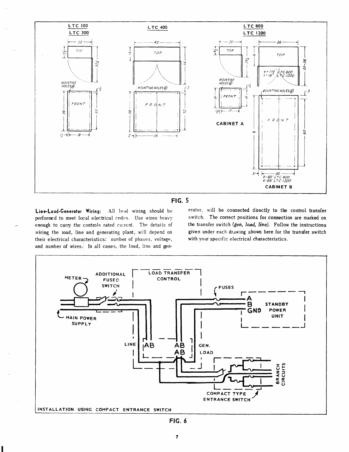
power returns, the control sbould then operate in e normal
manner (except without the time delay). If this happens,
check the relay.
NOTE: The start time delay cannot b tested in lf,is manner.
Whan if is linclsM in tha circait, ff,e slarf-sbp rcIay is
elininated and tho tine delay contacts qntrol lhe plant
directly.
RELAY REPAIR
Except for the transferswitch and transferswitch pilot-relay,
Onan does not recommendrepairing relays. If defective,
replace them. However, relays with dirty contacts can be
cleaned with hard paper or gauze tape soaked in carbon
tetrachloride. U contacts are pitted, replace the relay.
TRANSFER
SWITCH
REPAIR
All transferswitches have replaceable
contacts and coils.
CAUTION: Do not touch the tl.rlnsler
svitch unless notmal
Iine pover is o|f. Se/ lle Operation Se/ector Sc/irdr (what
used) to STOP position or disqnnect statin! batteies
Transler srvircJr
coils are ratedaccordingto voltage. Coils
used at rated voltage (stamped
on coil) should last indefi-
nitely. If magnet
does not close freely (as whendirty) the
coil overheats
and could
burn
up (coils can also burn
from
excessively high or low voltages). To remove
coils see
Table
3.
TABLE
3. COILREMOVAL
Contacls neverrequirecleaning
(or refacing)
for the life of
the equipment. Dis-colored
silver contactsoperate
effi-
ciently. Filing thecontact
facesdestroys
their matingsur-
face.
If contact
points
become
badlyburned
or
pitted,
replace
themas follows:
1. Remove
plastic
hood.
2. Removespringand
washer
frorn
each
contact
guide
post.
3. Lift contactsfrom guidepost. Curvedsilver contact
surfaces
face
inward.
4. Takeout stationary
contacts
by removing
screws
holding
themto
the
transferswitch
olastic
bodv.
Tronslcr SwitchHur: Whena Imd is connected
to the normal
povet source, the switch may be mechanically held which
eliminates hum. When
the transfer switch connects the load
to the (eneratin( plant, the switch is electrically hetd and a
hum condition can occut. Hummay occur in ncchanically-
held switches because of incorrect adjustment of the coil-
disconnect micro-switch. To minimize contact hum,magnet
sealing faces were ground and polished (some switches
include shading coils). Ercessive hum can be caused by
dirt between the magnet sealing faces. Clean them with
cerbon tetrachloride. Use mediunrfine grade emery paper
on ntsted sealing faces. Removeall traces of emergydust.
At some titne, the transfer switch lineside latching mech-
anism may require adjustment. Transfer switch chattering
can be caused by a latching mechanismthat does not lock
the contactsclosed which causesthe mechanism
to pickup
and
drcp
out repeatedly.
Transfer switches featuring mechanically held line con-
tacts or electrically held getterator contacts, operate as
follows:
The line contacts are closed and locked in the following
manner
(see Fig.22). The lineside main coil pulls the
contacts closed. While the contacts ane closing, the
mechanicallatch engages
the contact control md and locks
thecontacts
closcri. At the
sametime,
an
arm
on themech-
anical latch actuates
the coil disconnectswitch (micro-
switch)
which
opens
the
main
coil circuit. The line
contacts
are now closed
and lcnked
in place and power
is removed
from
the main
coil simultaneously.Removal
of power
fmm
the ma-rn
coil eliminates
anyelectrical
noise
(hum)
fromthe
transfer switch. To open the line contacts,
the latching
coiI must be energized which disconnects the latching
mechanism
allowingthe
linc
contacts
to
open.
The latching mechanismand the coil disconnect
switch
mustbe adfusted
to openthe main
circuit just as the con-
tacts reachthe closed
position. tf the maincoil circuit
is not
broken,
hummayresult. tf thecoil disconnect
switch
opens the coil circuit before
the contacts are seated,the
contacts will chatter. Each transferswitch has several
electrical interlock switches (see
Fig. 21) which are oper-
ated
by the mechanicalmovements
of the line and
generator
contact
control
rods.
ADJUSTING
MECHANICALLYHELDSWITCHES
To adjust the latching mechanism
for positive locking,
loosen
the
locking
screws
whichsecure
thelatching
brackets.
Adjust
the bracket
for l,/16" clearancebetween
the latching
lever and the contact operating rod when the main coil
armature
is fully seated(Fig. 20). On units with roll pins
locking
the latching
coil, remove
the noll
pins to makethe
adjustment. After the adjustment
is complete,
drill new
holesand
installnew
roll
pins.
MECHANICALLY HELD S}VITCH 2OG'4OO
A1.IP
(FIG. 22)
l. llisconnect coil lead wlres.
2. Remove cap screws (4) mountlng thc coll and stationary
magnet assembly to the cas
e.
3. Pull out assembly
4. Remove coil from magnet assembly.
MECHANICALLY HELO SWITCH IOOAMP (FIG. 2I)
l. Disconnect the coil lead wires.
2. Snap off the hairpln-shaped retainlng clips holding the
control rod and slide out the control rod.
3. Slide out the stationar/ armature
and coll assembly.
4. Remove the coil from the stationary armature.
t7
This manual suits for next models
6
Table of contents