Onbon OVP-M2 User manual

OVP-M2
User Manual
OVP-M2 user manual

Statement
Any companies or privates cannot copy, transcribe or translate part or whole content of this file
without our written permission. And cannot use it on any business or benefit filed with any forms.
The specifications and information which are mentioned on the file is for reference only, if there’s
update, we will not inform you. This file is only for guidance, and all information will not be for any
promises.

CATOLOG
Instruction............................................................................................................................................................ 2
Characteristics.................................................................................................................................................... 2
Hardware instruction..................................................................................................................................................3
Front panel picture............................................................................................................................................. 3
Backside panel picture...................................................................................................................................... 4
Connect the device.................................................................................................................................................... 5
Port connection picture..................................................................................................................................... 6
MENU INSTRUCTION.............................................................................................................................................. 6
Output menu....................................................................................................................................................... 9
image effect menu............................................................................................................................................10
Image crop menu............................................................................................................................................. 11
Image layout menu.......................................................................................................................................... 12
Mode save menu..............................................................................................................................................13
Advanced setting menu.................................................................................................................................. 14
Guide mode.......................................................................................................................................................16
User setting............................................................................................................................................................... 17
Part display........................................................................................................................................................17
Switch ,review mode........................................................................................................................................18
FAQ.............................................................................................................................................................................19

Brief instructions
Safety Notes
Input voltage is 220V, voltage range is from 100V-240V, please make sure the quality of the power
supply of OVP series.
Please make sure that all the power supply cables are plugged off when you want to connect or plug
off any signal or controlling cables.
Please make sure that all the power supply cables and signal cables are plugged off when you need
to put in or take off the hardware equipment.
Please take off the power supply of LED video processor before you do any hardware operations,
and ESD by touching the ground.
Please make sure the environment is clean, dry and ventilated when you use this product, also, do
not put this product to a high temperature and wet environment.
This product is electronic products, please keep away from fire, water source and
flammable&combustible products.
There’s high pressure components in this products, please do not open the box and repair it by
yourself.
Turn off the power supply immediately when you find smoking, peculiar smell or something unusual.
And contact with us soon.
Function Introduction

Instruction
OVP-M2 is a type of high performance video processor .it is specially developed for controlling large
full color led display screen ,Using professional video image processing chip, internal 12-bit digital
processing, the image is clearer and more colorful. It can be configured with LedshowTV software,
convenient to configure multiple format video input parameters. Satisfy you by it’s best image quality
and flexible image controlling. And better to use in projects, smaller advertising screen, smaller meeting
room, etc.
Advanced interlacing image self-adopt processing technique (DCDI), as to get a more smooth
display. It’s more clear and smooth for interlacing PAL/NTSC video; It’s more abundant for 1080i signal.
Automatic identical engine of input signal source, users can edit DVI input resolution format, as to
make it the same with LED screen resolution. The output image will be perfect, without compression and
stretch.
Zoom in and out technique, and support 8 output resolutions, users can also customize the output
resolution. The maximum output width pixels is 3840 and the maximum output height pixels is 1920.
Also, you can use the fixed standard output resolution, then, zoom in or out according to your
requirements.
Support seamless switch and fade in/fade out switch ,dual image display between different signage
source.
Many kinds of video image input ports: 2×CV、1×VGA、1×DVI、1×HDMI,1×SDI support full high
definition signal input, and can connect with many audio, video equipment.
Characteristics
Support intelligent guidance for quick setup
Support 8 kinds of mode ,switch by one button
Adopt 10+ Bit Faroudja® DCDI video processing
Adopt Faroudja® Real Color® processing
Support frame synchronous technique, there will be no delay and dislocation
Support brightness,contrast ratio ,enhance the image display effect
Users can do PIP or PBP in any position

Cut and Fade function of input signal source
Support customized DVI input resolution, as to be the same with LED screen resolution, and to
display point to point
Support customized output resolution, the maximum width pixel is 3840 and the maximum height
pixel is 1920 for single device
24 hours high and low temperature ON/OFF, burn-in test, high performance and stable
Hardware instruction
Front panel picture
Interface instruction
1
power
Power on/off
2
MENU area
There are one knob, one button[OK]and one button[ ]
knob:For menu operation, rotate clockwise or counterclockwise,
select menu items or adjust parameters.
Light press [OK]button:indicates that the main menu appears in the
initial state, and the menu state is to confirm button.
[ ] return button:to return to the previous menu, and return to the
initial state of the menu directly.
○
1
○
2
○
3
○
4

3
FUNCTION
area
There are total 4 buttons:[BRI]button、[PIP]button、[PART]button、
[MODE]button
[BRI]button:brightness adjustment button for output image,change
the value by turning the knob clockwise or
counterclockwise.short press the [OK]button to save
[PIP]button:PIP menu shortcut button.
[PART]button:Interception input image full screen or local display,
initial for full screen display, switch local display.,[PART]button light
on。
[MODE]button:image mode or save the menu shortcut button
4
INPUT area
6 buttons in total:[DVI] button、[HDMI] button、[CV1] button、[CV2]
button、[VGA] button、[EXT] button
[DVI] button:computer digital signal input port selection button
[HDMI]button:digital HD signal input port selection button
[CV1]button:compound video input port 1 selection button.
[CV2] button:compound video input port 2 selection button.
[VGA]button:Computer analog signal input port selection button.
[EXT]button:extend module input port selection button.
Backside panel picture
Power
Input voltage
100-240V~ 50/60Hz
Interface instruction
○
1
○
2
○
3

1
SDI port :SDI Video input port embedded.
SDI LOOP port:extend module SDI input loop out.
COM port:serial port communication port ,connected with computer
port :Analog audio input/output port, when the output is selected input
signal source audio.The input can be external audio, via the sending card to
the LED screen.
2
HDMI port:digital HD signal input port, input video and audio signal.
VGA port:computer analog signal input port, connected to the computer.
DVI port:computer digital signal input port, input video signal.
CV1 port:compound video input signal source 1.
CV2 port:composite video input signal source 2.
3
DVI port :digital HD DVI output port, output video signal, connected with
monitor
LED1/LED2:Gigabit network data transmission, connected with LED screen
receiving card.
Connect the device
Here take the DVI signage as an example:
Network
cable
DVI cable
cable

Port connection picture
MENU INSTRUCTION
OVP-M2 uses a LCD screen to display menu system,users can use the Rotating button and panel
buttons to adjust the parameters.
The flowing will introduce the menu system of OVP-M2 in details according to the button function and the
display content of LCD screen
Button instruction
OVP-M2 have three areas:INPUT、FUNCION、MENU.
INPUT AREA
There are six buttons in this area:[DVI]button、[HDMI]button、[CV1]button、[CV2]button、[VGA]button、
[EXT]button。Users can switch the input signal source by press these buttons, In the initial status of the
menu system, short press button in the area, the main screen input signal source can be switched, if the
Video processor serial
port connect cable
Network
cable

PIP screen is opened, the PIP screen input signal source can be switched.
The system will automatically check the input signal format, if format of the current input signal source is
right ,the button lamp always bright, if there is no signal or the format is not supported, button lamp light
will flicker.
Under the VGA signal input source, continuously press the[VGA] button for three times ,the system will
adjust the white balance to input analog signal automatically and the image that the input image is full
screen and with a brighter edge should be ensured.
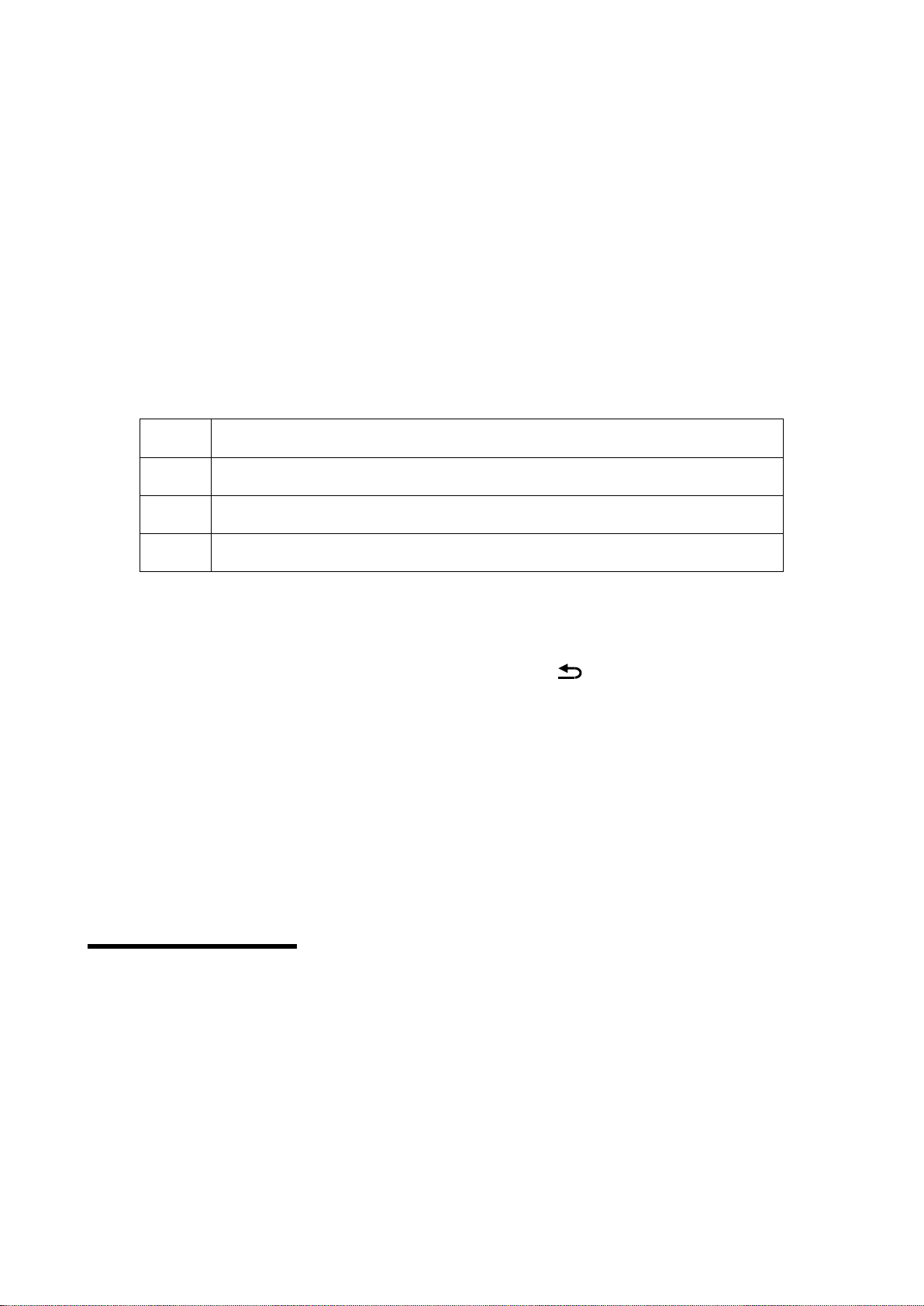
FUNCTION AREA
There are four buttons in this area:[BRI]button、[PIP]button、[SIZE]button、[MODE]button。
BRI
Export the brightness menu, and adjust it by rotating the button, save it
by pressing [OK]
PIP
Turn on or turn off the PIP function, and it will be lighting if the PIP
function is ON
SIZE
Display the full image or part of it. The initiated is full, you can switch to
part (size button will be lighting).
MODE
Export the image mode, use or save. Users need to save the image
more, then, can use.
MENU AREA
This main menu area includes a Rotating button,and a OK button,and a return button, in the system
initial states use the [OK] button enter into the sub menu.press [ ] to return or exit the main menu.
In the In browse mode, counterclockwise the rotating button, the cursor will move up or left ,
clockwise the rotating button, the cursor will move down or right . When the cursor is moved to a project
that needs to be adjusted, press the [OK] button, it will move into the setting mode, then
counterclockwise the rotating button to reduce the current parameter value;clockwise the rotating button
to increase the current parameter value. If the adjustment is completed, press [OK] button to save data.
If users need to return to the last menu, use the return button until it return to the initial state.
Rotation [knob] can not force too fast, otherwise the numerical adjustment is very small, should
rotate at a constant speed.
System initial states
When starting the system, the LCD screen will display the Boot interface. After the start of the
system, the status of the current machine will be displayed on the screen. In the initial state of the
system shows the information in two pages, and the timing transformation is displayed. The starting
menu of the system starts as shown in the following figure:
The detail meaning of above image

A
Title
B
Name of input signal source
LED screen
C
Resolution format of input signal
source
Resolution format of input signal
source,corresponding to the physical resolution
of LED screen
D
Status area, to show you the status of this machine by many icons.
There are 4 icon areas from left to right, and it shows only 3 in original status
Status of “PART” ;
2. Status of PIP ;
3.Unlocking the keys on board ;
4. Brightness of output image
In initial status, the fourth line of the LCD screen will show current machine status ,the means of the
icon please refer to the following:
Icon
Area
Name
Explanation of all icons:
1
Part off
”PART” is OFF, it will show the whole image in LED
screen
1
Part on
”PART” is ON, it will show the part of the image
2
PIP off
“PIP” is OFF
2
PIP ON
“PIP” is ON
3
Lock off
Button lock is OFF, users can set system
parameters according to the key, and you can turn ON
the button lock in “advanced” of main menu
3
Lock on
Button lock is ON, users cannot do any settings by
key, and you can turn OFF the button lock in
“advanced” of main menu
4
Brightness
Image brightness (BRI)

Main menu
In the initial status,press [OK]button to enter into main screen.the main screen as the follows
The main menu includes the following functions:
Output setting---output resolution ratio of system,LED screen display size,LED screen starting
position
Image effect---Brightness,contrast,saturation and dynamic contrast
Crop image---Open or close Crop、Crop size、Crop Starting position
Graphic layout---main graphic,PIP ,graphic& text overlay
Mode save--- save the current system parameters to the application scene mode
Advanced setting---language selection ,go to the guidance ,input the resolustion ,hot bakup,
VGA setting ,Seamless switching、ADC correction、key button,OSD menu setting 、voice setting ,factory
reset
Output menu
There are four parameters:LED screen parameters、sending card parameters、output resolution、
test picture.
LED screen parameters can adjust the LED screen width、LED screen height、Refresh rate。
Image output
LED screen parameters →
sending card parameters →
Output resolution customized
Test picture →
LED screen parameters
LED screen width 1920
LED screen height 1080
Refresh rate 60

LED screen parameters:set the system output resolution format, in real application,we suggest select
the same resolution with the LED screen.
LED screen width:range from 320-3840,set the LED screen horizontal width
LED screen height:range from 240-1920,set the LED screen vertical height.
Refresh rate:range from 24-60Hz,set the LED screen Refresh rate,we suggest 60Hz.
Mark :restart the device after modify the LED screen parameters ,the system reserved mode will
be cleaned up.
Sending card parameters interface can adjust the network port 1parameters、Network port
2parameters、Refresh rate,used for set Network port display image size and starting position.
Network port 1 parameter:
Network port 1 width:range from 0-2048,set LED1 port image horizontal width。
Network port 1 height:range from 0-1024,set LED1 port image vertical height。
Network port 1 starting X:range from 0-2048,set LED1 port image horizontal starting position。
Network port 1 starting Y:range from 0-1024,set LED1 port image vertical starting position。
Network port 2 parameters:
Network port 2 width:range from 0-2048,set LED2 port image horizontal width。
Network port 2 height:range from 0-1024,set LED2 port image vertical height。
Network port 2 starting X:range from 0-2048,set LED2 port image horizontal starting position。
Network port 2 starting Y:range from 0-1024,set LED2port image vertical starting position。
Refresh rate:range from 24-60Hz,set LED screen refresh rate,we suggest 60Hz.
Output resolution:
contain 15 kinds of fixed resolution format and 1 “user customized”customized” option
parameters and“LED screen parameters”setting 。
Test diagrams:there are 6 test diagrams for LED screen testing.The test diagram requires an
out-of-sync clock, so it is only valid for the DVI/HDMI/VGA input source.When the "normal display" is
selected, the test diagram is closed.In the current signal source, a valid input signal must be received,
and the test diagram has output. Otherwise, there is no output.If the current signal source is DVI, the DVI
port input output is connected, and this function can be realized without external input signal.
image effect menu
sending card parameters
Network port 1 parameters →
Network port 2 parameters →
Refresh rate 60

image effect interface can adjust the brightness、contrast、saturation、dynamic contrast and color
temperature
Brightness:range from 0-100。
contrast:range from 0-100。
saturation:range from 0-100。
Dynamic contrast:range from 0-4,0 is close ,1 is default value,not valid to the input VGA signage
source.
Color temperature parameters:
Color temperature customized:red color adjust range from 0-100。
Blue color adjust range from 0-100。
Green color adjust range from 0-100。
Color temperature type:warm ", "natural" and "cold", "custom" four kinds of options.
Image crop menu
Image crop interface can adjust the crop window、crop width、crop height、horizontal starting and
vertical starting
Crop window:Crop window is opened or closed ,default is closed, Choose the corresponding input
source by INPUT button ,and it is limited to open Crop,check from the below list for details.
Image effect
Brightness 50
Contrast 50
Saturation 48
Dynamic contrast 1
Color temperature →
Color temperature
Customized →
Type warm
Image crop
Crop window close
Crop width 1024
Crop height 768
Horizontal starting 0
Vertical starting 0

Crop width:minimum is 128,maximum is “the width of present output resolution ratio”.
Crop height :minimum is 128,maximum is “the height of present output resolution ratio”.
Crop horizontal start:minimum is 0,maximum is the difference of“width of present output resolution
ratio”and“Crop width”
Crop vertical start:minimum is 0,maximum is the difference of“height of present output resolution
ratio”and“Crop height”
Image layout menu
There are two interface :main image mode and PIP mode
Main image parameters:
Main image width:the minimum value is 62,maximum value is the width of LED screen(example:
1024 in the 1024x768@60Hz )
Main image height:
the minimum value is 48,
the maximum value is “LED screen height”
(example:
768 in the 1024x768@60Hz).
horizontal starting :the minimum value is 0,the maximum value is “LED screen width”and“image
width”difference value
vertical starting :the minimum value is 0,the maximum value is “LED screen height” and “main
image height”difference value
PIP mode type:PIP mode and graphic overlay mode
PIP mode parameters:
PIP window:PIP window is opened or closed ,default is closed, Choose the corresponding input source
by INPUT button ,and it is limited to open PIP,check from the below list for details.
PIP width:minimum is 128,maximum is “the width of present output resolution ratio”.
PIP height :minimum is 128,maximum is “the height of present output resolution ratio”.
Main image
Main image width 1024
Main image height 768
Horizontal starting 0
Vertical starting 0
PIP MODE
PIP window close
PIP width 320
PIP height 240
PIP horizontal start 0
PIP vertical start 0

PIP horizontal start:minimum is 0,maximum is the difference of“width of present output resolution
ratio”and“PIP width”
PIP vertical start:minimum is 0,maximum is the difference of“height of present output resolution
ratio”and“PIP height”
Graphic &text overlay parameters:
Graphic &text overlay:Optional turn on or off, default to close.After opening, press the front panel
button of input area to select the corresponding text input source.There are three types of text
background colors: black, white, and blue.
M2 Double image input conflict limit
Chane1 2
Chane1 1
CV1
CV2
VGA
DVI
HDMI
EXT.
CV1
√
X
√
√
√
√
CV2
X
√
√
√
√
√
VGA
√
√
√
√
√
√
DVI
√
√
√
√
X
√
HDMI
√
√
√
X
√
√
EXT.
√
√
√
√
√
√
Screen 1 is the main screen ,Screen 2 is the sub-screen,if users did not handle interfaced ,you can
exchange the input source 1 of screen 2
When select the input source,if the screen 1 and screen 2 conflict for the port,then can’t select the
screen 2 port ,and prompt the “signage source conflict”
Mode save menu
As shown in the picture :
Mode save :the system provide 8 kinds of save modes,users can save the current system setting to 1
to 8.
Graphic&text overlay close
text input source HDMI
Text background color blue

8 kinds of save mode:main screen input signal source, led screen width and height,and start
location,PIP signal source,PIP width and height,start location ,Image brightness, image contrast, image
saturation
Advanced setting menu
Advance set menu options is shown as bellow:
Language:The system support Chinese and English
Navigation mode:guide the user to the navigation mode ,fast light the LED screen ,finish system
parameters setting.
Input resolution:provide the DVI/HDMI input signage source EDID edit function
There are two kind of EDID: fixed EDID and custom EDID. That is: set the recommended resolution
of the input DVI signal source, graphics card of computer automatically read the EDID of the input DVI
port of the device, and output the recommended
Fixed EDID
800×600@60Hz、1024×768@60Hz、1280×1024@60Hz、
1366×768@60Hz 、1440×900@60Hz、1600×1200@60Hz、
1920×1080p@60Hz、1920×1200@60Hz、2048×1152@60Hz、
2304×1024@60Hz、2560×816@60Hz、3840×630@60Hz、
1080×1920@60Hz、1200×1600@60Hz、1536×1536@60Hz
Custom EDID
Input width:customized resolution of horizontal pixels
Input height:customized resolution of vertical pixels
Advanced options
1.Language Chinese
2.Into navigation →
3.Input resolution →
4.Hot backup →
5.VGA Automatic adjustment →
6.ADC Correction →
7.seamless switching gradual change
8.key lock Close
9.OSD menu setting →
10.Set volume 15
11.Reset to factory setting →

Input frequency: refresh rate of custom resolution
In order to make the resolution of input image and output image consistent and the user can manually
input DVI resolution format. The parameters (input width, input height) are set according to the
resolution.physical resolution of LED screen. The input width range is 320-3840, the input height range
is 240-1920, the output field frequency range is 24-60 Hz, and the total control area is not more than 2.6
million pixels.
Hot backup:The input signal hot backup function, that is, after the current input signal is lost, the
processor automatically switches to the backup input signal to avoid the output image interruption
caused by the source failure.CV1/CV2 is a group, DVI/HDMI is a group.
VGA automatically correction:automatic to correct the VGA input image position and phase position.
ADC calibration:Analog signal white balance correction,click [OK]button to correct the white balance to
input analog signal automatically(CV1,CV2 VGA )input signal source need to be calibrated individually
for each port.).
Note: the processor has done white balance correction for standard signal source before
leaving the factory. Please use this setting carefully.
Seamless switching: used to set the switching effect between signal sources. Includes :fade in and fade
out.
Key lock:panel lock function,when open the key lock function,then the device panel key will be not valid
to work no matter press any key.
OSD menu setting :adjust the display starting position on the the controller remote menu
Voice volume setting:only input signage source to HDMI when the voice open or close ,Adjust range
0-30,adjust HDMI or SDI audio volume
Factory reset:System initialization settings, The system parameters will be reset to factory
value.Usually we do not suggest users to do it.
Device user guiding
Before to use the guiding mode ,please set the system output resolution first.if there is no saved
mode , the system will lead the users to the guiding mode in order to use the device quickly.There are 3
steps for the guiding mode
Step 1:Power on,start the machine
Step 2:Choice input signal source
Step 3:set the screen width and height
In guide setting status,press[ ] to return to the previous step to modify the parameter

Guide mode
When the machine is power on,it will show the following interface
Press [OK] button to run into the “input” interface,as shown in picture
Switch the signage source by press the front panel signage selection key ,short press the [OK]
button to save the data and enter the "LED screen parameters setting" interface,as shown in picture
Rotate the[OK]button to modify parameters short press [OK]button to set the“LED screen width”
or“LED screen height”

Adjust the parameters by rotate the OK button ,make the value bigger or smaller ,then return to the
current menu and select” effective”to save data then restart the device.
User setting
Guiding the users to quickly use the machine,the following will show you the common functions of
the video processor:Partly display ,mode save, mode cover,clear mode,switch mode,check saved mode
parameter etc.
Part display
Part display is to show the full led display window, users can switch to display the full desktop of
the computer at any time
If use crop to display the image ,the default crop width and height is the same as the Led
screen.the Crop horizontal and vertical start from (0,0)
Part display full screen display
To use the part function ,the input signal should be HMDI and DVI, If the current signal input source
is HDMI, when open part, the part display will be banded to HDMI,if the current signal input source is
not HDMI, the part display will be banded to DVI.
Table of contents
Other Onbon Media Converter manuals