
www.one-lux.com 4
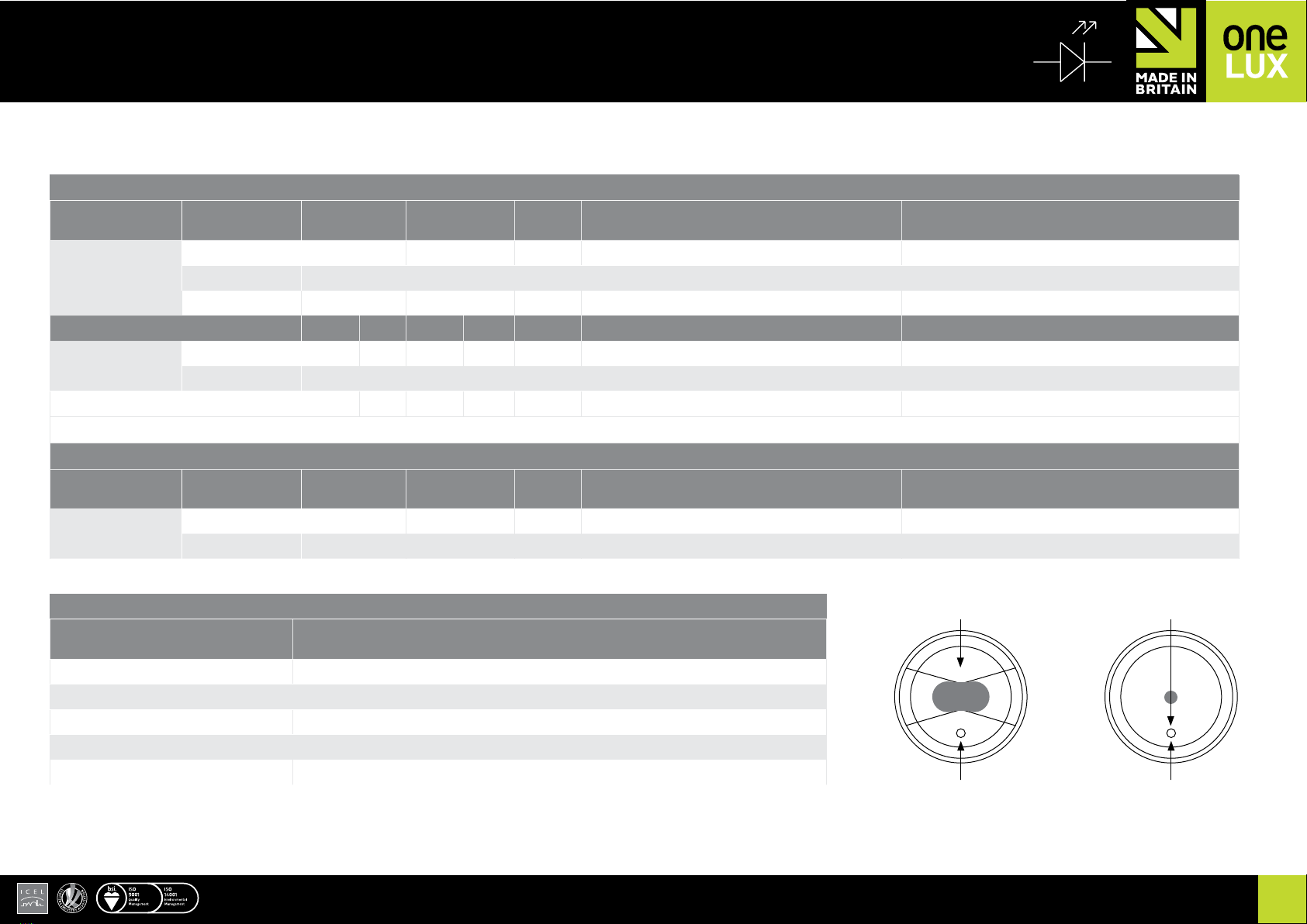
Push-to-test area (Re-
cessed Ceiling Lamp
head only)
INSTALLATION (continued)
EMERGENCY | ONE-LEDTM
SOLO SURFACETM | NON MAINTAINED LED EMERGENCY LUMINAIRE
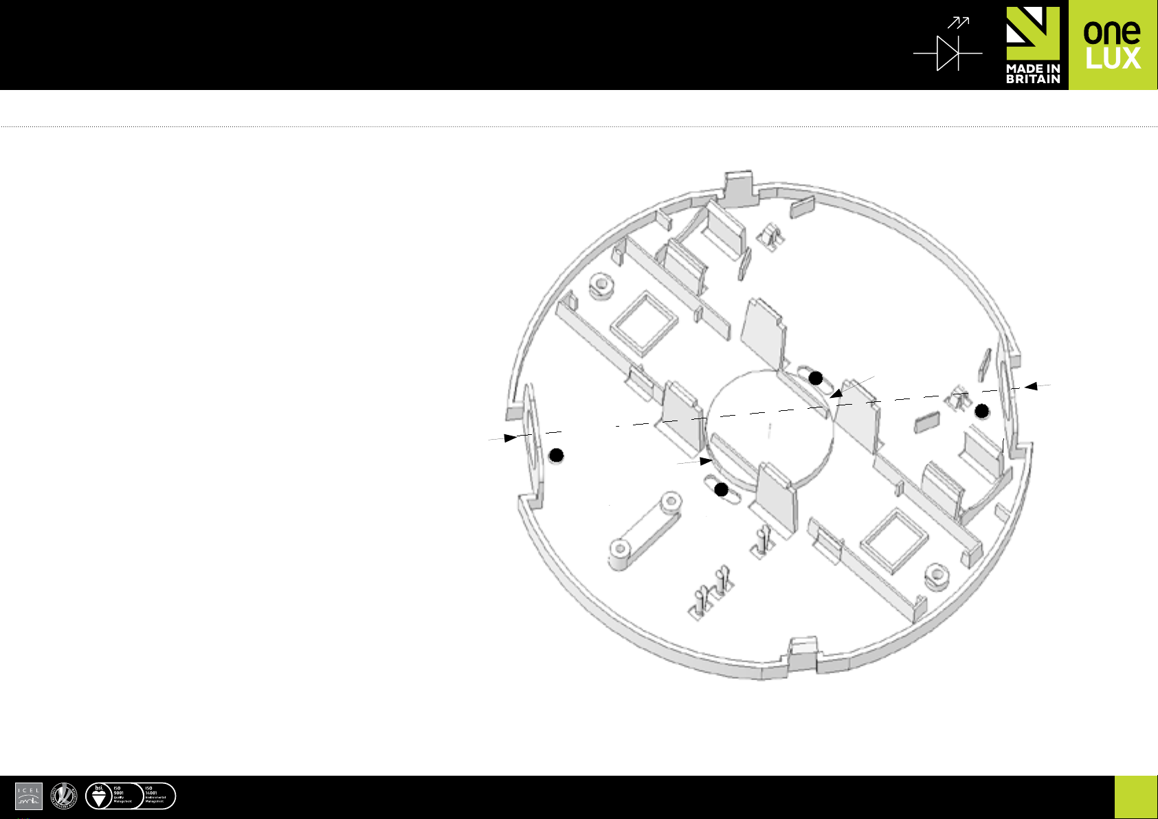
Wiring
When xed in position, prepare the supply cables with a strip length of
6mm (10mm maximum). Min/max Conductor sizes: 0.5 - 2.5 mm2.
Incoming mains connections should be made to push-wire terminals
marked ‘L’, ‘E’ and ‘N’. (and DALI bus to terminals marked ‘DA’ for /DST
versions). Please note the Earth terminal is only provided for the purpose
of terminating the incoming cable(s) and is not required for function or
safety. This product requires a permanent supply (via test key switch where
required). Once the supply connections are made, ensure the cord restraint
is xed in position as required.
Function test and commissioning
Note: This luminaire will only operate the white LED upon mains supply
failure from the internal battery supply; it cannot be operated as a standard
light source.
After installation, the red battery lead should be connected to the battery
positive and the mains supply turned on. The green indicator LED should
now be visible on the lamp head’s front bezel, showing the battery is
connected and being charged.
When the mains supply is turned off, the white LED will illuminate in
emergency mode. Reinstate the mains power, or disconnect the battery to
stop emergency operation.
Once the luminaire is ready for commissioning the battery positive should
be connected and the front cover tted into position.
The mains supply can then be instated and must remain un-interrupted for
a minimum of 24 hours for the luminaire to fully charge its internal battery.
After 24 hours, the mains supply should then be turned off and the
luminaire checked for a minimum of 3-hours duration. If successful the label
on the battery must be initialled and dated by the commissioning engineer.
Emergency Lighting ‘standard’ or ‘manual’ Test
The following minimum inspections and tests should be carried out:
Monthly
Switch off the mains power supply to the luminaire. Inspect the emergency
Switch off the mains power supply to the luminaire. Leave the unit to run for
the rated period (e.g. three hours). The light should remain operable from
the battery for the whole period. Please be aware that further inspection /
testing may be required, e.g. by risk assessment / local legislation.
Maintenance
There are no user serviceable parts within the product. The battery pack
must be replaced when the 3 hour duration is no longer achieved.
The battery is not considered user-replaceable and must be referred to
a competent engineer. Please contact one-LUX for technical support or
suitable replacement parts.
Front cover removal: If the front cover needs to be removed after tting
place, carefully press a narrow blade screwdriver through the small slots
located at opposite sides of cover’s side walls whilst pulling that side of the
cover away from the base.
Batteries and Disposal
The battery has a designed service life of 4 years and must be replaced in
a timely manner to ensure the integrity of the emergency lighting system
is maintained. In any case, the battery should be replaced with when it no
longer provides the rated duration (3 hours).
One-LUX are committed to full its obligations as a producer of batteries
used in emergency lighting applications. End-of-life batteries may either
be returned to us at the customers cost and arrangements will be made
to ensure their correct disposal. Alternatively it may be more convenient
for the customer to deliver end-of-life batteries to site(s) of authorized
treatment facilities at their cost and it will be ensured that they are accepted
back and subsequently treated to the standard required by the regulations.
Disclaimers
This product and its associated accessories have been designed
and manufactured to comply with the requirements of EN60598-
2-22 and required additional standards. Operation beyond the
parameters specied in this document and the associated standards
may result in reduced performance and ultimate premature failure,
with the warranty made void. The specier should be aware of the
environment to which this luminaire and components are used and
adhere to its specications. Please contact our Technical department
if you are in any doubt.
The unit provides reinforced insulation between the mains supply
and battery charging circuit and employs self-resetting protection
against short-circuit of battery terminals. Normal charging will
resume automatically once a fault is removed.


