ONKRON G140 User manual

Height adjustment
0 - 690 mm
0" - 27.2"
G140
Max weight
2 x (1 - 8 kg)
2 x (2.2 - 17.6 lbs)
Tilt
-35° ~ +35°
VESA
75 x 75
100 x 100 mm
EN USER GUIDE
RU
РУКОВОДСТВО ПОЛЬЗОВАТЕЛЯ
ES
GUÍA DEL USUARIO
IT
GUIDA UTENTE
DE
BENUTZERHANDBUCH
FR
MODE D'EMPLOI
Dual monitor desk mount with gas liſt system
Tischhalterung für zwei Monitore mit Gasliſt-System
Support de bureau à ressort à gaz pour deux écrans
Supporto per due monitor da scrivania con molla a gas
Soporte de escritorio con resorte de gas para dos monitores
Настольный кронштейн для двух мониторов с системой газлифт
Газлифт жүйесі бар екі мониторларға арналған үстел кронштейні
Orientation
360°
Swivel
180°
Screen size
13"- 32"
Arm extends
0 - 534 mm
0 - 21"
KZ
ПАЙДАЛАНУШЫ НҰСҚАУЛЫҒЫ

2
Thank you for choosing us!
We hope you are happy with your purchase. If you enjoy our product, please leave your
review.
If you have any questions or issues, contact us anytime and we will help you as soon
as possible:
USA: [email protected] / +13159682278
Europe: [email protected] / +494029996807
Russia: support@onkron.ru / +78007772176
Read the entire manual before you start assembly and installation. If you have any
questions about the assembly and operation of the bracket, please contact our service
department.
CAUTION
Using the product with devices that exceed allowed weight limit, improper assembly
and installation, including overtightening mounting screws, may lead to failure of your
devices and the product itself, and also cause personal injuries.
•Рroduct must be assembled as specified in the following assembly instructions.
Improper installation may result in damage or serious personal injuries.
• Safety gear and proper tools must be used. This product should be installed only
by professionals.
• Make sure that working surface will safely support combined weight of the
equipment and all attached hardware and components.
• Use mounting screws provided in the kit and DO NOT OVERTIGHTEN any screws
during assembly of the product.
• This product contains small items that may cause choking if swallowed. Keep
these items away from children.
• Using the product improperly could lead to product failure and personal injuries.
• Before mounting a screen make sure it meets all requirements of the product.
Pay attention to VESA patterns, supported screen weight and diagonal.
• Mounting an unsupported screen could lead to product failure and personal
injuries.
IMPORTANT
Make sure you have received all parts according to the component checklist BEFORE
the installation. If any parts are missing or faulty, contact your local distributor for a
replacement.
WARRANTY
Not under mandatory certification. Unlimited lifespan. 5 YEARS WARRANTY.
MAINTENANCE
Check your product is safe to use at regular intervals (at least every three month).
Қазақ
Русский
Español
Italiano
Français
Deutsche
English

3
Assembly Kit
Firstly unpack all components and make sure that you have all necessary
parts. If you miss any parts, please contact our support team. Check the
list:
M4x12 (x8)
M-A
M4x16 (x8)
M-B M6x12 (x8)
M-C
M6x16 (x8)
M-D
D6 (x8)
M-E M-F (x8)
6mm (x1)
L
4mm (x1)
K
(x1)
J
(x1)
I
(x3)
H
(2x)
G
(x1)
F
(x1)
B
(x1)
C
(x2)
D
(x1)
E
(x2)
A
MOUNTING KIT FOR SCREEN:
Қазақ
Русский
Español
Italiano
Français
Deutsche
English

4
1. Choose how you want to install the desk mount:
a) C-Clamp installation on the edge of the desk:
• Take the C-Clamp (B), it consists of two details connected with two screws. If
your desk thickness is 1.3" – 3.1" (35~80 mm) use two lower holes, if 0.4" –
1.77" (10~45 mm) use two upper holes. Key (L) may be used.
• Put plastic cover (C) onto C-Clamp (B), as shown. Attach the tube (E) to the C-
Clamp (B) using three screws (H). Key (K) is needed.
• Install the whole construction onto the table and tighten the clamp, by
spinning the knob. Key (L) may be used. Make sure it is securely fixed on the
table.
or
C
B
C
B
E
H
K
L
35-80 mm
1.3" -3.1"
10-45 mm
0.4" -1.77"
L
Қазақ
Русский
Español
Italiano
Français
Deutsche
English

5
b) Installation with a grommet hole in the desk:
• Firstly disassemble C-Clamp (B) as shown on the picture. Attach part (J) to
the tube (E) using one screw (H). Plastic cover (C) must be installed too. Put
the clamp screw (from disassembled part B) through part (I) and through the
hole in the desk, and then twist it in the tube (E), by spinning the knob.
• Acceptable hole diameter 0.4" – 0.78"(10-20 mm). Key (L) may be used. Make
sure it is securely fixed on the table.
J
I
H
L
0.4"-2.95"
10-75mm
0.4" – 0.78"
Ø10-20 mm
E
ATTENTION: min desktop thickness = 0.4"(10 mm)
max desktop thickness = 2.95"(75 mm)
ATTENTION: min hole diameter = 0.4"(10 mm)
max hole diameter = 0.78"(20 mm)
L
C
Қазақ
Русский
Español
Italiano
Français
Deutsche
English

6
D
UP
3. VESA panel installation
•Attach VESA-panels (D) to your screens, by using suitable screws (M-A),
(M-C) and washers (M-E). You may use the key (L). Make sure VESA panels are
securely fixed. Look carefully at the picture below:
M-A
M-C
M-E
L
2. Mounting arm assembly
•Put cable holder (F) on the tube (E). Install mounting arm (A) on the tube (E) at
the desired height and tighten screws using key (L).
F
L
A
A
E
Қазақ
Русский
Español
Italiano
Français
Deutsche
English

7
4. Screen mounting
•Hang your screen onto the mounting arm (A). Fix VESA plate (D) with
screw (G).
UP
M-B
M-D
M-E
M-F
L
•Other screws (M-B), (M-D), washers (M-E) and spacers (M-F) can be
used as required. You may use the key (L). Make sure VESA panels
are securely fixed. Look carefully at the picture below:
G
Қазақ
Русский
Español
Italiano
Français
Deutsche
English

8
5.1 Take off plastic panels from the lower part
of the arm by sliding them away from the tube
(E).
5. Cable management
5.3 Install plastic panels back on their
places by sliding them towards the tube (E).
Keep in mind that cables should hang down a
bit to provide easy movement of the arm.
5.2 Lay cables through the top parts of the arm (A).
6. Adjustment of the gas-liſt system
6.1 Adjust tension of the gas-liſt system in each arm to match weight of your
screens. Turn the key to (+) for heaver screens, or to (-) for lighter ones. Move the
screen up and down, until it is stable in any position you choose. The arm must be
adjusted for each screen individually. If the arm is falling down – turn to (+), if the
arm is moving up – turn to (-).
+
-+
-
(-) (+)
5.3
5.2
5.1
6.1
E
E
Қазақ
Русский
Español
Italiano
Français
Deutsche
English

9
7. Key holder installation
•You can use plastic key-holder
(F) on the tube (E) to keep
keys (L), (K).
L
K
F
E
6.2 Adjust tilt angle if necessary. You may use key (L).
DO NOT OVERTIGHTEN! Overtightening may cause damage to your
screens and/or the mount.
L
L
6.1
6.2
Қазақ
Русский
Español
Italiano
Français
Deutsche
English

10
Danke, dass Sie uns gewählt haben!
Wir hoffen, dass Sie mit dem Kauf zufrieden sind. Wenn Sie unser Produkt mögen,
lassen Sie bitte Ihr Feedback.
Wenn Sie irgendwelche Fragen oder Probleme haben, dann können Sie uns jederzeit
kontaktieren und wir werden Ihnen helfen:
USA: [email protected] / +13159682278
Europa: [email protected] / +494029996807
Russland: support@onkron.ru / +78007772176
Lesen Sie diese vollständige Anleitung, bevor Sie mit der Montage und Installation
beginnen. Wenn Sie Fragen zu Montage oder Warnungen haben, wenden Sie sich bitte
an Ihren lokalen Händler.
ACHTUNG
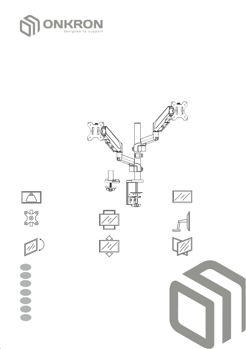
• Die Verwendung des Produkts mit Geräten, die das zulässige Gewicht
überschreiten, kann zu einem instabilen Betrieb des Produkts, seinem
vollständigen Ausfall und zu Verletzungen geführt werden.
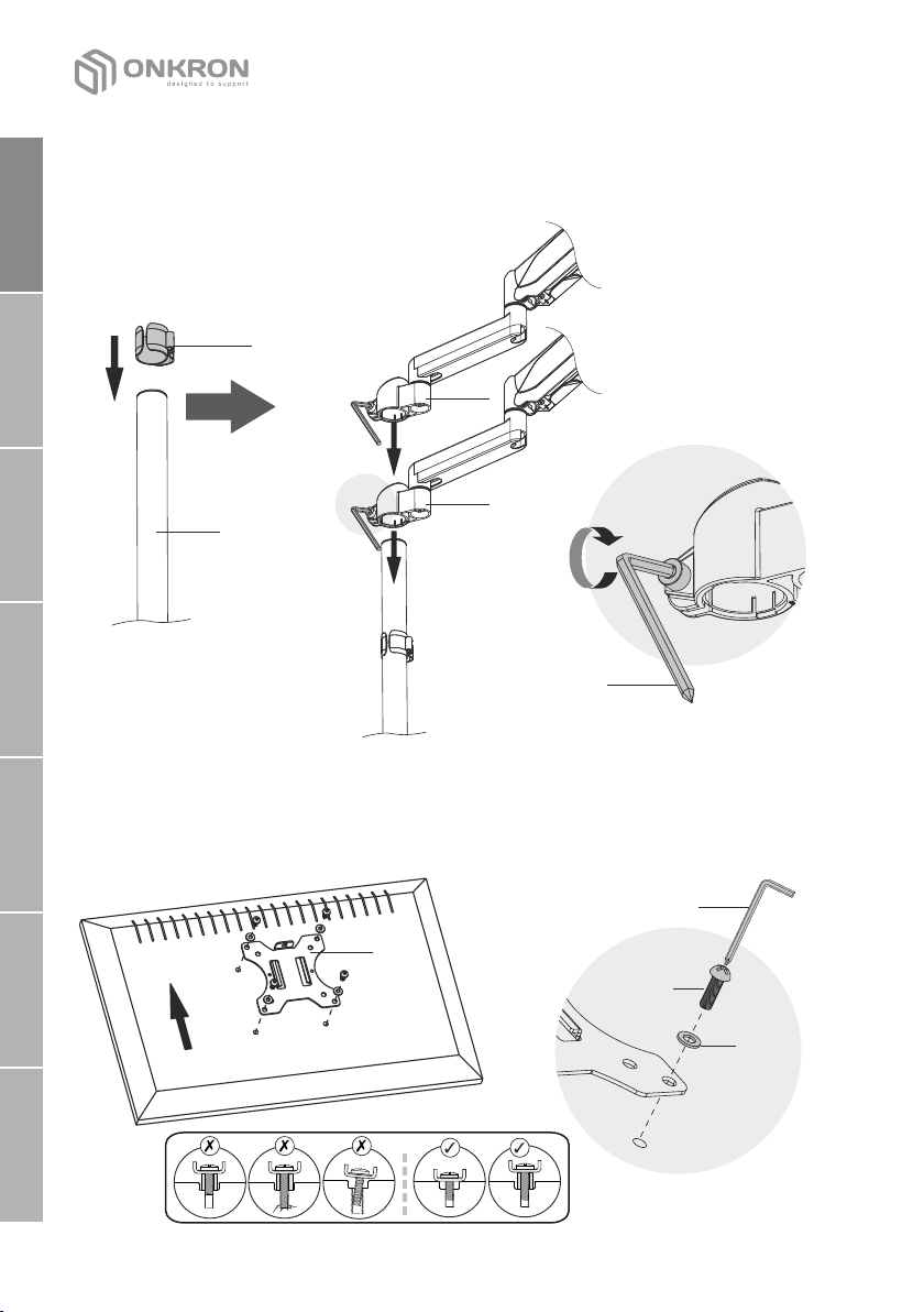
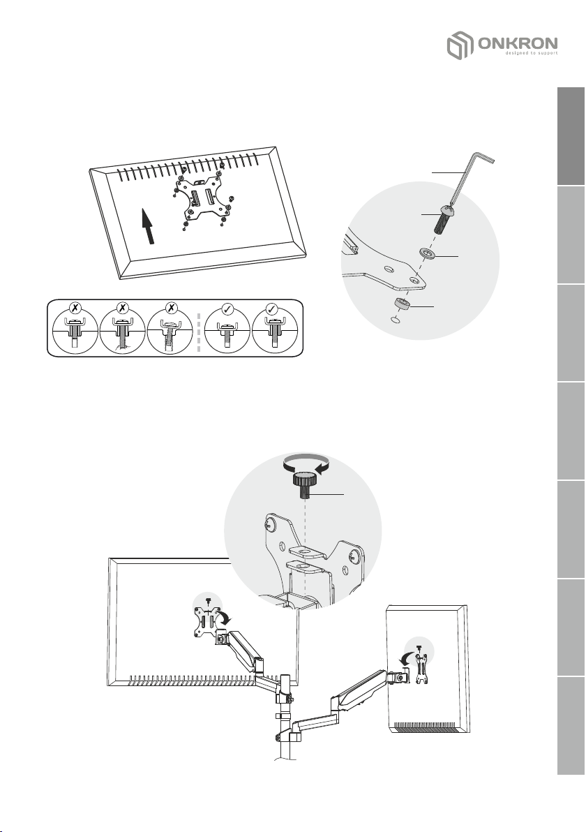
• Das Produkt muss gemäß dieser Anleitung zusammengebaut werden. Eine falsche
Installation kann die Gesundheit des Benutzers erheblich beeinträchtigen.
• Es ist notwendig, persönliche Schutzausrüstung und die richtigen Werkzeuge zu
verwenden. Das Produkt muss von einem Fachmann montiert und installiert
werden.
• Stellen Sie sicher, dass die Arbeitsfläche das Gesamtgewicht des verwendeten
Produkts, des verwendeten Geräts und aller optionalen Komponenten tragen
kann.
• Verwenden Sie die Schrauben aus dem mitgelieferten Kit und ZIEHEN Sie sie nicht
während der Montage und Installation.
• Das Produkt enthält kleine Teile, die beim Verschlucken zu Erstickungsgefahr
führen können. Bewahren Sie Sie außerhalb der Reichweite von Kindern auf.
• Unsachgemäße Verwendung des Produkts kann zu Produktschäden und
Verletzungen geführt werden.
• Stellen Sie sicher, dass dieses Modell vom Produkt unterstützt wird, bevor Sie
den Bildschirm installieren. Überprüfen Sie die VESA-Normen, das Gewicht des
Bildschirms und seine Diagonale.
• Die Installation eines nicht unterstützten Bildschirms kann zu Produktschäden
und Verletzungen geführt werden.
WICHTIG
Stellen Sie vor Beginn der Montage sicher, dass Sie alle für die Montage erforderlichen
Teile erhalten haben. Überprüfen Sie die Stückliste. Wenn die Teile fehlen oder defekt
sind, wenden Sie sich bitte an Ihren örtlichen Händler.
BEDIENUNG
Überprüfen Sie das Produkt regelmäßig auf Sicherheit (mindestens einmal pro drei
Monate).
GARANTIE
Braucht nicht Pflichtzertifizierung. Lebensdauer ist unbergrenzt. 5 JAHRE GARANTIE.
Қазақ
Русский
Español
Italiano
Français
Deutsche
English

11
BAUSATZ
Entpacken Sie zuerst alle Komponenten und stellen Sie sicher, dass Sie
alle notwendigen Teile haben. Wenn die Details nicht ausreichen,
kontaktieren Sie uns bitte und wir senden Sie Ihnen zu. Überprüfen Sie
bitte die Stückliste:
ZUSAMMENSETZUNG DER BEFESTIGUNGSELEMENTE
FÜR DIE BEFESTIGUNG AM FERNSEHER
M4x12 (x8)
M-A
M4x16 (x8)
M-B M6x12 (x8)
M-C
M6x16 (x8)
M-D
D6 (x8)
M-E M-F (x8)
6mm (x1)
L
4mm (x1)
K
(x1)
J
(x1)
I
(x3)
H
(2x)
G
(x1)
F
(x1)
B
(x1)
C
(x2)
D
(x1)
E
(x2)
A
Қазақ
Русский
Español
Italiano
Français
Deutsche
English

12
1. Wählen Sie die Installationsmethode für die Halterung:
a) Installation an der Tischkante mit einer Klammer:
• Nehmen Sie die Klammer (B), sie besteht aus zwei Teilen, die mit zwei Schrauben
befestigt sind. Wenn die Dicke Ihres Tisches 35-80 mm (1.3" – 3.1") ist, verwenden Sie
die beiden unteren Löcher, wenn 10-45 mm (0.4" – 1.77") die beiden oberen sind.
Befestigen Sie die Kunststoffabdeckung (C) wie in der Abbildung gezeigt ist, an der
Klammer (B). Befestigen Sie dann das Rohr der Halterung (E) mit den drei Schrauben
(H) an der Klammer (B). Verwenden Sie den Schlüssel (K).
• Setzen Sie die gesamte Konstruktion auf den Tisch und ziehen Sie die Klammer fest,
indem Sie die Fingerschraube drehen. Sie können den Schlüssel (L) verwenden.
Stellen Sie sicher, dass die Konstruktion sicher auf dem Tisch befestigt ist.
or
C
B
C
B
E
H
K
L
35-80 mm
1.3" -3.1"
10-45 mm
0.4" -1.77"
L
Қазақ
Русский
Español
Italiano
Français
Deutsche
English

13
b) Installation durch Loch in den Tisch:
Demontieren Sie zuerst die Klammer (B) wie in der Abbildung gezeigt ist. Befestigen
Sie das Teil (J) mit einer Schraube (E) am Rohr der Halterung (H). Montieren Sie die
Kunststoffabdeckung (C). Stecken Sie die Klemmschraube (aus der zerlegten Klammer
B) durch die Platte (I) hinein und durch das Loch im Tisch und schrauben Sie dann die
Klemmschraube in das Rohr der Halterung (E). Zulässiger Lochdurchmesser in der
Arbeitsplatte Ø10-20 mm (0.4" - 0,78"). Sie können den Schlüssel (L) verwenden.
Stellen Sie sicher, dass die Konstruktion sicher auf dem Tisch befestigt ist.
Ø10-20 mm
0.4" – 0.78"
VORSICHT: Mindestarbeitsplattenstärke = 10 mm (0.4")
Мaximale Arbeitsplattenstärke = 75 mm (2.95")
VORSICHT: Mindestlochdurchmesser in der Arbeitsplatte = 10 mm (0.4")
Maximaler Lochdurchmesser in der Arbeitsplatte = 20 mm (0.78")
J
I
H
L
10-75mm
0.4"-2.95"
E
L
C
Қазақ
Русский
Español
Italiano
Français
Deutsche
English

14
D
oben
3. Installation die VESA-Platte auf den Bildschirm
•Montieren Sie die VESA-Panels (D) mit geeigneten Schrauben (M-A), (M-S)
und Unterlegscheiben (М-E) auf Ihre Monitore. Sie können die Schlüssel (L)
verwenden. Stellen Sie sicher, dass die VES-Panels sicher befestigt sind.
Betrachten Sie die folgenden Abbildung sorgfältig:
M-A
M-C
M-E
L
2. Montage den Halterungsarm
•Setzen Sie den Kabelhalter (F) auf das Rohr der Halterung (E) auf. Am Rohr (E)
den Arm des Halters (A) auf die gewünschte Höhe bringen und die Schrauben
mit dem Schlüssel (L) festziehen.
F
L
A
A
E
Қазақ
Русский
Español
Italiano
Français
Deutsche
English

15
4. Die Montage von Monitoren
oben
•Bei Bedarf können andere Schrauben (M-B) und (M-D), die Unterlegscheiben
(M-E) und Kunststoffdichtungen (M-F) verwendet werden. Sie können die
Schlüssel (L) verwenden. Betrachten Sie die folgenden Abbildung sorgfältig:
M-B
M-D
M-E
M-F
L
•Hängen Sie die Monitore an den Halterungsarm (А). Fixieren Sie die VESA-
Panels (D) mit den Schrauben (G) an.
G
Қазақ
Русский
Español
Italiano
Français
Deutsche
English

16
5. Verlegen von Drähten
6. Einstellen die Gasliſt-Halterung
6.1 Stellen Sie die Gasliſt-Halterung unter dem Gewicht von Monitoren, Schriſt
für Schriſt umdrehen des Schlüssels gegen den Uhrzeigersinn in Richtung (+) für
schwere Monitore zu ziehen oder der Gasliſt im Uhrzeigersinn in Richtung (-) für
einfachere, um die Spannung des Mechanismus.
+
-+
-
(-) (+)
5.3
5.2
5.1
6.1
5.1 Schieben Sie die Tretlagerstopfen (A)
vom Rohr (E) weg.
5.3 Installieren Sie die Verschlussstopfen
wieder ein, indem Sie sie mit der
Bewegung zum Rohr (E) fixieren.
Um die Position der Monitore frei
einzustellen, sollten die Drähte leicht
durchhängen.
5.2 Verlegen Sie die Drähten in die Kabelführung
des unteren und mittleren Teils des
Halterungsarms (A).
E
E
Қазақ
Русский
Español
Italiano
Français
Deutsche
English

17
7.Die Befestigung für
Schlüsselslagerung
•Verwenden Sie einen Kunststoffhalter
( F ) z u r e i n f a c h e n L a g e r u n g d e s
Schlüssels (L), (K) der sich auf dem Rohr
(E) befindet.
6.2 Passen Sie die Kippschraube bei Bedarf an. Sie können die Schlüssel (L)
verwenden.
Die Gasliſter soll für jeden Monitor individuell eingestellt werden!
Ziehen Sie die Befestigungselemente nicht zu fest an. Übermäßiges
Anziehen kann Ihre Monitore beschädigen.
L
K
F
E
•Sie können die Schlüssel (L) verwenden. Heben und senken die Monitore, um
die Spannung zu überprüfen. Die Monitore sollten sicher an einer der von
Ihnen ausgewählten Position fixiert.
L
L
6.1
6.2
Қазақ
Русский
Español
Italiano
Français
Deutsche
English

18
Merci de nous avoir choisis!
Nous espérons que vous êtes satisfait de votre achat. Si vous avez aimé notre produit,
veuillez laisser vos commentaires.
Si vous avez des questions ou des difficultés, n'hésitez pas à nous contacter:
Etats-Unis: [email protected] / +13159682278
Europe: [email protected] / +494029996807
Russie: support@onkron.ru / +78007772176
Veuillez lire toutes les instructions avant de commencer l'assemblage et le motange.
Si vous avez des questions concernant l'assemblage ou les avertissements, contactez
votre distributeur local.
ATTENTION
L'exploitation du produit avec des appareils dépassant le poids autorisé peut
entraîner son fonctionnement instable, une panne complète où même des blessures à
l'utilisateur.
• Le produit doit être assemblé conformément à cette instruction. Un montage
incorrecte peut nuire gravement à la santé de l'utilisateur.
• L'utilisation d'équipements de protection individuelle et d'outils appropriés est
nécessaire. Le produit doit être assemblé et installé par une personne
compétente.
• Assurez-vous que le poids de votre écran et de tout l'équipement audiovisuel
supplémentaires ne dépassent pas le poids maximum admissible du produit.
• Utilisez les boulons du kit fourni et NE les TIREZ pas trop fort lors de
l'assemblage et de l'installation.
• Le produit contient de petites pièces qui peuvent provoquer un étouffement en
cas d'avalement. Gardez-les hors de la portée des enfants !
• Une mauvaise utilisation du produit peut entraîner sa panne et des blessures.
• Avant toute installation, assurez-vous que le modèle support choisi est
compatible avec votre écran. Vérifiez la compatibilité en terme de norme VESA, le
poids et la taille de l'écran.
• L'installation d'un écran non conforme peut entraîner une panne du produit et des
blessures.
IMPORTANT
Avant de commencer l'assemblage, assurez-vous d'avoir reçu toutes les pièces
nécessaires. Vérifiez les d'après la liste. En cas de manque ou des pièces
défectueuses, contactez votre distributeur local.
L'EXPLOITATION
Inspectez régulièrement la sécurité d'utilisation du produit (au moins tous les trois
mois).
LA GARANTIE
Ne nécessite pas de certification obligatoire. La durée d'exploitation n'est pas limitée.
LA GARANTIE - 5 ANS.
Қазақ
Русский
Español
Italiano
Français
Deutsche
English

19
Kit de montage
Tout d'abord, déballez tous les composants et assurez-vous d'avoir toutes les
pièces dont vous avez besoin. En cas de manque, contactez-nous et nous vous
les enverrons. Consultez la liste:
LA COMPOSITION DU KIT DE MONTAGE:
M4x12 (x8)
M-A
M4x16 (x8)
M-B M6x12 (x8)
M-C
M6x16 (x8)
M-D
D6 (x8)
M-E M-F (x8)
6mm (x1)
L
4mm (x1)
K
(x1)
J
(x1)
I
(x3)
H
(2x)
G
(x1)
F
(x1)
B
(x1)
C
(x2)
D
(x1)
E
(x2)
A
Қазақ
Русский
Español
Italiano
Français
Deutsche
English

20
1. Choisissez le type d'installation du support:
a) L'installation en bordure de table à l'aide de pinces de table:
• Prenez la pince (B), elle se compose de deux pièces fixées par deux boulons. Si
l'épaisseur de votre table est de 35~80 mm (1.3" – 3.1"), utilisez les deux trous
inférieurs, si de 10 à 45 mm (0.4" – 1.77") utilisez les trous supérieurs.
• Fixez le panneau décoratif en plastique (C) sur la pince (B) comme l'indique l'image
Ensuite, fixez le tuyau de support (E) sur la pince (B) utilisant trois boulons (H).
Utilisez la clé (K).
• Installez toute la structure sur la table et serrez la pince en tordant la valve. Vous
pouvez utiliser la clé (L). Assurez-vous que la construction est bien fixée sur la table.
ou
C
B
C
B
E
H
K
L
35-80 mm
1.3" -3.1"
10-45 mm
0.4" -1.77"
L
Қазақ
Русский
Español
Italiano
Français
Deutsche
English
Table of contents
Languages:
Other ONKRON TV Mount manuals