2
Thank you for choosing us!
We hope you are happy with your purchase. If you enjoy our product, please leave your
review.
If you have any questions or issues, contact us anytime and we will help you as soon
as possible:
Russia: support@onkron.ru / +78007772176
Read the entire manual before you start assembly and installation. If you have any
questions about the assembly and operation of the bracket, please contact our service
department.
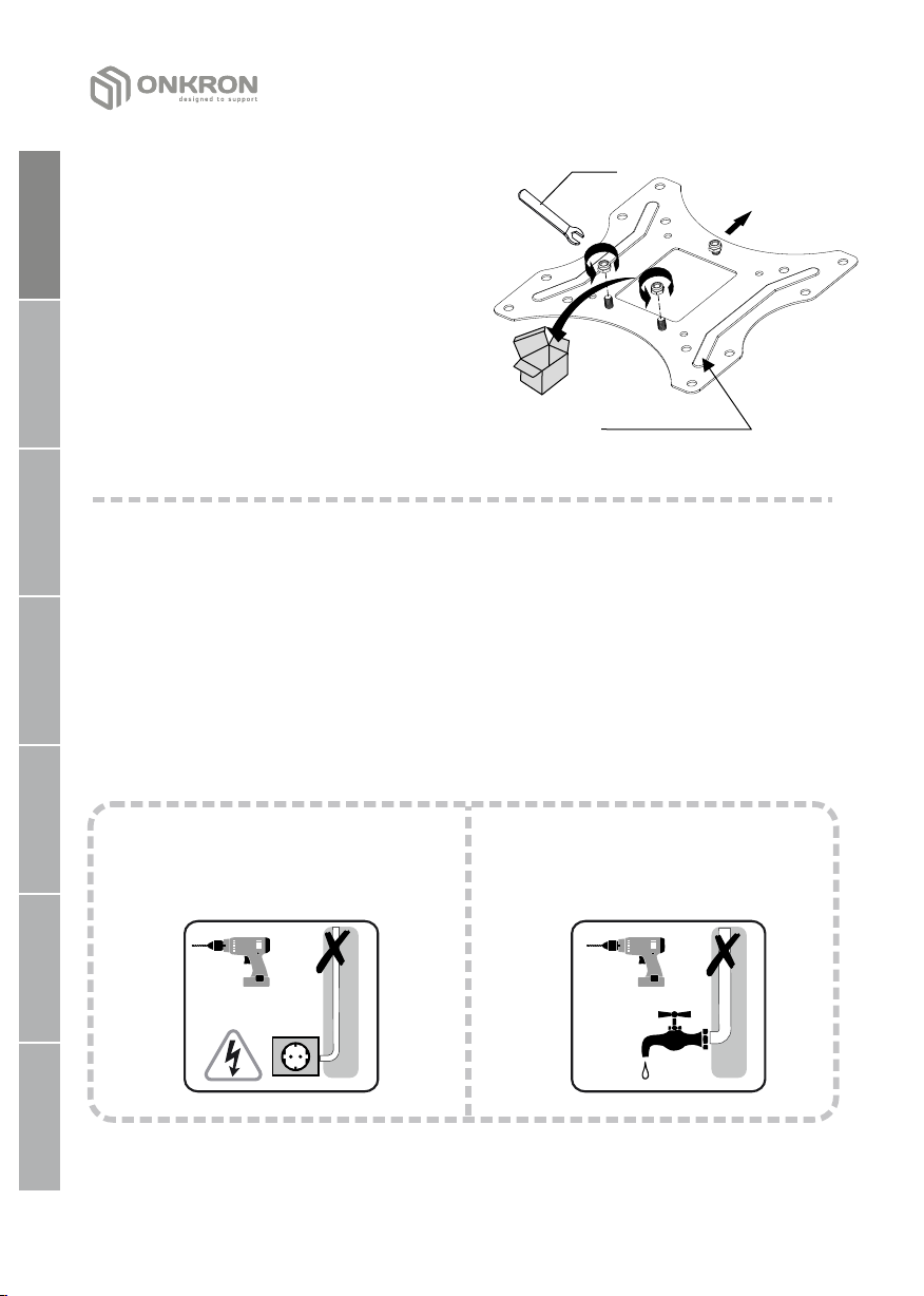
CAUTION
Using the product with devices that exceed allowed weight limit, improper assembly
and installation, including overtightening mounting screws, may lead to failure of your
devices and the product itself, and also cause personal injuries.
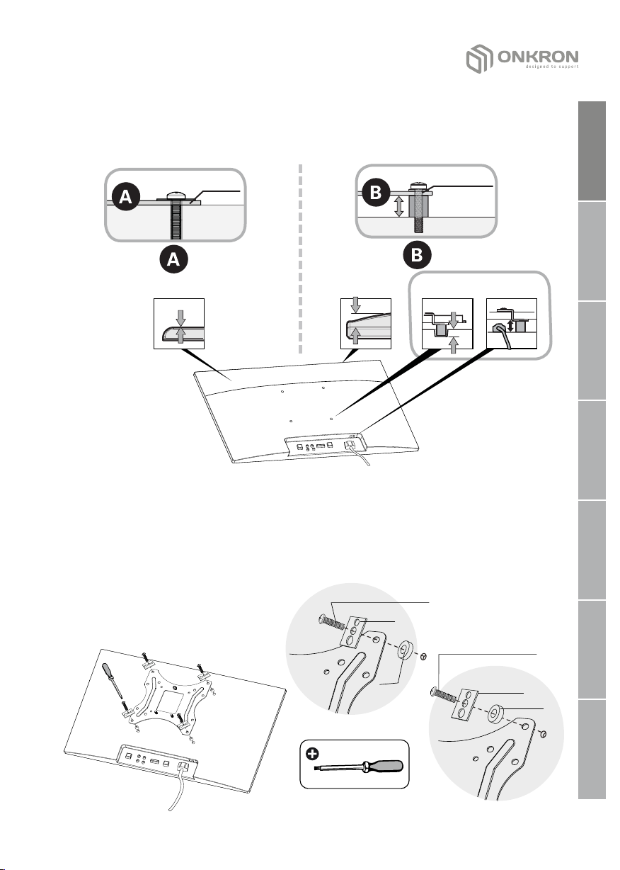
•Рroduct must be assembled as specified in the following assembly instructions.
Improper installation may result in damage or serious personal injuries.
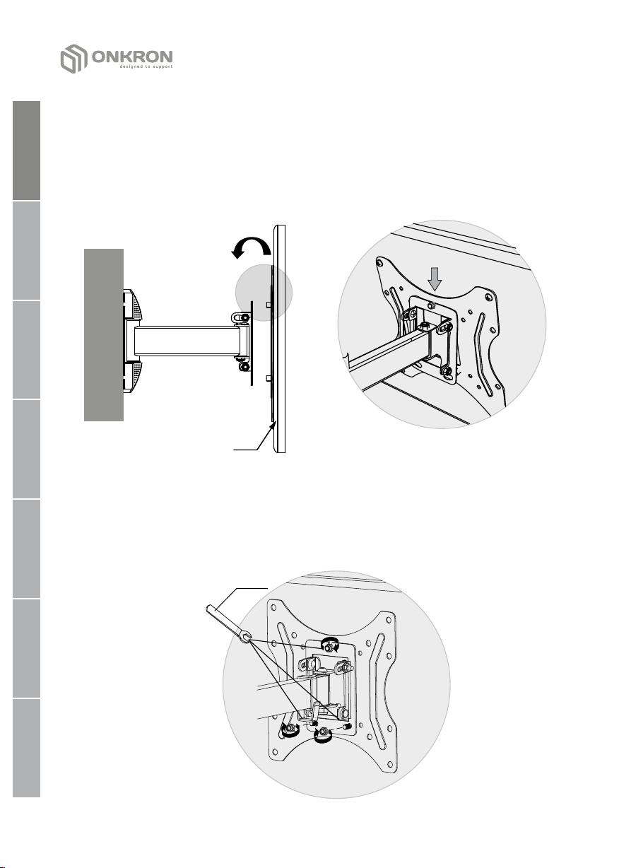
• Safety gear and proper tools must be used. This product should be installed only
by professionals.
• Make sure that working surface will safely support combined weight of the
equipment and all attached hardware and components.
• Use mounting screws provided in the kit and DO NOT OVERTIGHTEN any screws
during assembly of the product.
• This product contains small items that may cause choking if swallowed. Keep
these items away from children.
• Using the product improperly could lead to product failure and personal injuries.
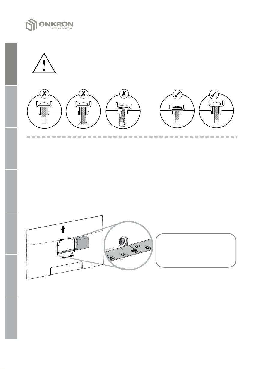
• Before mounting a screen make sure it meets all requirements of the product.
Pay attention to VESA patterns, supported screen weight and diagonal.
• Mounting an unsupported screen could lead to product failure and personal
injuries.
IMPORTANT
Make sure you have received all parts according to the component checklist BEFORE
the installation. If any parts are missing or faulty, contact your local distributor for a
replacement.
WARRANTY
Not under mandatory certification. Unlimited lifespan. 5 YEARS WARRANTY.
MAINTENANCE
Check your product is safe to use at regular intervals (at least every three month).