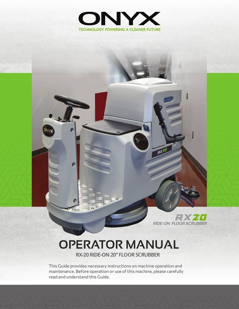
Onyx X Series User manual

OPERATOR MANUAL
This Guide provides necessary instructions on machine operation and
maintenance. Before operation or use of this machine, please carefully
read and understand this Guide.
ONYX X-SERIES PROPANE FLOOR MACHINES
X-SERIES PROPANE
FLOOR MACHINES

Website: https://www.onyxsolutions.store/
No further notice will be given for possible change of specication and parts.
Machine Information:
Please ll in when installing for future reference.
Model number: _____________________________________________________________________
Machine serial number: ____________________________________________________________
Sales representative: _______________________________________________________________
PO number: _________________________________________________________________________
Date PO placed: _____________________________________________________________________
Installation Date: ____________________________________________________________________
12605 Commerce Station Drive • Suite 700
Huntersville, NC 28078
704.827.9368
TABLE OF CONTENTS
Parts Ordering
Warranty Claims
Technical Support
Protect the Environment
Safety Precautions
Safety Information
Description of Safety Symbols
General Operation Safety
Components and Controls
Operation
Preperation
Starting the Engine
Stopping the Engine
Handle Adjustment
Wheel Position Adjustment
Maintenance
Battery Maintenance
Dust Collection Maintenance
How to Change Pad
Storage
Troubleshooting
Propane Safety
Propane Supplimental Operator Manual
About Propane
Filling Propane Cylinders
What You Need to Know
Standards of Use
Troubleshooting Guide
Emission Control System
Emission Control Warranty Statement
4
4
4
4
5
5
6
7
8
8-9
10
10-11
12
12-13
14
14-15
16
16
16
17
17
18
19
20
21
21
21
22-24
25
26-27
28
29
30
31
32-34
35
36-37
Troubleshooting
Carbon Monoxide (CO) Safety
Potential Eects of Carbon Monoxide Exposure
Industry Guidelines for Acceptable Carbon
Monoxide Exposure
Measuring Carbon Monoxide Exposure
Understanding Factors that Determine Carbon
Monoxide Levels
Methods to Reduce Carbon Monoxide Exposure
Air Exchange and CO Diusion
Type of Work Considerations
Examples of CO Management is Spaces
Notes
38-40
41
42
42-43
43
44
44-46
46-47
47
47-48
48-50
51

4 5
PARTS ORDERING
When ordering the replacement parts, please refer to the ONYX website at www.onyxsolutions.com. Use
of the published Illustrated Parts Lists (IPL’s) to identify the correct part number required is required to
support accuracy of parts ordering.
Machine IPL’s can be found at the top of the SHOP page of the ONYX website. Before matching parts
or accessories, please rstly determine your machine model and serial number. You can order parts and
accessories from any authorized service center or dealer by telephone at 704-827-9368, or email us at
sales@onyxsolutions.com.
WARRANTY CLAIMS
ONYX Warranty Statement (policy) and Warranty Claim form can be found on the SUPPORT page of the
ONYX website, https://www.onyxsolutions.store/support.
TECHNICAL SUPPORT
Technical support is available by submitting a HELP TICKET on the CONTACT US page of the ONYX website,
https://onyxsolutions.odoo.com/contact.
PROTECT THE ENVIRONMENT
Please abandon the old machine components such as packaging material, battery,
etc. and toxic liquid such as anti-freezing agent and oil according to your local regu-
lations on waste disposal and on the premise of maintaining environmental safety.
Please ensure to carry out the recycling well.
12605 Commerce Station Dr • Suite 700
Huntersville, NC 28078
704.827.9368
SAFETY PRECAUTIONS
WARNING: Failure to read the Operator Manual prior to operating or attempting any
service or maintenance procedure to your machine could result in death or injury to you
or others, or damage to the machine or to other property. You must have training in the
operation of this machine before using it. If you or your operator/operators cannot read
English, have this manual explained fully before attempting to operate this machine.
WARNING: It is the owner/operator’s responsibility to ensure that the air-exchange
system installed in any location where a propane oor care machine is being operated is
of sucient capacity and quality to support the use of such a machine. OSHA and other
County, State, or Federal Agencies publish guidelines on this subject that are usually most
readily found in the possession of the respective owners and/or parent companies of any
location or chain of locations. Failure on the part of the owner/operator to ensure that a
propane oor care machine can be operated safely in a given location may lead to injury,
sickness or even loss of life.
WARNING: This product contains one or more chemicals known to the State of California
to cause cancer and birth defects or other reproductive harm. Wash hands after handling.
SAFETY INFORMATION
The following terms and symbols are used to identify statements of potential hazards which aect safety
of yourself and others. Read and observe all safety statements found on this Operator Manual and on
your engine.
DANGER:
The signal word DANGER indicates a hazardous situation which, if not avoided according
to the instruction found in this Operator Manual or on your machine, will result in death or
serious bodily injury.
WARNING:
The signal word WARNING indicates a hazardous situation which, if not avoided according
to the instruction found in this Operator Manual or on your machine, could result in death
or serious bodily injury.
CAUTION:
The signal word CAUTION indicates a hazardous situation which, if not avoided according
to the instruction found in this Operator Manual or on your machine, could result in minor
or moderate injury or damage to your engine or property.

6 7
DESCRIPTION OF SAFETY SYMBOLS
The following safety symbols are used on the product and in this manual to alert the operator of
potential safety hazards. Read them carefully, and understand their meaning.
Indicates DANGER, WARNING, or CAUTION
Read Operator Manual before operating his machine. Failure to follow directions could
result in death or serious injury.
Engine exhaust contains carbon monoxide, an odorless and deadly gas. Follow all Carbon
Monoxide Safety instructions in this Operator Manual, Propane Engine Supplemental
Operator Manual, and on machine. Failure to follow directions could result in death or
serious injury.
Do NOT touch hot muer, exhaust pipe, or cylinder. These parts are extremely hot
from operation and may remain hot after operation. Severe burn or injury could
occur if you touch these parts.
Propane is highly ammable. Follow all Propane Safety instructions in this Operator
Manual, Propane Engine Supplemental Operator Manual, and on machine. Failure to
follow directions could result in death or serious injury.
Wear eye and hearing protection when operating this machine.
There are rotating pads and parts under machine frame, which can cause serious
injury. Keep hands and feet away.
GENERAL OPERATION SAFETY
DANGER: Severe burn or injury could occur if you touch the hot muer, exhaust pipe, or
cylinder. Do NOT Touch these hot parts.
WARNING: Any alterations or modications of this engine could result in damage to
the engine or injury to the operator or other bystanders. Alterations or modications
not authorized by the manufacturer voids any and all warranties and liabilities.
WARNING: To avoid injury or property damage, DO NOT leave the machine where it can be
tampered with or started by persons untrained in its operation.
WARNING: Moving parts of this machine can cause serious injury and/or damage. Do not
allow contact of clothing, hair, hands, feet, or other body parts with the rotating pad. Keep
other people away from the machine while it’s in operation. DO NOT leave the machine or
engine running unattended.
WARNING: Operate the machine at a slow or moderate pace. DO NOT run when operating
the machine.
WARNING: Injury to the eyes and/or body can occur if protective clothing and/or equipment
is not worn while using this engine. Always wear safety goggles and safety clothing while using
this machine.
WARNING: Long or continuous exposure to high noise levels may cause permanent hearing
loss. Always wear hearing protection while using this machine.
WARNING: Injury to the operator or bystanders could occur if the machine’s power is on while
changing the bung pad or making machine adjustments. Never try to change the bung pad
or attempt to make machine adjustments while the engine is running.
WARNING: Keep bystanders away from the engine while it is in operation.
WARNING: Substantial damage to the oor, the machine, or personnel may result if the
machine is operated with the pad o center, damaged or missing. Do not operate the
machine if the pad is o center, damaged or missing.
WARNING: Operating an engine that has loose parts could result in injury or property
damage. DO NOT operate this engine if there are loose parts. Inspect the engine for loose
parts frequently. This will promote safe operation and a long engine life.
WARNING: Vibration from machinery may cause numbness or tingling of the ngers in
certain people. Smoking, dampness, diet, and heredity may contribute to the symptoms.
Wearing warm clothing, gloves, exercising and refraining from smoking can reduce the
eects of vibration. If the symptoms still persist, discontinue operation of the machine.
8 9
MACHINE SPECIFICATIONS - JX
Engine Size
Pad Diameter
Net Weight
Gross Weight
Packaged Dimension
Front Wheels
Pulley Ratio
Belt
Engine Idle RPM
Engine MAX RPM
PAD RPM
Propane Cylinder *Varies by model.
603 CC
21 in. / 24 in. / 27 in. *
272 lb
330 lb
52 in. (L) x 30 in. (W) x 44 in. (H)
6 x 1.5 in. (x2)
4:8
BX51
2000
2900 to 3500*
1000 to 1800
20 LB Vertical Vapor
1. Engine
2. Catalytic Muer
3. Machine Deck
4. Shroud
5. Shroud Seal
6. Front Bearing Housing
7. Belt Tensioner
8. Battery
9. Electronic Box & Cover
10. Propane Tank
11. Tank Strap
12. Propane Hose w/ REGO Valve
13. Handle
14. Grips
15. Bonnet Filter
COMPONENTS & CONTROLS - JX
16. Engine Throttle Control
17. Clutch Handles*
18. Handle Adjustment Knob
19. Hour Meter / Tachometer
20. Headlight Switch*
21. Water Switch*
22. Ignition Switch & Key
23. Pad
24. Pad Holder
25. Front Wheels
26. Rear Casters
27. Dust Bag*
28. Dust Chute*
* Not included on all models

10 11
MACHINE SPECIFICATIONS - SX COMPONENTS & CONTROLS - SX

12 13
MACHINE SPECIFICATIONS - TX COMPONENTS & CONTROLS - TX

14 15
MACHINE SPECIFICATIONS - ZX COMPONENTS & CONTROLS - ZX

16 17
OPERATION
CAUTION: OVERHEATING is a major cause of engine failure. Keep the engine clean and free
of debris build up.
CAUTION: Low oil levels and dirty oil account for most of the other failures. Follow the
engine manual’s recommended oil change schedule.
PREPARATION
1. Check engine oil level according to Engine Operator Manual
2. Ensure propane cylinder has been properly lled according to section “Filling Propane Cylinders”
3. Check for any sign of wear or damage such as cracks, corrosion, punctures, etc. to the fuel system includ-
ing propane cylinder, fuel hoses, ttings, regulator, carburetor, and electrical components.
4. Ensure main service valve on propane cylinder is closed (turned clockwise).
5. Screw the REGO tting of the high-pressure propane hose onto the cylinder service valve and hand
tighten. This connection MUST be tight and secure and fully seated to function.
6. Ensure propane tank is secured with clamping strap
7. Ensure handle is secure and at a comfortable position
8. Ensure all machine parts (belt, pad, handle, wheels, etc.) are in place and secure.
9. Ensure the pad is at least 1/3 inch thick, and that the pad holder is tight.
10. Ensure the pad driver is secure to the drive shaft.
11. Ensure the battery cable is connected.
STARTING THE ENGINE
1. Slowly open the main service valve on propane cylinder to the fully open position.
2. Set throttle to Idle position.
3. Ensure machine is rocked back on its rear casters, so the pad is not in contact with the oor.
4. Turn Ignition Switch to “Start”, which will engage starter. Allow cranking for a maximum of 6 seconds or
until the engine res.
If engine fails to re on the rst attempt, repeat this step. It will likely re on the second attempt due to
internal fuel priming.
• 5. Once engine has started, slowly increase throttle. Allow for a warm-up period for 30 Seconds before
applying full load to the engine.
Note: If the engine fails to start, see the Troubleshooting Guide.
WARNING: Before attempting to start engine, become familiar with all controls of the machine.
CAUTION: Serious starter damage will result if starter is engaged for more than 6 seconds, and
will void warranty.
1. Set throttle to Idle position.
2. Close the service valve on propane cylinder (turn clockwise fully).
3. Allow the remaining propane in the regulator and fuel hose to be consumed by engine, until engine stops.
4. Turn engine key switch to o.
5. Disconnect fuel line from propane cylinder.
6. If storing or transporting the machine, follow instructions in section “STORING & TRANSPORTING
PROPANE CYLINDERS”
1. Turn engine key switch to o.
2. Close the service valve on propane cylinder (turn clockwise fully).
3. Disconnect fuel line from propane cylinder.
1. Stop the engine.
2. Loosen the Handle Adjustment Knob, until the Handle is allowed to pivot freely. Note: Do not fully re-
move this knob.
3. Adjust the Handle to desired position.
4. Tighten the Handle Adjustment Knob.
STOPPING ENGINE
Normal Stop
Follow these stopping procedures under normal use, including when the engine will be stored or transported:
Immediate Stop
Follow these stopping procedures only when an immediate stop is required:
The handle on this machine can be adjusted to several heights, to accommodate dierent sized operators
and dierent operator preferences. To adjust the handle:
HANDLE ADJUSTMENT

18 19
The position of the two front wheels has signicant aect on the performance and handling of the
machine, including:
Pad pressure = The amount of force the pad has against the oor
Forward propulsion = The feeling of forward pull or drive caused by pad friction
Machine torque = The feeling that the machine wants to constantly turn, usually toward the left
When your machine was assembled, the wheels were installed in positions determined to allow for best
performance under most conditions. However, depending on oor type, oor nish type, pad type, and
operator preference, these wheel positions can be changed to aect machine performance.
For the purpose of clarity, the following terms will be used in this section:
Forward = closer to the front of the machine
Rearward = closer to the rear of the machine
Up = closer to the sky
Down = closer to the ground
Left = the left side when viewed from the Operator’s position
Right = the right side when viewed from the Operator’s position
Through wheel adjustment, the following changes can be made to the machine performance:
WHEEL POSITION ADJUSTMENT
Desired Change
Increase pad pressure
Decrease pad pressure
Increase forward propulsion
Decrease forward propulsion
Increase machine torque
Decrease machine torque
To change the wheel position:
1. Stop the engine.
2. Adjust handle position to highest position and rock machine back, until handle grips are resting on
ground.
3. Remove the small cotter pin / hair pin from the wheel axle.
4. Remove the wheel axle.
5. Remove the wheel and any spacer.
6. Reposition the wheel and spacer in desired hole.
7. Insert the wheel axle.
8. Insert the cotter pin / hair pin.
CAUTION: Whenever working on a machine in the rocked back position, ask an assistant to
hold the handle and prevent the machine from falling forward.
Adjustment to Make
Move both wheels (left and right) Rearward
Move both wheels (left and right) Forward
Oset the two wheels, so the right wheel is Higher (more “up”) than left
Align the two wheels, so the left and right wheel are the same height
Move both wheels (left and right) Down
Move both wheels (left and right) Up
MAINTENANCE SCHEDULE
Daily 25hr 200hr
Check Engine Oil Level X
Check for Loose Hardware X
Check for Fuel or Oil Leakage X
Check/Clean Intake Air Filter X
Check/Clean Bonnet Filter X
Check, Clean, and/or Replace Dust Bag X
Check Pad X
Check Shroud & Shroud Seal X
Check Engine Mounts X
Check Belt for Wear or Slippage X
Check Pulleys, Drive Shaft, and Bearings X
Check Wheels & Bearings X
Overall Checkup at Authorized Service Center X
WARNING: To ensure personal safety, adjustments should ONLY be made by a qualied
technician or an authorized service enter.
WARNING: Prior to any maintenance, ensure engine is turned o and disconnect spark plug
wire from spark plug. Never attempt service or maintenance on a running engine.
MAINTENANCE

20 21
The equipment uses an onboard charging system integrated within the wiring harness which charges bat-
tery during normal use.
The battery can be recharged oine with any o-the-shelf battery charger with the following specs:
Voltage = 12 volts
Charging Amperage = 0.5 to 15 Amps
Battery Specs:
Model
Volltage (V)
Capacity (Ah)
Weight
Charging Current
Charging Voltage
Cold Cranking Amps
Cycle Life
HJTZ5S-30-GFP
12.8
3
0.7 kg / 1.5 lb
0.5A to 15A
14.4 0.5 V
180
≥1000
BATTERY MAINTENANCE
Battery Charging Procedures:
1. Disconnect the plastic battery cable terminal on equipment, and remove battery from equipment.
2. Connect the charger clamps to the battery posts:
• Red clamp on the positive “+” post
• Black clamp on the negative “-” (ground) post
3. If the charger has settings, set the output voltage and amperage within the ranges noted above.
4. Plug in the battery charger to standard wall outlet in a well ventilated area.
5. For best results, leave the charger connected for minimum of 8 hours.
6. Disconnect battery from charger by reversing steps 5-2
7. Reinstall battery on equipment, and connect the plastic battery cable terminal.
Take the following steps when storing the machine:
1. Ensure the ignition switch is turned to “o”.
2. Remove the propane tank, and store in an approved outside location.
3. Disconnect battery cable connectors, to prevent battery drain. When disconnected, the battery will keep
its charge in storage
for approximately 12 months.
4. Store machine in an indoor, climate controlled location with low humidity.
If equipped with a dust collection system, the dust bag should be serviced frequently as follows:
Note: The bag will remain functional for approximately 20-30 cycles, after which the bag should be replaced.
1. Stop engine.
2. Remove the bag from the dust chute, but pulling the elbow out of the dust chute.
3. Unzip the back of the bag.
4. Empty the contents of the bag into a garbage receptacle and shake out any debris. This is best done out-
side.
5. Reinstall the bag onto the dust chute, and secure the bag to machine via the rope loop and velcro on bag.
1. Stop the engine.
2. Adjust handle position to highest position and rock machine back, until handle grips are resting on
ground.
3. Remove the Pad Holder by turning it counterclockwise.
4. Remove the Pad, by pealing it o of the gripper surface
5. Install a new Pad onto the gripper surface, paying attention to keep it centered and aligned with the grip-
per surface.
6. Reinstall the Pad Holder, and tighten it by turning it clockwise.
DUST COLLECTION MAINTENANCE
HOW TO CHANGE PAD
WARNING: Whenever working on a machine in the rocked back position, ask an assistant to
hold the handle and prevent the machine from falling forward.
STORAGE

22 23
Note: When troubleshooting, always rst check for simple causes which may at rst seem too obvious.
For example, an engine unable to start may be caused by an empty propane cylinder or an unopened
service valve.
Engine does not turn
over.
Weak or dead battery.
Battery cable is disconnected.
Igntion switch faulty.
Faulty Starter.
Damaged or disconnected wire in
wiring harness.
Numerous other causes.
Recharge or replace battery.
Connect battery cable at connector.
Check switch, replace if necessary.
Check starter, replace if necessary.
Check wiring harness to identify faulty connection,
replace or reconnect as required.
See engine manual or dealer.
SYMPTOM POSSBLE CAUSE CORRECTIVE ACTION
TROUBLESHOOTING
Engine turns over, but
does not start or run.
Propane cylinder is empty.
Main fuel service valve on propane
cylinder is closed.
REGO tting (fuel hose to cylinder
connector) is not fully seated.
Propane cylinder OPD (overow pro-
tection device) has been triggered.
Propane regulator out of
adjustment or faulty.
Poor quality propane causes deposits
of particles in regulator or valves.
Spark plug not ring.
Faulty oil pressure switch.
Numerous other causes.
Rell cylinder or replace with full cylinder.
Manually open main fuel service valve on propane
cylinder.
Manually close main fuel service valve. Disconnect
REGO tting. Reconnect and hand tighten to ensure
secure connector is fully seated. Slowly open main fuel
service valve.
Manually close main fuel service valve. Disconnect
REGO tting. Wait 5 seconds. Reconnect and hand
tighten to ensure secure connector is fully seated.
Slowly open main fuel service valve.
Have certied dealer inspect regulator and adjust or
replace.
Have certied dealer inspect regulator and clean or
replace. Service engine valves according to engine
manual instructions. Contact propane supplier to pro-
vide clean HD5 propane.
Replace spark plug.
Check or replace oil pressure switch.
See engine manual or dealer.
Propane regulator
freezes and prevents
ow of propane.
Liquid propane is entering
regulator.
Low ambient temperature.
• Ensure cylinder is designed for VAPOR withdrawal.
• Ensure cylinder is designed for the correct orientation
(horizontal or vertical).
• Ensure cylinder is installed in correct orientation.
Make sure locator pin is inserted into positioning slot
on cylinder collar, and follow orientation arrow indica-
tions/labels on cylinder.
• Ensure propane cylinder is not overlled.
• Ensure use of application does not allow operating
angles to exceed equipment OEM instructions.
It is normal condition for propane regulator to operate
at colder temperature than ambient, which may cause
condensation or frost formation depending on ambient
temperature and humidity levels.
Propane cylinder
forms condensation
or ice.
Inconsistent or short
cylinder run time.
Engine backres, dicult
to start, reduced power,
over-heating, or other
poor performance
Propane fuel is leaking.
Propane consumption is abnormally
high.
Low ambent temperature.
Propane cylinders not lled
consistently.
Propane regulator out of
adjustment or faulty.
Dirty air lter.
Excessive engine load.
Excessive engine RPM
Propane regulator out of adjustment
or faulty.
Propane ow restricted.
Dirty air lter.
Dirty propane lter.
Ignition system faulty.
Poor compression.
Engine timing issue.
Cooling Fins Clogged.
Numerous causes.
Close propane main fuel service valve. Check fuel lines,
REGO tting, and regulator for any leaks.
Refer to section “Inconsistent or short cylinder run
time” below.
It is normal condition for propane cylinder to operate
at colder temperature than ambient, which may cause
condensation or ice formation depending on ambient
temperature and humidity levels.
Use cylinders that are properly and consistently lled
to the 80% maximum level.
Have certied dealer inspect regulator and adjust.
Service air lter.
See engine manual or dealer.
Have certied dealer inspect regulator and adjust.
Refer to section “Engine turns over, but does not start
or run”, above.
Service air lter.
Service propane lter.
Check or replace ignition coils.
See engine manual or dealer.
SYMPTOM POSSBLE CAUSE CORRECTIVE ACTION
TROUBLESHOOTING
Excessive machine
vibration.
Clutch failure.
Pad is not centered on pad
driver.
Pad driver is damaged.
Front end bearings are
worn/damaged.
Blown fuse.
Disconnected wire at clutch.
Disconnected wire under
ignition switch.
Remove pad and reinstall, paying attention to center it
on pad driver.
Inspect pad driver and replace if necessary.
Inspect front end bearings and replace if necessary.
Check fuses in Electronic Box and replace if necessary.
Check wires that connect the actual clutch to the
wiring harness. Reconnect if necessary.
Check wires that connect clutch handles to wiring
harness located under the ignition switch. Reconnect if
necessary.

24 25
TROUBLESHOOTING
Battery is not being
charged during machine
running.
Engine monitor shuts
down machine.
Battery does not hold a
charge.
Engine is running rich.
Engine monitor is faulty.
Battery is faulty.
Faulty voltage regulator.
Damaged or disconnected
wire in wiring harness.
Have certied dealer inspect regulator and adjust.
Replace engine monitor.
Replace battery.
Replace voltage regulator.
Check wiring harness to identify faulty connection,
replace or reconnect as required.
SYMPTOM POSSBLE CAUSE CORRECTIVE ACTION
PROPANE SAFETY
This machine is powered by an engine that uses propane fuel. Additional information about propane
basics, propane cylinders, lling propane cylinders, and storing and transporting propane cylinders is
provided in the “Propane” section of this operator manual. The following propane safety instructions
should be fully understood and followed at all times when using this machine or propane cylinders.
Failure to follow directions could result in death or serious injury.
DANGER: Propane is a highly ammable fuel. Cigarette lighters, pilot lights, and any other
sources of ignition can create an explosion when in contact with propane. All sources of
ignition should be extinguished or removed entirely from the work area. DO NOT SMOKE
in the vicinity of a propane powered engine, machine, or propane cylinder.
WARNING: If you smell propane gas, shut o the machine and turn o service valve on
propane cylinder and move machine outside. Determine the source of the leak before using
it again.
DANGER: NEVER release or bleed propane inside any building or other enclosed
space or near an open pit. Check for fuel leaks and damage to the propane cylinder
prior to operating machine and storage. Turn o service valve on propane cylinder
when machine is not in use. Always store propane cylinder in an approved outside
location. It is UNLAWFUL to store a propane cylinder inside a building.
WARNING: Escaping propane can freeze skin and cause frostbite and damage eyesight.
Always wear safety gloves and safety glasses when lling propane cylinders.

26 27
PROPANE SUPPLEMENTAL OPERATOR MANUAL
INTRODUCTION:
This Operator’s Manual provides important information about safety, operation, transportation, storage
maintenance, and warranty of your propane engine and propane cylinders.
The following terms and symbols are used to identify statements of potential hazards which aect safety
of yourself and others. Read and observe all safety statements found on this Operator Manual and on your
engine.
DANGER: The signal word DANGER indicates a hazardous situation which, if not avoided
according to the instruction found in this Operator Manual or on your engine, will result in
death or serious bodily injury.
WARNING: The signal word WARNING indicates a hazardous situation which, if not avoid
ed according to the instruction found in this Operator Manual or on your engine, could
result in death or serious bodily injury.
CAUTION: The signal word CAUTION indicates a hazardous situation which, if not avoided
according to the instruction found in this Operator Manual or on your engine, could result in
minor or moderate injury or damage to your engine or property.
IMPORTANT SAFETY INSTRUCTIONS:
DANGER:
• Propane is a highly ammable fuel. Cigarette lighters, pilot lights, and any other sources of ignition can
create an explosion when in contact with propane. All sources of ignition should be extinguished or re-
moved entirely from the work area. DO NOT SMOKE in the vicinity of a propane powered engine or pro-
pane cylinder. If you smell propane gas, shut o the engine. Determine the source of the leak before using
it again. NEVER vent propane gas inside a building. It is UNLAWFUL to store a propane cylinder inside a
building.
• Severe burn or injury could occur if you touch the hot muer or exhaust pipe. DO NOT TOUCH THE
HOT MUFFLER OR EXHAUST PIPE.
• The combustion of propane by this engine produces carbon monoxide, a deadly, colorless, odorless,
poisonous gas. This engine is specically calibrated to operate at a very “lean” air/fuel ratio which minimiz-
es the production of carbon monoxide. Additionally, a catalyst muer is provided with this engine which
specically targets and eliminates any remaining carbon monoxide, making it safe to operate indoors.
• DO NOT OPERATE THIS ENGINE WITHOUT THE CATALYST MUFFLER.
• DO NOT TAMPER WITH REGULATOR OR OTHER SETTINGS WHICH WOULD ALTER AIR/FUEL RATIO.
• INSURE ANY INDOOR SITE OF USE HAS ADEQUATE VENTILATION WHICH MEETS INDUSTRY STANDARDS
WARNING:
• Propane is a highly ammable fuel. Cigarette lighters, pilot lights, and any other sources of ignition can •
Failure to read the Operator Manual prior to operating or attempting any service or maintenance proce-
dure to your engine could result in injury to you or others, or damage to the engine or to other property.
PROPANE SUPPLEMENTAL OPERATOR MANUAL
You must have training in the operation of this engine before using it. If you or your operator/operators
cannot read English, have this manual explained fully before attempting to operate this engine.
• Any alterations or modications of this engine could result in damage to the engine or injury to the
operator or other bystanders. Alterations or modications not authorized by the manufacturer voids
any and all warranties and liabilities.
• To avoid injury or property damage, DO NOT leave the engine where it can be tampered with or start-
ed by persons untrained in its operation.
• DO NOT leave the engine running unattended.
• Operating an engine that has loose parts could result in injury or property damage. DO NOT operate
this engine if there are loose parts. Inspect the engine for loose parts frequently. This will promote safe
operation and a long engine life.
• Keep bystanders away from the engine while it is in operation.
• Injury to the eyes and/or body can occur if protective clothing and/or equipment is not worn while
using this engine. Always wear safety goggles and safety clothing while using this engine.
• Long or continuous exposure to high noise levels may cause permanent hearing loss. Always wear
hearing protection while using this engine.
• Injury to the operator or bystanders could occur if the engine is running. Never attempt to make en-
gine adjustments while the engine is running.
• Dangerous carbon monoxide emissions from this engine will increase greatly due to a dirty air cleaner.
Follow the engine manufacturer’s air cleaner service instructions.
CAUTION:
• Overlling propane cylinders is the number one cause of damage to the propane fuel system. This fuel
system is designed to run o vapor propane, not liquid propane. When the cylinder is overlled, liquid
propane will enter the fuel system and can damage lock-o and regulator, in addition to causing the engine
to run poorly or not at all. This voids the warranty on aected parts of the engine. To avoid problems, read
and understand fully, the section “FILLING PROPANE CYLINDERS”.
• OVERHEATING is a major cause of engine failure. Keep the engine clean and free of debris build up.
• Low oil levels and dirty oil account for most of the other failures. Follow the engine manual’s recom-
mended oil change schedule.

28 29
ABOUT PROPANE
• Propane is ammable and commonly used as a fuel.
• The molecular formula of propane is C3H8, and it is in the family of liqueed petroleum gases (LP gases).
The other LP gases include butane, propylene, butadiene, butylene, isobutylene and mixtures thereof.
• Propane is commonly available and has proven to be a dependable, safe, economical, and clean burning fuel.
It can be used as a household fuel, industrial fuel, and fuel for internal combustion engines. Propane has been
used as a fuel since 1910.
• At atmospheric pressure, propane boils at -44 degrees Fahrenheit, meaning it typically exists as a vapor.
However, when contained under pressure, such as in a propane cylinder, it can exist as a liquid.
• Propane is naturally odorless, but includes an additive odorant, usually mercaptan, which gives it a distinct
odor similar to rotten eggs or skunk.
• Vapor propane is heavier than air, meaning it will settle in low areas such as along the ground or in drains.
PROPANE CYLINDERS (TANKS):
Propane cylinders are constructed according to ASME and Federal DOT #4ET20 pressure safety codes. All
valves and ttings are UL Listed. Propane gas is noncorrosive and will not rust the inside of a cylinder. It
is recommended to have propane cylinders inspected regularly during re-ll by an authorized National LP
Gas Association propane dealer. The fuel cylinder is supplied directly from the manufacturer and is void of
propane.
PROPANE CYLINDER CONFIGURATIONS:
Propane cylinders are constructed to function in specic congurations. The primary conguration options
are:
• Propane Withdrawal: Vapor or Liquid
• Cylinder Orientation: Horizontal or Vertical
IMPORTANT: Dierent cylinder congurations are not interchangeable.
All ONYX engines use Vapor cylinders, and the orientation can be either Horizontal or Vertical.
WARNING: NEVER use a cylinder not intended engine fuel applications. DO NOT substitute
cylinders that are used with a barbecue grill, etc.
CAUTION: Do not use propane cylinders that are liquid withdrawal cylinders, such as cylinders
for fork lift trucks or other liquid withdrawal applications.
label that say “THIS SIDE UP” or equivalent.
CAUTION: Failure to use a proper cylinder or failure to install cylinder in proper orientation will
result in liquid propane withdrawal and cause damage the regulator.
FILLING PROPANE CYLINDERS
WARNING:
• Propane cylinders should only be lled by your propane provider or by individuals who have been proper-
ly trained and certied.
• Escaping propane can freeze skin and cause frostbite and damage eyesight. Always wear safety gloves
and safety glasses when lling propane cylinders.
• DO NOT overll cylinders.
• DO NOT tamper with cylinder gauges or safety relief valves.
• At time of ll, ensure tank is in operable condition and meets all certication requirements. Discontinue
use of any cylinder that is damaged or rusted or does not comply with certication requirements. Your
propane service company will assist with compliance.
STORING & TRANSPORTING PROPANE CYLINDERS:
The NFPA Technical Committee prohibits the storage of propane cylinders in buildings. Propane cylinders
should NOT be stored in buildings used by the public or frequented by anyone passing through or who is
working in the building. Full or empty, never leave cylinders in small enclosed areas. Cylinders must be
stored in a secure, tamper-proof storage enclosure that provides safety from accident or vandalism.
Propane cylinders should always be transported either secured to the machine using cylinder straps, or
secured in an upright position during transportation.
• Relief valve opens due to over pressurized cylinder creating hazardous situation.
• Moisture in the cylinder.
• Powered engine operates initially but shuts down when propane mixture becomes too lean.
The maximum ll volume of a propane cylinder is ALWAYS considered 80% of the total cylinder volume to
allow for expansion and to ensure proper vapor withdrawal from the cylinder.
For example, if your propane cylinder is referred to as a “20 lb cylinder”, this means that when the propane
cylinder is 80% full, the weight of the propane is 20 lb.
Cylinders should be lled in the vertical position.
When lling a propane cylinder, the xed liquid level gauge should be opened (unscrewed counterclock-
wise) so it can be used to determine when propane has reached 80% full. As propane is added during lling,
vapor will escape the small hole in this gauge. When the cylinder reaches 80% full, the escaping propane
will turn to liquid propane. When this happens, the lling should be immediately stopped and the gauge
should be closed (turned clockwise).
should be familiar with this operation and will provide this service.

30 31
WHAT YOU NEED TO KNOW
The engine performance, reliability and life are inuenced by many factors, some external and some
strictly associated with the quality of the products used and with the scheduled maintenance.
The following information allow a better understanding and use of your engine.
ENVIRONMENTAL CONDITIONS:
The operation of a four-stroke endothermic engine is aected by:
a) Temperature:
– Working in low temperatures could lead to a dicult cold starting.
– Working in very high temperatures could lead to a dicult hot starting due to the evaporation
of the fuel either in the carburetor oat chamber or in the pump.
– In any case, the right kind of oil must be used, according to the operating temperatures.
b) Altitude:
– The higher the altitude (above sea level), the lower the max power developed by an endothermic
engine.
– When there is a considerable increase in altitude, the load on the machine should be reduced and
particularly heavy work avoided.
OIL:
Use always high quality oils, choosing their viscosity grade according to the operating temperature.
a) Use only detergent oil classied SJ,SL or higher are acceptable.
b) Choose the SAE viscosity grade of oil from this chart:
– from 5 to 35 °C = SAE 30
– from -25 to + 5 °C = 5W-20 or 5W-30 (Multi-viscosity)
– from -7 to + 35 °C = Synthetic oils 10W-30 or 15W-40 (Multi-viscosity)
c) The use of multi-viscosity oils in hot temperatures will result in higher than normal oil consumption;
therefore, check oil level more frequently.
d) Do not mix oils of dierent brands and features.
e) SAE 30 oil, if used below 5°C, could result in possible engine damage due to inadequate lubrication.
f) Oil should be at “MAX” mark do not overll. Overlling with oil may cause:
– Smoking;
– Spark plug or air lter fouling, which will cause hard starting.
AIR FILTER:
A good quality fuel is the major issue for the engine reliability of operation. The air lter must always
be in perfect working order, to prevent debris and dust from getting sucked into the engine, reducing
the eciency and life of the machine.
a) Always keep the ltering element free of debris and in perfect working order.
b) If necessary, replace the ltering element with an original spare part. Incompatible ltering ele-
ments can impair the eciency and life of the engine.
c) Never start the engine without mounting the ltering element properly.
WHAT YOU NEED TO KNOW
SPARK PLUG:
Not all the spark plugs for endothermic engines are the same!
a) Use only spark plugs of the recommended type, with the right heat range.
b) Check the length of the thread, because – if too long – it will damage the engine beyond repair.
c) Make sure that the electrodes are clean and their gap is correct.
STANDARDS OF USE
BEFORE EVERY USE:
Before every use, perform the following checking procedures in order to assurea regular operation.
CHECK THE OIL LEVEL:
See the specic chapter for the oil to be used.
a) Place the engine level.
b) Clean around oil ll.
c) Unscrew the cap, clean the end of the dipstick and insert it, as illustrated, without screwing it down.
d) Remove the cap with the dipstick and check the oil level that must be between “MIN” and “MAX”
marks.
e) If oil is required, add oil of the same kind up to the “MAX” mark, being careful not to spill any outside
the oil ll.
f) Fully tighten the llercap and wipe o any spilled oil.
CHECK THE AIR CLEANER:
The eciency of the air lter is fundamental for the engine to work properly. Do not start the engine if
the ltering element is missing or broken.
a) Clean around the lter cover.
b) Open the clips of the two sides of the air lter cover.
c) Check the condition of the ltering element. It must be intact, clean and in pefect working order; if
not, either carry out maintenance or replace it.
d) Put the cover back.
LONG STORAGE (OVER 30 DAYS):
In case the engine has to be stored for a long time (for example at the end of the season), a few precautions
are needed to help the future start-up.
a) To prevent the formation of deposits inside the tank, empty it of fuel by unscrewing the carburettor
oat chamber plug and collecting all the fuel in a suitable container. At the end of the operation remember
to screw the plug back on and fully tighten it.
b) Remove the spark plug and pour about 3 cl of clean engine oil into the spark plug hole, then, having
blocked the hole with a rag, run the starter motor briey to turn the engine for a few revs and distribute the
oil over the inner surface of the cylinder. Finally replace the spark plug without connecting the cable cap.

32 33
TROUBLESHOOTING GUIDE
Engine does not turn over
Engine turns over, but
does not start or run
Weak or dead battery
Ignition switch faultyNumerous other causes
Recharge or replace battery.
Check or replace switch.
Problem Reason Solution
Safety interlock switch (operator presence control)
not engaged
Check or replace safety interlock switch
(operator presence control).
Faulty safety interlock switch (operator presence
control)
Engage safety interlock switch (operator
presence control) prior to engaging starter.
Numerous other causes See engine manual or dealer.
Propane cylinder is empty Rell cylinder or replace with full cylinder.
Main fuel service valve on propane cylinder is
closed
REGO tting (fuel hose to cylinder connector)
is not fully seated
Manually open main fuel service valve on
propane cylinder.
Have certied dealer inspect regulator and
adjust or replace.
Manually close main fuel service valve. Dis-
connect REGO tting. Reconnect and hand
tighten to ensure secure connector is fully
seated. Slowly open main fuel service valve.
Propane cylinder OPD (overow protection
device) has been triggered.
Poor quality propane causes deposits of
particles in regulator or valves
Propane regulator out of adjustment or faulty
Manually close main fuel service valve.
Disconnect REGO tting. Wait 5 seconds.
Reconnect and hand tighten to ensure
secure connector is fully seated. Slowly
open main fuel service valve.
Have certied dealer inspect regulator
and clean or replace. Service engine valves
according to engine manual instructions.
Contact propane supplier to provide clean
HD5 propane.
Spark plug not ring
Faulty vacuum switch
Faulty oil pressure switch
Numerous other causes
Replace spark plug.
Check or replace vacuum switch.
Check or replace oil pressure switch.
See engine manual or dealer.
These troubleshooting steps are specic for propane fuel system issues. For other engine issues, refer to the
Engine Operator Manual and/or OEM Equipment Manual.
TROUBLESHOOTING GUIDE
Propane regulator freezes
and prevents ow of
propane
Propane cylinder forms
condensation or ice
Inconsistent or short
cylinder run time
Liquid propane is entering regulator
Low ambient temperature
Propane fuel is leaking
Propane consumption is abnormally high
Low ambient temperature
Propane cylinders not lled consistently
Propane regulator out of adjustment or faulty
• Ensure cylinder is designed for VAPOR
withdrawal and the correct orientation
(horizontal or vertical).
• Ensure cylinder is installed in correct ori-
entation. Make sure locator pin is inserted
into positioning slot on cylinder collar, and
follow orientation arrow indications/labels
on cylinder.
• Ensure propane cylinder is not overlled.
• Ensure use of application does not allow
operating angles to exceed equipment OEM
instructions.
It is normal condition for propane regula-
tor to operate at colder temperature than
ambient, which may cause condensation
or frost formation depending on ambient
temperature and humidity levels.
Close propane main fuel service valve.
Check fuel lines, REGO tting, and regulator
for any leaks.
Refer to section “Inconsistent or short cylin-
der run time” below.
Use cylinders that are properly and consis-
tently lled to the 80% maximum level.
Have certied dealer inspect regulator and
adjust.
It is normal condition for propane cylinder
to operate at colder temperature than am-
bient, which may cause condensation or ice
formation depending on ambient tempera-
ture and humidity levels.
Problem Reason Solution
Dirty air lter
Excessive engine load
Excessive engine RPM
Service air lter.
See engine manual or dealer.

34 35
TROUBLESHOOTING GUIDE
Engine backres, dicult
to start, reduced power,
over-heating, or other
poor performance
Problem Reason Solution
Propane regulator out of adjustment or faulty
Propane ow restricted
Have certied dealer inspect regulator and
adjust.
Refer to section “Engine turns over, but does
not start or run”, above.
Dirty air lter
Ignition system faulty
Poor compression
Engine timing issue
Cooling Fins Clogged
Numerous causes
Service air lter.
Check or replace ignition coils.
See engine manual or dealer.
EMISSION CONTROL SYSTEM
To protect the environment the manufacturer has incorporated (1) crankcase emission and (2) exhaust
emission control systems (EM) in compliance with applicable regulations of the United States Environ-
mental Protection Agency and California Air Resources Board.
1. Crankcase Emission Control System. A sealed-type crankcase emission control system is used to elimi-
nate blow-by gases. The blow-by gases are led to the breather chamber through the crankcase where it is
led to the air cleaner. Oil is then separated from the gases while passing through the inside of the breather
chamber from the crankcase, and then returned back to the bottom of crankcase.
2. Exhaust Emission Control System. The exhaust emission control system applied to this engine consists
of a carburetor and an ignition system having optimum ignition timing characteristics. The carburetor has
been calibrated to provide lean air/propane mixture characteristics and optimum propane economy with a
suitable air cleaner and exhaust system.
TAMPERING WITH EMISSION CONTROL SYSTEM PROHIBITED
Federal law and California State law prohibits the following acts or the causing thereof: (1) the removal or
rendering inoperative by any person other than for purposes of maintenance, repair, or replacement, of
any device or element at design incorporated into any new engine for the purpose of emission control prior
to its sale or delivery to the ultimate purchaser or while it is in use, or (2) the use of the engine after such
device or element of design has been removed or rendered inoperative by any person.
Among acts presumed to constitute tampering involve the parts/systems listed below:
• Carburetor and internal parts
• Spark plugs
• Magneto or electronic ignition system
• Propane lter element
• Air cleaner elements
• Crankcase
• Cylinder heads
• Breather chamber and internal parts
• Intake pipe and tube

36 37
EMISSION CONTROL WARRANTY STATEMENT
EPA & CALIFORNIA EMISSION CONTROL WARRANTY STATEMENT
YOUR WARRANTY RIGHTS AND OBLIGATIONS
Federal law and California State law prohibits the following acts or the causing thereof: (1) the removal or
The California Air Resources Board (CARB), the U.S. Environmental Protection Agency (EPA), and LEHR,
LLC (herein “LEHR”) are pleased to explain the emissions control system warranty on your 2015 small
o-road engine (SORE). In California, new SORE must be designed, built and equipped to meet the State’s
stringent anti-smog standards. LEHR must warrant the emission control system on your SORE for the
period of time listed below provided there has been no abuse, neglect or improper maintenance of your
SORE.
Your emission control system may include parts such as the carburetor, fuel-injection system, the ignition
system, catalytic converter, fuel tanks, fuel lines, fuel caps, valves, canisters, lters, vapor hoses, clamps,
connectors, and other associated emission-related components.
Where a warrantable condition exists, LEHR will repair your SORE at no cost to you including diagnosis,
parts and labor.
The emission control system is warranted for 1000 hours (JLHRS.9992EM family) and 500 hours
(JLHRS.6032EM family). If any emission-related part on your equipment is defective, the part will be repaired
or replaced by LEHR.
As the small o-road engine (SORE) owner, you are responsible for the performance of the required mainte-
nance listed in your owner’s manual. LEHR recommends that you retain all receipts covering maintenance of
your SORE engine, but LEHR cannot deny warranty solely for the lack of receipts or for your failure to ensure
the performance of all scheduled maintenance.
As the SORE owner you should however be aware that LEHR may deny your warranty if your SORE or its part
has failed due to abuse, neglect, improper maintenance or unapproved modication.
You are responsible for presenting your utility equipment engine to a LEHR distribution center as soon as the
problem exists. The warranty repairs should be completed within a reasonable amount of time, not to exceed
30 days. If you have any questions regarding your warranty rights and responsibilities, you should contact
LEHR.
LEHR warrants to the ultimate purchaser and each subsequent purchaser that the equipment is:
Designed, built and equipped so as to conform with all applicable regulations; and
Free from defects in materials and workmanship that cause the failure of a warranted part to be identical in all
material respects to that part as described in the application for certication.
The warranty period begins on the date the equipment is delivered to an ultimate purchaser or rst placed
into service. The warranty period is 1000 hours (FNYXS.9992EM family) and 500 hours (FNYXS.6032EM
family).
Subject to certain conditions and exclusions as stated below, the warranty on emission-related parts is as
follows:
MANUFACTURER’S WARRANTY COVERAGE
OWNER’S WARRANTY RESPONSIBILITIES
GENERAL EMISSIONS WARRANTY COVERAGE
(1) Any warranted part that is not scheduled for replacement as required maintenance in the written in-
structions supplied, is warranted for the warranty period stated above. If the part fails during the period of
warranty coverage, the part will be repaired or replaced by LEHR according to subsection (4) below. Any
such part repaired or replaced under warranty will be warranted for the remainder of the period.
(2) Any warranted part that is scheduled only for regular inspection in the written instructions supplied is
warranted for the warranty period stated above. Any such part repaired or replaced under warranty will be
warranted for the remaining warranty period.
(3) Any warranted part that is scheduled for replacement as required maintenance in the written instruc-
tions supplied is warranted for the period of time before the rst scheduled replacement date for that
part. If the part fails before the rst scheduled replacement, the part will be repaired or replaced by LEHR
according to subsection (4) below. Any such part repaired or replaced under warranty will be warranted for
the remainder of the period prior to the rst scheduled replacement point for the part.
(4) Repair or replacement of any warranted part under the warranty provisions herein must be performed
at a warranty station at no charge to the owner.
(5) Notwithstanding the provisions herein, warranty services or repairs will be provided at all of our distri-
bution centers that are franchised to service the subject engines or equipment.
EMISSION CONTROL WARRANTY STATEMENT
The repair or replacement of any warranted part otherwise eligible for warranty coverage may be excluded
from such warranty coverage if LEHR demonstrates that the SORE has been abused, neglected, or improperly
maintained, and that such abuse, neglect, or improper maintenance was the direct cause of the need for repair
or replacement of the part. That notwithstanding, any adjustment of a component that has a factory in-
stalled, and properly operating, adjustment limiting device is still eligible for warranty coverage. The following
emission warranty parts are covered:
(1) Catalytic converter
(2) Fuel system: Carburetor, pressure regulator and fuel lock o
(3) Ignition system
(4) Intake system including pre-lter
(5) Exhaust manifold and muer
WARRANTED PARTS

38 39
MAINTENANCE
WARNING: Remove the spark plug cap and read instructions before carrying out any cleaning,
replair, or maintenance operation. Wear proper clothing and working gloves whenever your
hands are at risk. Do not perform maintenance or repair operation without the necessary
tools and technical knowledge.
IMPORTANT: Never get rid of used oil, fuel or other pollutants in unauthorized places.
MAINTENANCE SCHEDULE:
Follow the hourly or calendar - whichever occurs rst - maintenance schedule shown in the following table.
Operation After
hours
hours or
Daily
hours or
every
season
Every
100
hours
Every
200
hours
Every
hours
Check oil level
Check or clean air
inlet screen2
Change oil 1
Clean silencer
and engine
² and check
Check spark plug
Replace spark plug
3
Replace air cleaner
primary element2
Replace air cleaner
secondary element2
1 ) Change oil every 25 hours if the engine is operating under heavy load or in hot weather.
2 ) Clean air lter more frequently if the machine is operating in dusty areas.
3 ) To be carried out by a specialized center.
MAINTENANCE
CHANGE OIL:
See sepcic chapter for the oil to be used.
WARNING: Drain oil while the engine is warm, being careful not to touch the hot engine nor
the drained oil.
a) Place the machine on a at surface.
b) Clean the area around the ller cap and unscrew the cap with dipstick.
c) Provide a suitable container for collecting the oil and unscrew the drain plug.
d) Ret the drain plug and fully tighten it having made sure that the gasket is in the right position.
e) Fill up with fresh oil.
f) Check that the oil level has reached the “MAX” notch on the dipstick.
g) Close the cap again and clean up any traces of oil that was possibly spilt.
NOTE: The oil capacity is about 2.0 Liter
WARNING: The length of time that propane can be left in your fuel tank and carburetor with
out causing functional problems will vary with such factors as propane blend, your storage
deterioration. Propane will oxidize and deteriorate in storage. Deteriorated propane will
cause hard starting, and it leaves gum deposits that clog the fuel system. As a result, if the
engine is not used for more than one month, the fuel oil shall be drained thoroughly to prevent
from deterioration of the fuel in the fuel system and carburetor. The failure of the fuel system
or engine performance arising from improper storage are beyond the scope of the warranty.
CLEAN SILENCER AND ENGINE:
Silencer must be cleaned when the engine is cold.
a) Use a jet of compressed air to remove any debris and dirt that could cause a re from the silencer and its
protective cover.
b) Make sure that the cooling air intakes are not blocked.
c) Clean the plastic components with a sponge soaked in water and detergent.
AIR FILTER MAINTENANCE:
a) Clean debris in the air lter cap and rain cover.
b) Open the clips on the two sides of air lter cover.
c) Gently shake element up and down, take out air cleaner primary element and secondary element.
d) Tap the cartridge on a solid surface and blow it from the inside with compressed air to remove dust and
debris.
IMPORTANT: Do not use water, petrol, detergents or any other products to clean the cartridge.
e) Clean the inside of the lter housing, making sure to block the inlet duct with a rag to prevent dust and
debris from entering the engine.
f) Remove the rag blocking the air inlet duct. Reinstall the primary and secondary air lter elements.
g) Reinstall the air lter cover and secure it to the lter housing with the holding clips.
This manual suits for next models
4
Table of contents
Other Onyx Scrubber manuals
Popular Scrubber manuals by other brands

Grizzly
Grizzly H8375 owner's manual

Numatic
Numatic TGB 6055/100 Owner's instructions

Ocean Matrix
Ocean Matrix OMX-05HMHM0002 INSTALLATION & SPECIFICATIONS

Alto
Alto 2000 Operator's manual

Crescent
Crescent SC8000 User and maintenance guide

Advance acoustic
Advance acoustic Micromatic 13E Instructions for use

Tennant
Tennant T16 Instruction bulletin

Nilfisk-ALTO
Nilfisk-ALTO SCRUBTEC 343.2 user manual

Advance acoustic
Advance acoustic Captor 4300 Service manual

American-Lincoln
American-Lincoln SC7750 IC Operator's manual

Powr-Flite
Powr-Flite PFX1080AW Operators manual and parts lists

Tennant
Tennant T681 quick guide