Onyx DX20 User manual

BATTERY AUTOSCRUBBER
This Guide provides necessary instructions on machine operation and
maintenance. Before operation or use of this machine, please carefully
read and understand this Guide.
OPERATOR MANUAL
DX20 / DX20T BATTERY AUTOSCRUBBER

Website: https://www.onyxsolutions.store/
No further notice will be given for possible change of specication and parts.
Machine Information:
Please ll in when installing for future reference.
Model number: _____________________________________________________________________
Machine serial number: ____________________________________________________________
Sales representative: _______________________________________________________________
PO number: _________________________________________________________________________
Date PO placed: _____________________________________________________________________
Installation Date: ____________________________________________________________________
12703 Commerce Station Dr • Suite 200
Huntersville, NC 28078
704.827.9368
TABLE OF CONTENTS
Parts Ordering
Warranty Claims
Technical Support
Protect the Environment
Intended Use
Uncrating Maching
Safety Instructions
Machine Components
Machine Specications
Machine Unpacking
Machine Operation
Machine Maintenance
Daily Maintenance (after each use)
Monthly Maintenance (every 80 hours)
Troubleshooting Guide
Wiring Diagram/Schematic
4
4
4
4
5
5
5-7
8
8
9
9
10
10
10
11
12-13
BATTERY AUTOSCRUBBER

4 5
PARTS ORDERING
When ordering the replacement parts, please refer to the ONYX website at www.onyxsolutions.com. Use
of the published Illustrated Parts Lists (IPL’s) to identify the correct part number required is required to
support accuracy of parts ordering.
Machine IPL’s can be found at the top of the SHOP page of the ONYX website. Before matching parts
or accessories, please rstly determine your machine model and serial number. You can order parts and
accessories from any authorized service center or dealer by telephone at 704-827-9368, or email us at
sales@onyxsolutions.com.
WARRANTY CLAIMS
ONYX Warranty Statement (policy) and Warranty Claim form can be found on the SUPPORT page of the
ONYX website, https://www.onyxsolutions.store/support.
TECHNICAL SUPPORT
Technical support is available by submitting a HELP TICKET on the CONTACT US page of the ONYX website,
https://onyxsolutions.odoo.com/contact.
PROTECT THE ENVIRONMENT
Please abandon the old machine components such as packaging material, battery,
etc. and toxic liquid such as anti-freezing agent and oil according to your local regu-
lations on waste disposal and on the premise of maintaining environmental safety.
Please ensure to carry out the recycling well.
12703 Commerce Station Dr • Suite 200
Huntersville, NC 28078
704.827.9368
INTENDED USE
Read this manual completely and understand the machine before operating or servicing it.
WARNING: To warn of hazards or unsafe practices which could result in severe personal
injury or death.
FOR SAFETY: To identify actions which must be followed for safe operation of equipment.
The following safety precautions signal potentially dangerous conditions to the operator or equipment.
If the following warnings are not observed, it may cause personal injury, electric shock, re or explosion.
WARNING: : To Reduce the Risk of Fire, Explosion, Electric Shock or Injury:
• Read manual before operating machine.
• Do not use or pick up ammable materials.
• Do not use near ammable liquids, vapors or combustible dusts. This machine is not equipped with an
explosion proof motor.
• The electric motor will spark upon start up and during operation which could cause a ash re or ex-
plosion if machine is used in an area where ammable vapors/liquids or combustible dusts are present.
• Batteries emit hydrogen gas. Explosion or re can result. Keep sparks and open ame away when
charging.
• Disconnect battery cables and charger cord before cleaning and servicing machine.
• Do not charge batteries with damaged cord.
• Do not modify plug.
• If the charger supply cord is damaged or broken, it must be replaced by the manufacturer or its service
agent or a similarly qualied person in order to avoid a hazard.
• Do not use outdoors. Store indoors.
• Spinning pad/brush, keep hands away.
The automatic oor scrubber is intended for commercial use, for example factories, shops, oces and
rental in hotels, schools, hospitals, businesses. It is designed to scrub hard oor surfaces (concrete, tile,
stone, synthetic, etc.) in an indoor environment. This machine is not intended for cleaning carpets or
sanding wood oors. Use only recommended pads/brushes and commercially available oor cleaning
detergents. Do not use this machine other than described in this Operator Manual.
UNCRATING MACHINE
Carefully check machine for signs of damage. Report damages at once to carrier.
To uncrate the machine, remove straps, wheel blocks and shipping brackets. Using the supplied
ramp carefully back the machine o the pallet. Make sure scrub head is in the raised position.
ATTENTION: Do not remove machine from pallet without using ramp, machine damage may occur.
SAFETY INSTRUCTIONS
The following warning precautions are used throughout this manual as indicated in their description:

6 7
FOR SAFETY:
• Unless trained and authorized.
• Unless operator manual is read and understood.
• Unless mentally and physically capable of following machine instructions.
• Under the inuence of alcohol or drugs.
• While using a cell phone or other types of electronic devices.
• If not in proper operating condition.
• In outdoor areas. This machine is for indoor use only.
• In areas where ammable vapors/liquids or combustible dusts are present.
• With pads or accessories not supplied or approved by Tennant. The use of othe pads may impair safety.
• In areas with possible falling objects.
• In areas that are too dark to safely see the controls or operate machine.
1. Do not operate machine:
2. Before operating machine:
• Check machine for uid leaks.
• Make sure all safety devices are in place and operate properly.
3. When operating machine:
• Use only as described in this manual.
• Report machine damage or faulty operation immediately.
• Wear closed- toe, non- slip work shoes.
• Reduce speed when turning.
• Go slowly on inclines and slippery surfaces.
• Do not scrub on inclines that exceed 9% grade or transport on inclines that exceed 21% grade.
• Follow site safety guidelines concerning wet oors.
• Follow mixing, handling and disposal instructions on chemical containers.
• Do not carry passengers on machine.
• Use care when reversing machine.
• Keep children and unauthorized persons away from machine.
4. Before leaving or servicing machine:
• Stop on level surface.
• Set the parking brake, if equipped.
• Turn o machine and remove key.
5. When servicing machine:
• Disconnect battery connection and charger cord before working on machine.
• All work must be done with sucient lighting and visibility.
• All repairs must be performed by trained personnel.
• Use Tennant supplied or approved replacement parts.
• Do not modify the machine from its original design.
• Do not jack up machine.
• Avoid moving parts. Do not wear loose clothing or jewelry and secure long hair.
• Do not disconnect the o- board charger’s DC cord from the machine’s receptacle when the charger is
operating. Arcing may result. If the charger must be interrupted during charging cycle, disconnect the
AC power supply cord rst.
6. When loading/unloading machine onto/o truck or trailer:
• Drain tanks before loading machine.
• Use a ramp, truck or trailer that can support the machine weight and operator.
• Do not operate the machine on a ramp incline that exceeds a 5% grade level.
• Use a winch if ramp incline exceeds a 5% grade level.
• Lower the scrub head and squeegee before tying down machine.
• Turn machine o and remove key.
• Set parking brake (if equipped).
• Block machine wheels.
• Use tie- down straps to secure machine.
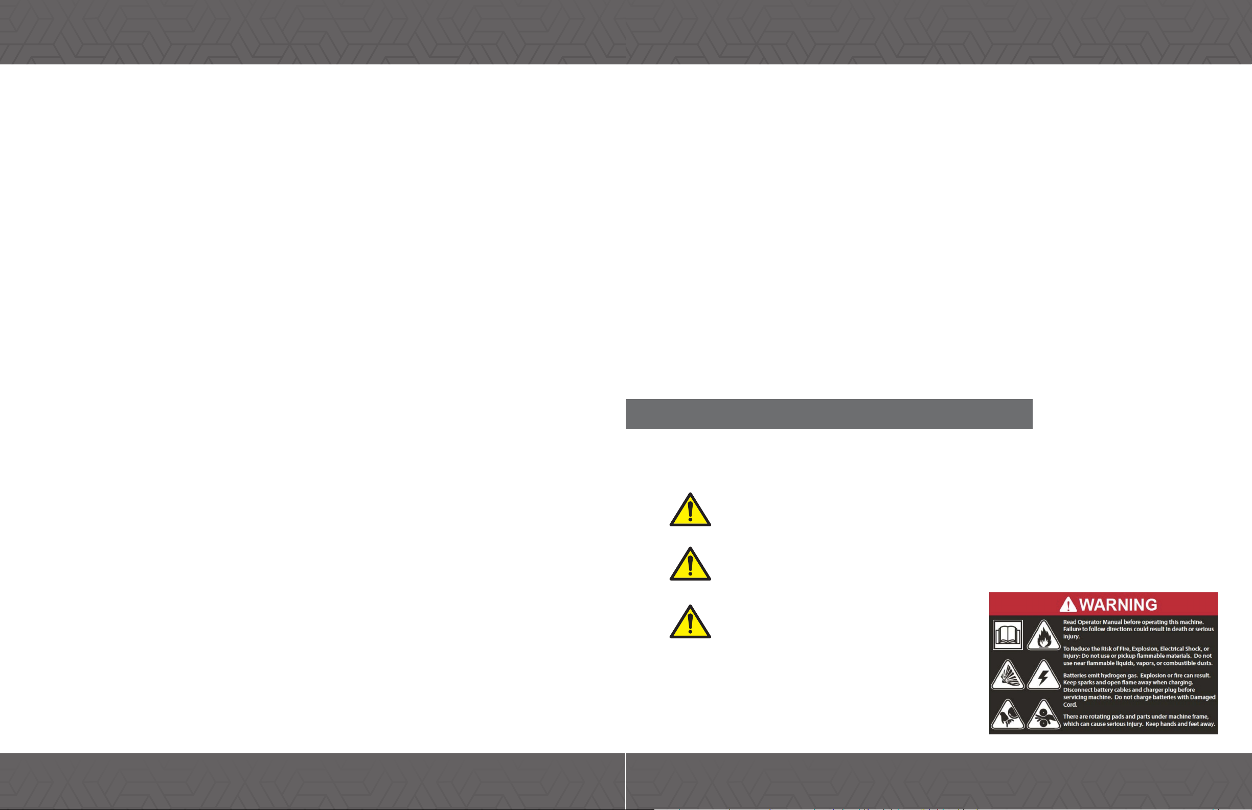
SAFETY SYMBOLS
These following safety symbols appear on the machine and in this manual to alert the operator of
potential safety hazards. Read them carefully and understand their meaning. Replace labels if they are
missing or become damaged or illegible.
• Do not use incompatible battery chargers as this may damage battery packs and potentially cause a
re hazard.
• Inspect charger cord regularly for damage.
• Keep work area well ventilated.
• Avoid contact with battery acid.
• Keep all metal objects o batteries.
• Do not power spray or hose o machine.
• Use a hoist or adequate assistance when lifting batteries.
• Battery installation must be done by trained personnel.
• Wear personal protection equipment as needed and where recommended in this manual.
DANGER: The signal word DANGER indicates a hazardous situation which, if not avoided according
to the instruction found in this Operator Manual or on your machine, will result in death or serious
bodily injury.
WARNING: The signal word WARNING indicates a hazardous situation which, if not avoided
according to the instruction found in this Operator Manual or on your machine, could result in
death or serious bodily injury.
CAUTION: The signal word CAUTION indicates a
hazardous situation which, if not avoided according
to the instruction found in this Operator Manual or
on your machine, could result in minor or moderate
injury or damage to your engine or property.
SAFETY INSTRUCTIONS SAFETY INSTRUCTIONS

8 9
MACHINE UNPACKING
MACHINE OPERATION
Carefully check machine for signs of damage. Report damages at once to carrier. To uncrate the machine,
remove straps, wheel blocks and shipping brackets. Using the supplied ramp carefully back the machine o
the pallet. Make sure scrub head is in the raised position.
ATTENTION: Do not remove machine from pallet without using ramp, machine damage may occur.
WARNING: Fire or explosion hazard: Do not operate the machine close to or in the place
where there is ammable liquid, air or dust.
FOR SAFETY: Please do not operate this machine before reading and understanding the operator
manual.
Pre-operational checklist:
Clean the dust on the ground.
Check the battery indicator to be sure the battery is charged.
Check the abrasion conditions of the pad or brush.
Check the condition of the squeegee and adjust and/or replace if necessary.
Conrm that the recovery tank is empty and is equipped with a clean oating lter screen.
Check the conditions of the skirt section of the brush head.
MACHINE COMPONENTS & SPECS
1. KEYSWITCH
2. BATTERY INDICATOR
3. VACUUM SWITCH
4. BRUSH SWITCH
5. WATER CONTROL
6. SPEED CONTROL
7. SQUEEGEE PEDAL
8. FORWARD/REVERSE
9. SQUEEGEE
10. SOLUTION FILL
11. RECOVERY TANK
MACHINE SPECIFICATIONS
Voltage
Battery Capacity
Cleaning Width
Squeegee Width
Cleaning Eciency
Brush Motor
Vacuum Motor
Solution Capacity
Recovery Capacity
Weight
Dimensions (LxWxH)
24 Volt
100 Ah
20”
30”
24,000 sq ft/hr
650W
500W
18.5 Gallons
20 Gallons
460 lbs.
49” x 20” x 47”
To operate machine:
1. Switch the key of the main power supply to the position of ON(I).
2. Pull down the squeegee lifting rod to lower the squeegee to the ground.
3. Step on the brush head lifting pedal or press the Brush Switch to lower the brush head.
5. Press the vacuum motor switch (20” Model only).
6. Motor drive models: adjust the speed control knob to the desired cleaning speed.
7. Each cleaning path should overlap by 2in.
8. Keep the machine moving to avoid damage to the oor.
9. If there is a drag mark on the ground after the squeegee, lift and clean the squeegee.
10. Do not operate the machine on the slope with a slope over 5% (3°).
11. Use the “double scrub” method to clean extremely dirty areas. Lift up the squeegee and scrub the
oor back and forth, the re-lower the squeegee for waste recovery.
12. Replace or rotate the pad or brush as required.
13. Observe the power consumption of the battery indicator.
14. Observe the amount of solution in the solution tank. In traditional scrubbing, the typical con-
sumption is about 2.5 gallons every 10 minutes.
15. When the solution in the solution tank is empty, empty the recovery tank rst, then rell the
solution tank.
16. When nished cleaning, stop and place the machine on the level ground, turn o and take key.
17. After cleaning, preform the daily maintenance procedures.

10 11
MACHINE MAINTENANCE
Follow the daily, weekly and monthly maintenance procedures to keep the machine in good condition.
WARNING: Electric shock hazard. Please rstly disconnect the battery wiring before maintaining
the machine.
DAILY MAINTENANCE:
1. Drain and clean the wastewater tank.
2. Dismantle and ush the oating lter screen in the wastewater tank.
3. Drain the clean water tank and ush the water tank with hot water of no higher than 140F as required.
4. Dismantle the scouring pad/brush for cleaning. If there is any abrasion, overturn or replace the scouring
pad.
5. Wipe the squeegee adhesive tape. Place the squeegee component in the rising position to avoid damage to
adhesive tape.
6. Check the abrasion conditions of the scraper edge of the squeegee adhesive tape. If there is any wear
and tear, exchange two sides of the adhesive tape.
7. Use multi-purpose detergent and wet cloth to wipe the machine. For safety: please do not spray this
machine with high pressure or ush this machine with water pipe when cleaning the machine to avoid failure
of electronic component.
8. Check the abrasion conditions of the skirt side of the brush head and replace it if there is any wear and
tear or damage.
9. Charge the battery. To prolong the life of the battery and ensure the optimum eciency of the machine,
the battery must be charged after the use time of the machine exceeds 30min.
MONTHLY MAINTENANCE:
1. Dismantle the lter of the clean water tank from the bottom of the machine and clean the lter screen.
Ensure the clean water tank is emptied before dismantling the lter.
2. Clean the top of the battery to prevent electrode corrosion (refer to [Battery Maintenance]).
3. Check whether the battery wiring is loose.
4. Check and clean the cover seal of the wastewater tank and replace it if there is any damage.
5. Spray the silica gel dry lubricant on all pivots and wheels and cover a layer of water-proof lubricating oil
to ensure smooth operation of wheels and pivots.
6. Check whether the nuts and bolts on the machine are loose.
7. Check whether the machine leaks.
QUARTERLY MAINTENANCE:
Please contact your local service center every 250 hours for a machine inspection of brush and drive motors.
WARNING: Electric shock hazard. Please rstly disconnect the battery wiring before maintaining
the machine.
TROUBLE SHOOTING GUIDE
The Machine cannot be
operated
The battery has no power
The batter fails
The battery wiring is loose
The main fuse blows out
Charge the battery
Replace the battery
Fasten the battery wiring
Replace the fuse
Problem Reason Solution
The brush motor does not
work
The vacuum motor does
not work
The brush head rises up from the ground
The battery coulomb-meter is locked and not started
The brush switch fails
The brush motor fails
The squeegee rises up from the ground
The fuse of the vacuum motor blows out
The vacuum motor or wiring fails
The carbon brush of the motor is worn
The lter or solution pipe of the clean water tank is blocked
The speed of the ow control knob is set too low
The screw of the control knob is loosened
Lower down the brush head
Charge the battery
Please contact the service center
Lower down the squeegee
Replace the fuse
Please contact the service center
Clean the lter of the clean water tank
Adjust the water control knob
Little or no water
ows out Lubricate the knob and then fasten
the screw
The waste water
recovery rate is low
The waste water tank is full
The water suction pipe is blocked
The sealing strip of the waste water tank is damaged
The vacuum motor fails
Drain the waste water tank
Remove the blocked scraps
Replace the sealing stripe
Please contact with the service center
Replace the battery
Repair or replace the charger
The operating time is
short
The battery is damaged
The battery charging fails

12 13
WIRING DIAGRAM/SCHEMATIC DX20T
Link to Wiring Schematic PDF le on ONYX Website Support Page:
https://www.onyxsolutions.store/support
WIRING DIAGRAM/SCHEMATIC DX20
M
+
-+
-
M
M
KeySwitch
BK
RD
12V12V
RD
YL
ColorCodes:
B
K=Black WT=White
R
D=Red BN=Brown
Y
L=Ye llow GY=Gray
GN =Green BL=Blue
P
R= Purple PK = Pink
OG =Orange CY =Cyan
N
ote: Colors mayVary
10AThermal
CircuitBreaker
(Front Panel)
B
rush Switch
(Front Panel)
V
ac Switch
(Squeegee Lift)
V
ac
M
otor
B
rush
M
otor
T
raction
M
otor
B
attery/Hour
M
eter
Charging Port
Speed Control
Controller (Diagram)
FUSE
80A
BL
BN
PR
BL
PR
-
+
J-18
J-5
J-4
J-3
J-13
B+
B-
J-17
J-6
J-14
u
A3Dctr
RD
PK
RD
RD
RD
RD
RD
RDRD
RD
RD
BK
BN
BK
BK
BK
BL
GN
BK
YL
BL
GY
BK
BK
BK BK
BrushRelay (Switch)
Solenoid
W
ater Valve
B
rush Relay(Coil)
Vac Relay(Coil)
Vac Relay(Switch)
4
0A Therma l
CircuitBreaker
(Front Panel)
RD
F
orward
B
ackward
GN
BK
WT
WT
WT
SmallRelay
BL
BN
OG
Link to Wiring Schematic PDF le on ONYX Website Support Page:
https://www.onyxsolutions.store/support

onyxsolutions.com
Other manuals for DX20
1
This manual suits for next models
1
Table of contents
Other Onyx Scrubber manuals