Opel Vauxhall VCI User manual

Opel-Vauxhall-VCI
en operating instruction

1 689 989 451 2019-07-01
| Opel Automobile GmbH
2 | Opel-Vauxhall-VCI |en
Content English
1. Symbols used 1
1.1 In the documentation 1
1.1.1 Warning notices – structure and explanation 1
1.1.2 Symbols – designation and explanation 1
1.2 On the product 1
2. User instructions 2
2.1 Intended users 2
2.2 FCC Compliance (USA) 2
2.3 Open-source software (OSS) 2
2.4 Electromagnetic compatibility (EMC) 2
2.5 Range of application 2
2.6 Wireless link (Bluetooth and WLAN) 2
2.7 Other applicable documents 4
3. Safety instructions 4
4. Product description 4
4.1 Intended use 4
4.2 Scope of delivery 4
4.3 Opel-Vauxhall-VCI Ports and control elements 5
4.4 Universal Serial Bus (USB) Port 5
4.5 Wireless Local Area Network (WLAN) 5
4.6 Ethernet 5
4.7 Additional Opel-Vauxhall-VCI Features 5
4.7.1 Data transfer 5
4.7.2 Power Supply 6
4.7.3 LED status display 6
4.8 VCI Manager program 6
4.9 System requirements 6
5. Operation 7
5.1 Installation notes 7
5.2 Installing the VCI Manager software 7
5.3 Setting up the diagnostic device hardware 7
5.3.1 Identifying your diagnostic device 7
5.3.2 Updating the diagnostic device software 7
5.3.3 Configuring the Opel-Vauxhall-VCI using VCI
Manager 8
5.3.4 Checking the computer and Opel-Vauxhall-VCI
software versions 8
5.4 Setting up wireless communications 9
5.4.1 Activating the WLAN link via an access point 9
5.4.2 Enabling point-to-point wireless communication
10
5.4.3 Setting to factory default 11
5.5 Connecting the diagnostic device to a vehicle
11
5.6 Resetting the Opel-Vauxhall-VCI 12
5.7 Loopback self-test 12
6. Troubleshooting 13
6.1 Opel-Vauxhall-VCI error LED lights after power
On 13
6.2 The Opel-Vauxhall-VCI fails to power up 13
6.3 "Vehicle LED is flashing red 13
6.4 Opel-Vauxhall-VCI speaker is beeping 13
6.5 Opel-Vauxhall-VCI turns off immediately
when disconnected from the vehicle during a
diagnostic session 14
6.6 "Checkmark" LED flashing on the Opel-Vauxhall-
VCI 14
6.7 Suspected defective diagnostic connection
cable 14
6.8 Wireless communication with network
unsuccessful using DWA131 E1 dongle 15
6.9 VCI Manager displays yellow icon over Opel-
Vauxhall-VCI after previous use 15
6.10 Computer application is unable to communicate
with the Opel-Vauxhall-VCI over USB 15
6.11 Computer application is unable to communicate
with Opel-Vauxhall-VCI over wireless or Ethernet
16
7. Cleaning and Maintenance 16
7.1 Restoring the system software on the Opel-
Vauxhall-VCI (Recovery) 16
7.2 Spare and wearing parts 16
8. Decommissioning 17
8.1 Temporary shutdown 17
8.2 Changing location 17
8.3 Disposal 17
9. Glossary 17
10. Technical data 18

1 689 989 4512019-07-01 |Opel Automobile GmbH
Symbols used | Opel-Vauxhall-VCI | 1 en
1.2 On the product
!Observe all warning signs on products and
ensure they remain legible.
Icon Meaning
EU declaration of conformity
US declaration of conformity
Certification for the Russian Federation
Certification for Ukraine
Certification for Australia, New Zealand
Certification for Morocco
Certification for South Korea
Use of the Opel-Vauxhall-VCI and and re-
cording of diagnostic data while driving
may only be performed by trained and in-
structed employees of the service work-
shop.
Attention: general warning sign indicating
danger. Before commissioning, connecting
and operating Bosch products, it is abso-
lutely essential to read the entire opera-
ting instructions carefully, especially the
safety instructions.
Dispose of used electrical and electro-
nic devices, including cables, accesso-
ries and batteries, separately from house-
hold waste.
China RoHS (environmental protection)
1. Symbols used
1.1 In the documentation
1.1.1 Warning notices – structure and expla-
nation
Warnings warn of dangers to the user or people
in the vicinity. Warning notices also indicate
the consequences of the danger as well as
preventive action. Warnings have the following
structure:
Warning
symbol
SIGNAL WORD – nature and source
of danger!
Consequences of the danger in the
event of failure to take action and
observe notices given.
¶Actions and instructions to pre-
vent the danger.
The signal word indicates the likelihood of occur-
rence and the severity of the danger in the event of
non-observance:
Signal word Likelihood of
occurrence
Severity of danger
with
non-observance
DANGER Immediate threat
of danger
Death or serious
injury
WARNING Possible impend-
ing danger
Death or serious
injury
CAUTION Possible dan-
gerous
situation
Minor
injury
1.1.2 Symbols – designation and explanation
Icon Designation Meaning
!Attention Warning of possible damage.
iInformation Practical hints and other useful
information.
1.
2.
Multiple-step
instruction
Procedure involving several ac-
tions.
eSingle-step
instruction
Procedure involving only one
action.
Intermediate
result
An instruction produces a visible
intermediate result.
"Final result The final result becomes ap-
parent on completion of the in-
struction.

1 689 989 451 2019-07-01
| Opel Automobile GmbH
2 | Opel-Vauxhall-VCI | User instructionsen
2. User instructions
Before commissioning, connecting and operat-
ing this product, it is absolutely essential that
the operating instructions/owner’s manual
and, in particular, the safety instructions are
studied carefully. By doing so you can eradicate
any uncertainties about this product and any
associated safety risks upfront; something which
is in the interests of your own safety and will ul-
timately help avoid damage to the device. When
this product is handed over to another person,
not only the operating instructions but also the
safety instructions and information on its desig-
nated use must be handed over to the person.
2.1 Intended users
The product may be used by skilled and instruc-
ted personnel only. Personnel scheduled to be
trained, familiarized, instructed or to take part
in a general training course may only work with
the product under the supervision of an experi-
enced person.
All work on electrical devices must be carried
out by individuals with sufficient knowledge and
experience in the fields of electrical and hydraulic
equipment.
2.2 FCC Compliance (USA)
Opel-Vauxhall-VCI complies with the require-
ments of Section 15 of the FCC Rules. The follo-
wing conditions apply regarding operation:
ROpel-Vauxhall-VCI must not cause any harmful
disruptions;
ROpel-Vauxhall-VCI must permit reception of
interference, including interference that can
cause unwanted operation.
The Opel-Vauxhall-VCI was tested and com-
plies with the limits for a ClassA digital device
as defined in Part15 of the FCC regulations.
These limits are designed to provide reasonable
protection against harmful interference when
the equipment is operated in a commercial
environment. Opel-Vauxhall-VCI may generate,
use and emit energy at radio frequencies that
can disrupt radio communication if installed
improperly or used in a manner inconsistent
with the operating instructions. Operation of
Opel-Vauxhall-VCI in a residential area is likely
to cause harmful interference, in which case the
user will be required to correct the interference
at his or her expense.
iAll changes or modificati-
on to the Opel-Vauxhall-VCI that
are not expressly allowed by
Opel Automobile GmbH
can result is loss of permission to operate
Opel-Vauxhall-VCI.
2.3 Open-source software (OSS)
For an overview of the open-source software
licenses, see "C:\PROGRAM FILES (X86)\
BOSCH\VTX-VCI\VCI SOFTWARE (6531-BOSCH)\
LEGAL".
2.4 Electromagnetic compatibility
(EMC)
The Opel-Vauxhall-VCI satisfies the requirements
of the EMC directive 2014/30/EU.
iOpel-Vauxhall-VCI is a class/category A
product in accordance withEN 61 326. The
Opel-Vauxhall-VCI may cause high-frequency
household interference (radio interference)
so that interference suppression may be
necessary. In such cases, the operator may
be required to take appropriate action.
2.5 Range of application
The Opel-Vauxhall-VCI is intended for indoor use
only.
RDo not expose Opel-Vauxhall-VCI to rain
or moisture and prevent the formation of
condensation.
RDegree of contamination 2, keep area around
Opel-Vauxhall-VCI clean.
2.6 Wireless link (Bluetooth and
WLAN)
!Opel-Vauxhall-VCI users are responsible for
compliance with the applicable directives and
restrictions in the country concerned.

1 689 989 4512019-07-01 |Opel Automobile GmbH
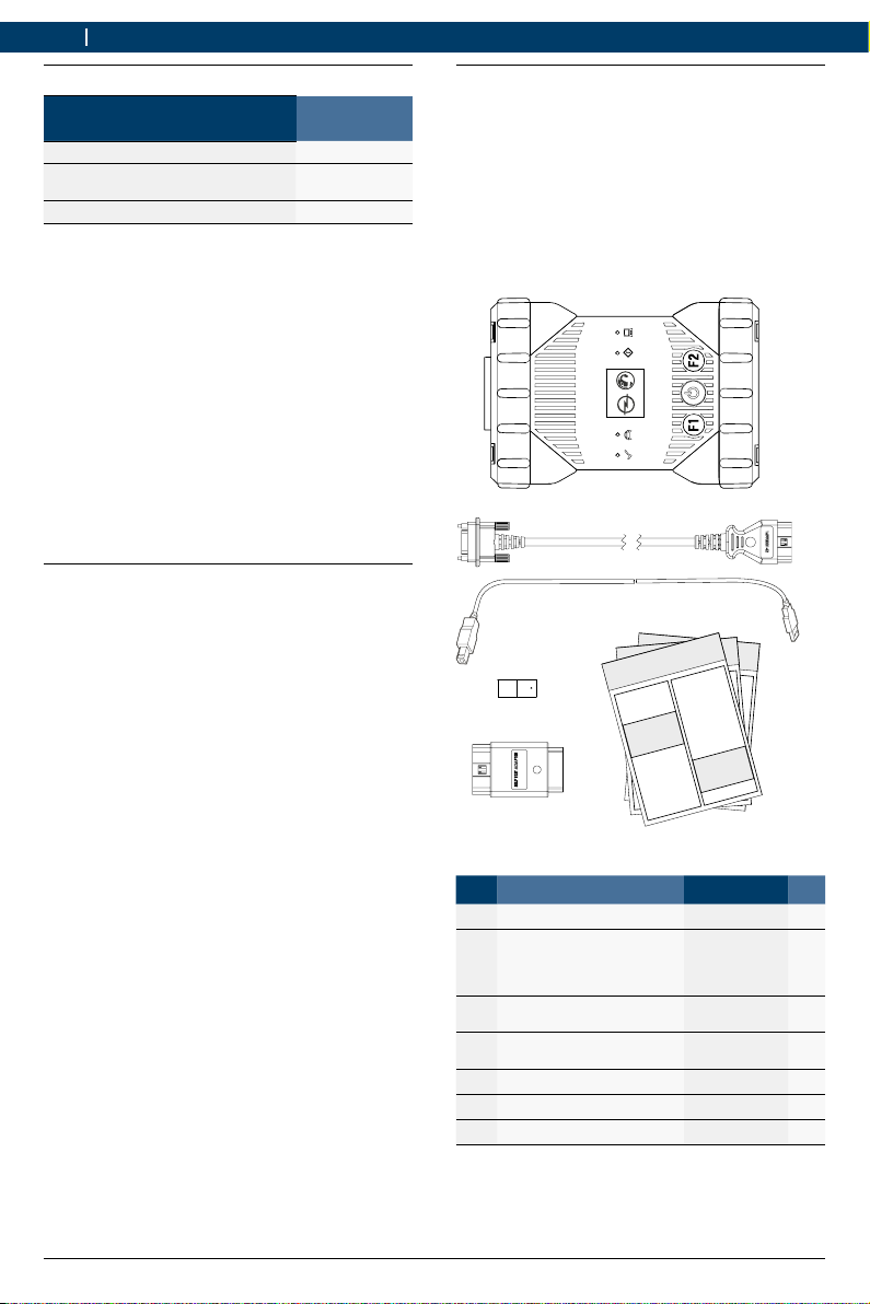
User instructions | Opel-Vauxhall-VCI | 3 en
Important information on WLAN and Bluetooth
WLAN (Wireless Local Area Network) is the term
used to describe a wireless local network. Blue-
tooth and WLAN provide a radio link on the free
2.4GHz ISM band (ISM: Industrial, Scientific,
Medical). This frequency range is subject to
state legislation, can however be used without a
license in most countries. Consequently a large
number of applications and devices employ this
frequency band for transmission. This can result
in frequency interference and faults.
Depending on ambient conditions, the radio link
may deteriorate, e.g. in the case of Bluetooth
links, cordless telephones, radio-controlled
thermometers, radio-controlled garage door
openers, radio-controlled light switches or ra-
dio-controlled alarm systems.
iBluetooth can cause bandwidth collapse in
the WLAN network. The antennas of Blue-
tooth and WLAN devices should be at least
30centimeters apart. Use the USB extension
cable (special accessory) to maintain a dis-
tance between the Bluetooth USB adapter on
the computer and the WLAN antenna.
iExtreme caution is to be taken if wearing
pacemakers or other vital electronic devices
when using wireless systems, as proper func-
tioning of these items could be impaired.
Pay attention to the following to ensure the best
possible connection:
¶The radio signal always tries to find the most
direct path. When setting up the computer
and access point, make sure there are as few
obstacles as possible (e.g. steel doors and
concrete walls) which could interfere with
the signal from and to the Opel-Vauxhall-VCI.
¶Inside buildings, the range of the WLAN /
Bluetooth is also greatly influenced by the
construction materials used. Conventional
masonry, wooden walls and various types
of dry construction wall scarcely impair the
propagation of radio waves. Thin gypsum
walls are however problematic, as consider-
able amounts of moisture may accumulate in
the gypsum and result in the absorption of
radio signals. Metal walls and concrete (in
particular reinforced concrete) largely block
out radio waves. Cellar ceilings are often
impenetrable. Generally speaking, walls with
a lot of installed metal (e.g. pipes, cables)
obstruct radio waves.
¶Radio reception is also impeded by large me-
tal objects such as radiators and window fra-
mes as well as active sources of interference
such as radio telephones, motion detectors
and microwave ovens.
¶Human beings are also an obstacle to wire-
less transmission. It must therefore always
be ensured that no-one stands between the
transmitter and receiver.
¶We advise having the network infrastruc-
ture installed and maintained by a network
specialist.
¶When using a WLAN connection, keep the
SSID and the codes for the wireless link in a
safe place. Make sure these data are readily
to hand in case faults occur.
¶When commissioning, we recommend that you
tour the site thoroughly: Determine where in
your building Opel-Vauxhall-VCI functions and
where the limits for wireless transmission are
located.
¶The wireless link is affected by weather condi-
tions. The reception signal may therefore vary.
¶Please contact your network specialist for any
queries.
¶In the event of problems with the radio link,
the USB link can be activated and used ins-
tead of the radio connection.

1 689 989 451 2019-07-01
| Opel Automobile GmbH
4 | Opel-Vauxhall-VCI | Safety instructionsen
4.2 Scope of delivery
The Opel-Vauxhall-VCI Base Kit includes con-
necting cables and hardware needed to transfer
data and reprogram ECUs on vehicles through
the diagnostic connector.
iThe scope of delivery depends on the prod-
uct variant ordered as well as the optional
accessories ordered, and can deviate from the
following list.
2
3
4
6
1
DIAGNOSI
5
Item Kit Component Part number
1 VCI system tester 1 699 200 790 1
2 Diagnostic connection
cable
(data transmission to
J1962)
1 699 200 366 1
3 USB connecting cable A
to B, 3m
F00K.108.653 1
4 Ethernet connecting cab-
le 1.5m
1 684 465 811 1
5 Wireless WiFi USB stick – 2
6 Test adapter (self-test)* 1 699 200 154 1
7 Applicable documentation – 3
* Optional accessories
2.7 Other applicable documents
Designation Document
number
Quick Start Guide 1 689 989 452
Important information and safety in-
structions
1 689 989 453
Specifications – WLAN USB adapter 1 689 989 305
3. Safety instructions
!These operating instructions are intended
to ensure easy and safe setup and use of
the Opel-Vauxhall-VCI. Read these oper-
ating instructions and other applicable
documentation carefully before using the
Opel-Vauxhall-VCI and the software.
4. Product description
4.1 Intended use
!If the Opel-Vauxhall-VCI and the scope of
delivery are operated contrary to the way
specified by the manufacturer in the oper-
ating instructions, the protection provided
by the Opel-Vauxhall-VCI and the supplied
accessories may be compromised.
The Opel-Vauxhall-VCI is a measuring instrument
used by professional technicians as an aid in
diagnosing and repairing automotive electrical
and electronic systems. Additionally, the software
application with Opel-Vauxhall-VCI can be used
to measure voltage levels, for example.

1 689 989 4512019-07-01 |Opel Automobile GmbH
Product description | Opel-Vauxhall-VCI | 5 en
4.3 Opel-Vauxhall-VCI Ports and cont-
rol elements
The Opel-Vauxhall-VCI has various keys and
standardized ports for operating the device and
connecting it to the vehicle electrical system and
workshop network. These connectors and cont-
rols are shown in the following illustrations.
1
2
43
3
5
67
Item Description
1 LED status display
2 Control keys
3 2x USB-A port
4 Port for diagnostic connection cable
5 USB-B port
6 WiFi Adapter
7 Ethernet Port
4.4 Universal Serial Bus (USB) Port
The Opel-Vauxhall-VCI has a fixed USB configura-
tion which cannot be changed. This ensures that
the Opel-Vauxhall-VCI can always be connect-
ed to a single computer running the software
"VCIManager" or the user software so you can
configure LAN or WLAN settings required by your
local network. In addition, it is important to note
that a USB connection is required to configure
the firmware on the Opel-Vauxhall-VCI, to pair
the computer with the Opel-Vauxhall-VCI and to
update the firmware.
4.5 Wireless Local Area Network
(WLAN)
During setup and configuration of the WLAN
connection (802.11b/g/n), the Opel-Vauxhall-VCI
must be connected via USB to a computer run-
ning the software "VCIManager" and be paired
with the computer.
4.6 Ethernet
During setup and configuration of the Ethernet
connection, the Opel-Vauxhall-VCI must be
connected via USB to a computer running the
software "VCIManager" and be paired with the
computer.
4.7 Additional Opel-Vauxhall-VCI
Features
4.7.1 Data transfer
The connection between the Opel-Vauxhall-VCI
and the vehicle electronics is established via the
26-pin diagnostic connection cable.

1 689 989 451 2019-07-01
| Opel Automobile GmbH
6 | Opel-Vauxhall-VCI | Product descriptionen
4.8 VCI Manager program
The "VCI Manager" program is a host compu-
ter application which runs on the Windows
operating system to configure and update
Opel-Vauxhall-VCI. The software "VCI Manager"
allows the configuration of VCI-to-host computer
communications and facilitates VCI firmware
updates.
4.9 System requirements
The Opel-Vauxhall-VCI is set up and updated
via the "VCIManager" software. VCIManager is
installed on a computer. The Opel-Vauxhall-VCI is
controlled in the corresponding user software.
iThe system requirements listed below refer to
use of the "VCI Manager" software. The user
software requirements may differ.
RWindows 7, Windows 8 or Windows 10 (32-
bit and 64-bit)
R100MB free hard disk space
R512MB RAM
R1GHz processor
R1 free USB ports
R1024x768 display resolution
4.7.2 Power Supply
The Opel-Vauxhall-VCI is designed for voltage to
be supplied from the vehicle via the diagnostic
connection cable. For data transfer or a sys-
tem update, the Opel-Vauxhall-VCI can also be
supplied with voltage from the USB port on a
computer.
iIf the is Opel-Vauxhall-VCI to be configured
for a wireless connection, the voltage must
be supplied via the USB connecting cable.
4.7.3 LED status display
Four light emitting diodes (LEDs) are located on
the front of the Opel-Vauxhall-VCI. The LED indi-
cators provide the following status information.
Icon Color
Status
LED Function
green Opel-Vauxhall-VCI without er-
rors
red Error occurred, perform a re-
set
green Opel-Vauxhall-VCI connected
to vehicle
Flashing
red
Not connected to external 12
or 24V power
off Opel-Vauxhall-VCI without er-
rors
red
Error occurred or
Opel-Vauxhall-VCI in reco-
very state
off Opel-Vauxhall-VCI not connec-
ted to a computer
Flashing
green
Opel-Vauxhall-VCI connected
to computer
off Opel-Vauxhall-VCI off
green Opel-Vauxhall-VCI on
yellow/
green
depending on user software
yellow/
green
depending on user software

1 689 989 4512019-07-01 |Opel Automobile GmbH
Operation | Opel-Vauxhall-VCI | 7 en
5. Operation
The following sections provide the information
needed to begin using the Opel-Vauxhall-VCI,
including installing the "VCI Manager" software,
updating the firmware on the device, configuring
connection methods, and communicating with
the vehicle.
5.1 Installation notes
iPlease follow the installation instructions for
the user software.
5.2 Installing the VCI Manager
software
The "VCI Manager" software must be installed
on the computer in order to configure, update
and run diagnostic applications targeted for the
computer. Initially you use the "VCI Manager"
software to set up the configuration of each
Opel-Vauxhall-VCI.
iVisit TIS2Web for OPEL-VAUXHALL VCI Mana-
ger software download.
5.3 Setting up the diagnostic de-
vice hardware
5.3.1 Identifying your diagnostic device
The rating plate is located on the back of
Opel-Vauxhall-VCI. The Opel-Vauxhall-VCI iden-
tification number has two parts: a manufactu-
ring code for traceability and a unique serial
number. The serial number is used to identify
Opel-Vauxhall-VCI in the "VCIManager" software.
You will need to refer to this serial number
when you are using VCI Manager to configure
Opel-Vauxhall-VCI and perform software up-
dates.
5.3.2 Updating the diagnostic device soft-
ware
Opel-Vauxhall-VCI is shipped from the factory
without firmware. Your first connection is to the
computer where you have installed the "VCIMa-
nager" software. You will need the USB connec-
ting cable to configure your Opel-Vauxhall-VCI
using VCI Manager.
Use the following procedure to update the firm-
ware on your VCI.
1. Start the "VCI Manager" program.
2. Connect the Opel-Vauxhall-VCI to your com-
puter using the USB connecting cable.
The Opel-Vauxhall-VCI will boot in Recove-
ry mode. (only in factory setup)
3. Choose the new Opel-Vauxhall-VCI from the
shown list.
The button <Verbinden> (Connect) will be
renamed to the button <Wiederherstellen>
(Recover). Your Opel-Vauxhall-VCI will be
displayed without the serial number when
initially connected to VCI Manager.
4. Press <Wiederherstellen>(Recover) to start
the update process.
!Do not unplug the Opel-Vauxhall-VCI from the
computer during the update process.
5. Click <Update starten> (Start update) to
install firmware on the Opel-Vauxhall-VCI.
6. Click <OK> to continue.
7. The update process will take about 5 minutes
to complete. Once the update process is com-
plete, the Opel-Vauxhall-VCI will automatically
reboot. Wait until you hear the beep from the
Opel-Vauxhall-VCI before proceeding to use
your Opel-Vauxhall-VCI.

1 689 989 451 2019-07-01
| Opel Automobile GmbH
8 | Opel-Vauxhall-VCI | Operationen
5.3.3 Configuring the Opel-Vauxhall-VCI
using VCI Manager
In order to configure the Opel-Vauxhall-VCI
to communicate on your network, you must
connect the Opel-Vauxhall-VCI, via USB, to
a computer running the "VCI Manager" soft-
ware. The VCI Manager icon displayed on the
Opel-Vauxhall-VCI will inform you of the commu-
nication method to be used when <Verbinden>
(Connect) is selected.
Icon Description
VCI Manager will connect to the
Opel-Vauxhall-VCI via USB
VCI Manager will connect to the
Opel-Vauxhall-VCI via Ethernet
VCI Manager will connect to the
Opel-Vauxhall-VCI via Wireless
Wireless Point-to-Point is not set up. Use
a USB connecting cable to connect the
Opel-Vauxhall-VCI to the computer to comple-
te setup.
Wireless adapters in the computer and in the
diagnostic device are incompatible with each
other.
VCI Manager is connected to the
Opel-Vauxhall-VCI
Use the following steps to configure your
Opel-Vauxhall-VCI.
1. Double-click the VCI Manager icon on your
desktop to launch the "VCIManager" soft-
ware.
2. Select Opel-Vauxhall-VCI in "VCI Explorer".
3. Click <Verbinden> (Connect) to connect to
the selected Opel-Vauxhall-VCI over USB.
"Opel-Vauxhall-VCI is displayed with a green
checkmark on your display, indicating that your
"VCI Manager" software is in control of this
Opel-Vauxhall-VCI.
4. Click <Details anzeigen> (Show de-
tails) to see details about the selected
Opel-Vauxhall-VCI.
iIf your Opel-Vauxhall-VCI is connected to
another networked computer, it will still be
detected by the VCI Manager, but will not be
available for connection.
iIf your Opel-Vauxhall-VCI is connected via
USB to your computer, the VCI Manager
functions on all tabs are available; if your
Opel-Vauxhall-VCI is not connected via
USB, the functions on the Network Setup
and Opel-Vauxhall-VCI Update tabs are not
available.
5.3.4 Checking the computer and
Opel-Vauxhall-VCI software versions
iEnsure, that the "VCI Manager" software
installed on your computer and the software
installed on the Opel-Vauxhall-VCI have
matching software versions in order for
Opel-Vauxhall-VCI to operate properly. Use
the following steps to check your software
versions.
1. Connect the Opel-Vauxhall-VCI to your com-
puter using the USB connecting cable.
2. Double-click the VCI Manager icon on your
desktop to launch the "VCIManager" soft-
ware.
3. Choose your Opel-Vauxhall-VCI in "VCI Ex-
plorer".
4. Click <Verbinden> (Connect) to connect to
the selected Opel-Vauxhall-VCI over USB.
5. Choose "Help" to see details about the soft-
ware versions.

1 689 989 4512019-07-01 |Opel Automobile GmbH
Operation | Opel-Vauxhall-VCI | 9 en
5.4 Setting up wireless communi-
cations
Opel-Vauxhall-VCI is capable of communicating
on your workshop network over Wireless. The
"Network Setup" tab in the "VCIManager" soft-
ware provides a number of functions used to
select and configure Opel-Vauxhall-VCI network
connection interfaces, including wireless access
and security settings.
iYou must be connected to the
Opel-Vauxhall-VCI via USB to access the set-
tings on the "Network Setup" tab. If you are
not connected via USB, the controls on the
"Network Setup" tab are disabled.
iThe Opel-Vauxhall-VCI supports the Point-to-
Point method for wireless communication.
Point-to-point
With the Point-to-Point Wireless Communication
method, the Opel-Vauxhall-VCI connects to your
computer directly using a USB wireless adapter.
Each of these methods are described in the
following sections.
5.4.1 Activating the WLAN link via an access
point
The Opel-Vauxhall-VCI can be configured to con-
nect via an access point. The following must be
prepared before configuring:
RAn IP address and subnet mask that can be
assigned to the Opel-Vauxhall-VCI (if the
existing LAN does not assign IP addresses
automatially)
RA wireless network access point SSID
(network name)
RNetwork security standard WPA2 enabled
RData encryption via TKIP or WEP (64-bit or
128-bit)
RWLAN password
The figure below shows several
Opel-Vauxhall-VCIs that are connected to a single
computer via a wirelss access point.
You use the following procedure to configure your
Opel-Vauxhall-VCI for a wirelss connection in your
network environment. Contact your IT administra-
tor before starting setup.
1. Double-click the VCI Manager icon on your
desktop to launch the "VCIManager" soft-
ware.
2. Plug the Opel-Vauxhall-VCI into an external
12V power source.
3. Plug the USB connecting cable into the
computer and Opel-Vauxhall-VCI and allow
Opel-Vauxhall-VCI to boot completely.

1 689 989 451 2019-07-01
| Opel Automobile GmbH
10 | Opel-Vauxhall-VCI | Operationen
4. Connect to your Opel-Vauxhall-VCI in the VCI
Manager software.
5. Select the "Network Setup" tab.
6. In the "Wireless (802.11)" tab, select the
option "Activate wireless interface"
The "IP address configuration" input field
beocmes active.
7. Select the option "Automatic assignment
of IP address" if your network assigns IP
addresses automatically.
iIf your network uses fixed IP addresses, your
IT administrator will assign the IP address
and subnet mask.
8. Select <Access Point >>.
9. Assign network name:
$If the network uses a hidden SSID or is not
within range, the network name can be
enter via the option "Enter network name
(SSID)" .
$If the network is within range, the net-
work can be selected via the option
"Select from list of available networks".
Press <Aktualisieren> (Update) to have
the Opel-Vauxhall-VCI search for available
WLAN signals.
10.After the network name has been entered,
continue with <Configurieren>(Configure).
11.Enter the security settings for the network and
select <Weiter> (Next).
12.Select <Ja> (Yes) to configure the
Opel-Vauxhall-VCI again, or <Nein> (No) to can-
cel the procedure.
13.Select the "Settings" tab and check that the
Opel-Vauxhall-VCI was configured correctly.
iBy disconnecting the USB connection, you
can check whether configuration was suc-
cessful.
14.Back up the settings for future changes.
5.4.2 Enabling point-to-point wireless com-
munication
The Opel-Vauxhall-VCI can be configured for
point-to-point wireless communication. The
following illustration shows a single diagnostic
device connected to a computer using point-to-
point wireless communication.
If you need to reconfigure Point-to-Point on your
Opel-Vauxhall-VCI, use the following procedure.
The steps presented below assume you are run-
ning the Windows7 operating system on your
computer. The steps may differ depending on
the operating system.
1. Plug the WLAN USB adapter into an available
USB port on your computer.
!Do not plug the wireless adapter into a USB hub.
2. Switch on your computer.
3. Connect the Opel-Vauxhall-VCI to your com-
puter via the USB connecting cable and allow
the Opel-Vauxhall-VCI to boot completely.
!Do not plug the Opel-Vauxhall-VCI USB
connecting cable into a USB hub.
4. Start the "VCI Manager" program.
iThe Point-to-Point connection is automatically
configured. Wireless communication will be
available when you are powered through the
DLC cable.

1 689 989 4512019-07-01 |Opel Automobile GmbH
Operation | Opel-Vauxhall-VCI | 11 en
If you have the need to reset your Point-to-Point
passphrase, you can use the following steps.
1. Click the Wireless Network icon in your
Windows taskbar.
A list of the available wireless networks in
range of your computer is displayed.
2. Choose "Open Network and Sharing Center".
3. Choose "Manage Wireless Networks" from
the left column.
4. Choose "Change adapter" menu and choose
VCI from the list.
5. Remove your stored Point-to-Point network.
The name will contain MTS6531 and the last
8 digits of Opel-Vauxhall-VCI serial number,
(MTS6531xxxxxxxx).
6. When you reconnect Opel-Vauxhall-VCI to the
computer using the USB connecting cable, a
new passphrase will be established.
5.4.3 Setting to factory default
Setting the Opel-Vauxhall-VCI to Factory Default
restores the Point-to-Point communication set-
tings to the point it had when it left the factory.
Any software upgrades that have been installed
to Opel-Vauxhall-VCI are still installed. When the
reset is finished, the VCI Manager software dis-
plays the "VCI Explorer" tab. All wireless access
point configurations will be lost.
1. Start the "VCI Manager" program.
2. Plug the Opel-Vauxhall-VCI into an external
12V power source.
3. Plug the USB connecting cable into the
computer and Opel-Vauxhall-VCI and allow
Opel-Vauxhall-VCI to boot completely.
4. Connect to your Opel-Vauxhall-VCI in the VCI
Manager software.
5. Select the "Network Setup" tab.
6. Click <Set Factory Default>.
"Opel-Vauxhall-VCI is set to Factory Default.
5.5 Connecting the diagnostic
device to a vehicle
Opel-Vauxhall-VCI Vehicle Communication Inter-
face kit contains a diagnostic connection cable
that connects Opel-Vauxhall-VCI to the vehicle’s
SAE J1962 Data Link Connector (DLC).
Refer to the electrical wiring diagram for the
vehicle you are testing to determine the location
of the DLC on the vehicle.
1. Connect the 26-pin end of the diag-
nostic connection cable to the top of
Opel-Vauxhall-VCI, then tighten the screws.
2. Connect the 16-pin end of the diagnostic
connection cable to the vehicle DLC.
Powering the diagnostic device
Opel-Vauxhall-VCI is powered by the vehicle’s 12
or 24-volt battery.
CAUTION – Non-approved Acces-
sories - Malfunction
Possible risk of personal injury
¶Non-Bosch cables are not
approved for use with this equip-
ment, including a non-Bosch
USB connecting cable.

1 689 989 451 2019-07-01
| Opel Automobile GmbH
12 | Opel-Vauxhall-VCI | Operationen
CAUTION – Cables - Overload
Possible risk of personal injury
¶Make sure that any cable
connected to a high current
capable power source, such
as a 12-volt automotive bat-
tery, is in good condition. The
Opel-Vauxhall-VCI is protected
by its own internal protection
device. A fault in the cable itself,
especially a power to ground
short, is capable of creating a
hazardous situation that can
cause personal injury.
CAUTION – Loopback Self-Test
Adapter - Overload
Possible risk of personal injury
¶Do not apply power to
Opel-Vauxhall-VCI through the
self-test adapter barrel connec-
tor unless the circuit is protec-
ted by a fuse, circuit breaker, or
current-limited power supply.
The fuse, circuit breaker, or cur-
rent-limited power supply must
be set to no more than 3 amps.
5.6 Resetting the Opel-Vauxhall-VCI
1. Disconnect the voltage supply from the
Opel-Vauxhall-VCI.
2. Wait at least 20 seconds.
3. Reattach the voltage supply to the
Opel-Vauxhall-VCI.
5.7 Loopback self-test
With the self-test adapter you can conduct a lo-
opback self-test of the Opel-Vauxhall-VCI. using
the following steps.
1. Connect the diagnostic connection cable to
the Opel-Vauxhall-VCI.
2. Connect the self-test adapter to the vehicle
end of the diagnostic connection cable.
3. Power the self-test adapter either via a vehic-
le connection or a 12-V power adapter.
4. Start VCI Manager and connect the
Opel-Vauxhall-VCI.
5. In VCI Manager, choose "Help".
6. Press <Aktualisieren> (Update) to have the
search for available WLAN signals.

1 689 989 4512019-07-01 |Opel Automobile GmbH
Troubleshooting | Opel-Vauxhall-VCI | 13 en
6. Troubleshooting
This section is intended to help you get back
on track if the Opel-Vauxhall-VCI appears to be
operating abnormally. If the error is not elimi-
nated by the indicated remedy, it is necessary to
contact Service.
6.1 Opel-Vauxhall-VCI error LED
lights after power On
Recommendations
1. Power down the Opel-Vauxhall-VCI and verify
that the same problem exists when you pow-
er up again.
2. Connect the Opel-Vauxhall-VCI to a com-
puter using USB and perform the recovery
procedure.
6.2 The Opel-Vauxhall-VCI fails to
power up
Opel-Vauxhall-VCI should power up as soon as
external power is applied. If Opel-Vauxhall-VCI
does not turn on, first check the cable connec-
tions. Try supplying power to Opel-Vauxhall-VCI
from two different power sources – the vehicle
DLC and the USB connector.
Recommendations
¶Check that the cables are securely attached
to the Opel-Vauxhall-VCI and the connector
pins are clean.
$While the diagnostic device is connected
to the vehicle DLC, try powering from the
USB connector.
$While the diagnostic device is connected
to USB, try powering from the vehicle DLC.
6.3 "Vehicle LED is flashing red
If the Opel-Vauxhall-VCI does not detect 12V
on Pin 16 of the diagnostic connection cab-
le, Opel-Vauxhall-VCI will inform the user by
automatically turning on and flashing the Ve-
hicle LED red. This condition might be seen if
Opel-Vauxhall-VCI is only powered by a 5-V USB
connection or if the diagnostic connection cable
has accidently been displaced from the vehicle
Data Link Connector and is powered from the
backup capacitor. When Opel-Vauxhall-VCI de-
tects 12V on Pin 16, the Vehicle LED will stop
flashing red.
Recommendations
1. Ensure that 12V is applied to Pin 16 of the
diagnostic connection cable.
2. Ensure ground on J1962 pin 5 is good.
6.4 Opel-Vauxhall-VCI speaker is
beeping
If Opel-Vauxhall-VCI is performing diagnostic
services for the computer and does not detect
12V on Pin 16 of the diagnostic connection
cable, Opel-Vauxhall-VCI will inform the user
of the loss of power by beeping the spea-
ker. Opel-Vauxhall-VCI will continue to beep
until the backup capacitor is drained. When
Opel-Vauxhall-VCI detects 12V on Pin 16, the
speaker will stop beeping.
Recommendations
¶Ensure that 12V is applied to Pin 16 of the
diagnostic connection cable during diagnostic
sessions.

1 689 989 451 2019-07-01
| Opel Automobile GmbH
14 | Opel-Vauxhall-VCI | Troubleshootingen
6.5 Opel-Vauxhall-VCI turns off
immediately when disconnec-
ted from the vehicle during a
diagnostic session
If Opel-Vauxhall-VCI does not remain on during
cranking or DLC disconnect, there may be a
problem charging the internal capacitor.
The Opel-Vauxhall-VCI should remain powe-
red up if power is lost during engine cranking
or after it is disconnected from power (ve-
hicle DLC) during a diagnostic session. The
Opel-Vauxhall-VCI speaker will beep to notify
the user that power has been lost unexpectedly
during the diagnostic session.
Recommendations
1. Check for 12V power supply at the vehicle
DLC.
2. Ensure that the Opel-Vauxhall-VCI has been
connected to the vehicle DLC for at least 90
seconds to charge the internal capacitor.
6.6 "Checkmark" LED flashing on
the Opel-Vauxhall-VCI
If the internal temperature of Opel-Vauxhall-VCI
has exceeded the maximum limit,
Opel-Vauxhall-VCI will automatically turn off the
wireless adapter. This will be visible to the user
by the Checkmark LED flashing. When the inter-
nal temperature of Opel-Vauxhall-VCI lowers to
an acceptable value, the wireless adapter will be
re-enabled for wireless communication.
Recommendations
¶Move Opel-Vauxhall-VCI to a cooler location
near the vehicle.
6.7 Suspected defective diagnostic
connection cable
If you suspect a defective diagnostic connection
cable, you should perform the cable test from
the VCI Manager. The "VCI Manager" software
supports a cable test with the use of the self-
test adapter. The cable test will suggest whether
or not the diagnostic connection cable is defec-
tive. The self-test adapter used for the test is not
intended to be used for vehicle communication.
The following steps can be used to perform the
cable test.
1. Connect the diagnostic connection cable to
the Opel-Vauxhall-VCI.
2. Connect the self-test adapter to the vehicle
end of the diagnostic connection cable.
3. Power the self-test adapter either via a vehic-
le connection or a 12-V power adapter.
4. Start VCI Manager and connect the
Opel-Vauxhall-VCI.
5. In VCI Manager, choose "Help".
6. Enter the security settings for the network
and select <Weiter> (Next).
"The "VCI Manager" software will run a series
of tests on the diagnostic connection cable.
The results will be displayed as PASS or FAIL.

1 689 989 4512019-07-01 |Opel Automobile GmbH
Troubleshooting | Opel-Vauxhall-VCI | 15 en
6.10 Computer application is un-
able to communicate with the
Opel-Vauxhall-VCI over USB
The "VCI Manager" software must be installed
on the computer, and Opel-Vauxhall-VCI must
be powered up before it will communicate.
Opel-Vauxhall-VCI must be configured through
USB before it will communicate using any other
connection types.
Recommendations
If other applications including the VCI Manager
are able to connect to Opel-Vauxhall-VCI then:
¶Check the Windows Firewall settings to see if
the application is being blocked.
If all installed applications are unable to commu-
nicate with Opel-Vauxhall-VCI then:
1. Connect Opel-Vauxhall-VCI to the compu-
ter using USB, but do not connect it to the
vehicle.
!Do not plug the Opel-Vauxhall-VCI USB
connecting cable into a USB hub.
2. Verify that the USB connecting cables are
securely attached and Opel-Vauxhall-VCI has
completed its power up sequence.
3. Start the "VCI Manager" program.
4. Does VCI Manager detect the
Opel-Vauxhall-VCI?
If "No", then:
$Try a different USB connecting cable / port
on the computer.
$Check the Windows Firewall to see if the
VCI Manager is blocked.
$Check that the Opel-Vauxhall-VCI USB
connection is detected by Windows.
6.8 Wireless communication with
network unsuccessful using
DWA131 E1 dongle
The D-Link DWA131 E1 dongle is not intended to
be used for computer wireless communication
to a network. The DWA131 E1 dongle is only
intended to be used with Opel-Vauxhall-VCI for
Point-to-Point communication or Infrastructure
wireless communication.
Recommendations
1. Make sure you do not have two D-Link wire-
less dongles connected to the computer.
2. Make sure you are not trying to connect the
computer to your dealership network using
the DWA131 E1 dongle.
6.9 VCI Manager displays yellow
icon over Opel-Vauxhall-VCI
after previous use
There may be instances when Windows does
not recognize the installation of the DWA131
E1 wireless adapter. In these cases, Windows
may create a new wireless profile instead
of using the existing one already stored on
the computer. The yellow icon displayed
over your Opel-Vauxhall-VCI instructs you to
plug in the USB connecting cable between
Opel-Vauxhall-VCI and the computer.
Recommendations
¶Unplug and then re-install your wireless
adapter. Windows will attempt to recognize
the wireless adapter. If successful, the yellow
icon will disappear and Opel-Vauxhall-VCI will
be ready for wireless Point-to-Point commu-
nication.

1 689 989 451 2019-07-01
| Opel Automobile GmbH
16 | Opel-Vauxhall-VCI | Cleaning and Maintenanceen
6.11 Computer application is un-
able to communicate with
Opel-Vauxhall-VCI over wireless
or Ethernet
1. Check that the wireless USB adapter is pro-
perly seated in Opel-Vauxhall-VCI.
2. Confirm that Opel-Vauxhall-VCI can connect
over USB.
3. If using point to point, confirm that the com-
puter has a single dongle connected:
$Connect the Opel-Vauxhall-VCI to the com-
puter using USB.
$Confirm the communication is enabled
and the IP configuration is properly set
using the "VCI Manager" software.
4. If using infrastructure wireless:
Contact your IT department and check that your
computer is detecting the wireless access point,
and the correct security settings have been
configured for Opel-Vauxhall-VCI.
7. Cleaning and Mainte-
nance
The housing of the Opel-Vauxhall-VCI may only be
cleaned with soft workshop rags and a neutral clea-
ning agent. Do not use abrasive cleaning agents and
coarse workshop rags.
iThe Opel-Vauxhall-VCI does not contain any
user-serviceable parts. Do not open the
Opel-Vauxhall-VCI; opening voids the warranty.
¶Do not immerse the Opel-Vauxhall-VCI or any of its
parts or accessories in water.
¶Even though the Opel-Vauxhall-VCI and the acces-
sories are water-resistant, they are not water-
proof. Allow to dry thoroughly before storing.
¶Avoid using harsh solvents such as petroleum
based cleaning agents, Acetone, Benzene, Trichlo-
roethylene, etc.
7.1 Restoring the system software on
the Opel-Vauxhall-VCI (Recovery)
As a result of a power failure or a communications
error during a software update, the Opel-Vauxhall-VCI
software may become corrupted. In this case, it is
necessary to execute a recovery:
1. Connect the Opel-Vauxhall-VCI to your computer
using the USB connecting cable.
2. Launch the VCI Manager.
3. Select Opel-Vauxhall-VCI in "VCI Explorer".
4. To start the recovery, press and hold the power
button on the
Opel-Vauxhall-VCI
for at least
5seconds.
The Opel-Vauxhall-VCI icon in the VCI Manager
is identified by "Recovery".
5. Select the Opel-Vauxhall-VCI in the VCI Manager.
6. Carry out recovery.
7.2 Spare and wearing parts
Kit Component Part number
VCI system tester 1 699 200 790
Diagnostic connection cable
(data transmission to J1962)1)
1 699 200 366
USB connecting cable A to B, 3m1) F00K.108.653
WLAN USB stick1) 1 687 010 590
Test adapter (self-test)1) 2) 1 699 200 154
1) Wearing part
2) Special accessory

1 689 989 4512019-07-01 |Opel Automobile GmbH
Decommissioning | Opel-Vauxhall-VCI | 17 en
8. Decommissioning
¶Disconnect the Opel-Vauxhall-VCI from the
voltage supply.
8.1 Temporary shutdown
For an extended period of non-use:
¶Disconnect the Opel-Vauxhall-VCI from the
voltage supply.
8.2 Changing location
¶If the Opel-Vauxhall-VCI is handed over to
someone else, hand over all the documentation
included in the scope of delivery as well.
¶The Opel-Vauxhall-VCI must only be transport-
ed in the original or equivalent packaging.
¶Read and follow the instructions concerning
initial commissioning.
¶Disconnect the electrical port.
8.3 Disposal
Opel-Vauxhall-VCI, accessories and
packaging must be recycled in an
environmentally friendly manner.
¶Do not dispose of the
Opel-Vauxhall-VCI in general
trash.
Only for EC countries:
The Opel-Vauxhall-VCI is subject to
the European directive 2012/19/
EU (WEEE).
Dispose of used electrical and
electronic devices, including cables,
accessories and batteries, separa-
tely from household waste.
¶Make use of the local return and
collection systems for disposal.
¶Proper disposal prevents en-
vironmental pollution and health
hazards.
9. Glossary
Term Description
AC Alternating Current
Baud rate The speed at which data is transferred over
a serial data link
BPS Bits per second
Computer Personal computer
DC Direct Current
DCE Data Communication Equipment
DLC Data Link Connector
DTE Data Terminal Equipment. A term used to
describe a device connected to an RS232
link.
ECU Engine Control Unit
ECM Engine Control Module
Ethernet Connection of systems to networks by me-
ans of twisted-pair cabling in compliance
with IEEE 802.3.
Hz Hertz - a unit of measure for frequency
I/P Instrumentation Port
I/O Input/Output
I/F Interface
LAN Local Area Network
LED Light-Emitting Diode
MTS6531 Technical product type, corresponds to
Opel-Vauxhall-VCI
OBD On Board Diagnosis
OEM Original Equipment Manufacturer
PCM Powertrain Control Module
PCU Powertrain Control Unit
RCV Receive
RS232C Standard serial communication interface
SCI SERIAL COMMUNICATION INTERFACE
USB po-
wer
Universal Serial Bus - a common standard
for interfacing with a computer
VCI Vehicle Communication Interface
Abbreviation for diagnostic device
Vdc Volts DC
WLAN Wireless Local Area Network

1 689 989 451 2019-07-01
| Opel Automobile GmbH
18 | Opel-Vauxhall-VCI | Technical dataen
10. Technical data
Property Value / range
Host Interface
Wired High speed USB
480Mbps
Ethernet
10/100Mbps
Wireless WiFi USB stick 802.11b/g/n
Processor System
Microprocessor Intel MX6 Solo
Clock Speed 800MHz
RAM 512MB DDR3 RAM
ROM 256MB flash mem-
ory
Mass storage (optional) 4GB - 128GB Mi-
cro-SD memo-
ry card
User interface
LEDs 4 status LEDs
3 lighted buttons
Beeper Signal tone
Power Supply
From the vehicle battery using the
diagnostics connection cable or
from the computer using a con-
nected USB connecting cable.
Caution: The diagnostic connec-
tor of the vehicle must be protect-
ed by a fuse with a max. rating of
6amps / 32volts.
7V – 32V, 750mA
5V, 0.5A
Mechanical properties
Size
165 x 115 x 40mm
(6.5 x 4.5 x 1.6inch)
Weight 0.24kg (0.53lb)
Operating Temperature -20°C – +70°C
(-4°F – 158°F)
Storage Temperature -20°C – +80°C
(-4°F – 176°F)
Humidity at 25°C 30% – 95%
Maximum operating altitude 4000m
Degree of protection with the di-
agnostic connection cable not
connected
IP30
Degree of protection with the di-
agnostic connection cable con-
nected according to IEC 60529
IP54, Cat. 2
Diagnostic connection cable
J1962 (ISO 15031-3)
Voltage resistance
DLC 26-pin
18V, Cat. 0
Table of contents