Opera PRIMA User manual

INSTALLATION INSTRUCTIONS
PRIMA AND CLASSICA
PRIMA PRIMA OP PRIMA MAXI
CLASSICA

2
2
WARNINGS
Please read the following instructions carefully.
The warnings in this manual must be observed in conjunction with the USER
MANUAL. Read and keep this manual in its entirety for the life of the product,
including proof of purchase and warranty (USER MANUAL).
Use only supplied or recommended products.
Thoroughly clean the work area of dust and shavings before installation.
Do not expose the product to water, weather, high temperatures or strong
electromagnetic �elds. Do not install in explosive environments or in the
presence of flammable vapours: safety hazard.
Entrust the installation of the electrical part to experienced personnel.
Do not make modi�cations or repair to the electrical or electronic components.
Check for proper grounding when connecting to the power supply.
Disposal of packaging in the appropriate containers is recommended.
For further information:
www.opera-italy.com
Tel: +39 059 451708
e-mail: [email protected]

3
3
TECHNICAL SPECIFICATIONS AND DIMENSIONS:
• PRIMA series 4
• PRIMA MAXI series 5
• PRIMA OP series 6
• CLASSICA series 7
INSTALLATION 8
ANTI-REBOUND BALL-CATCH ADJUSTMENT (SA / PRIMA MAXI version) 9
SPRING LATCH REVERSIBILITY (item 25900 / 25910 ONLY) 13
TIMING ADJUSTMENT 14
TABLE OF FUNCTIONS 16
APPLICATION EXAMPLES 19
SAMPLE CONNECTION FOR APARTMENT BUILDING DOOR 20
BASIC INTERLOCKING DIAGRAM 21
TROUBLESHOOTING 22
TABLE OF CONTENTS
OPERA s.r.l. - all rights reserved

4
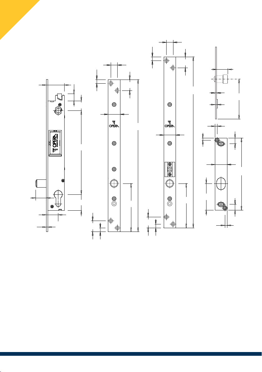
TECHNICAL SPECIFICATIONS AND DIMENSIONS - PRIMA series
23
14
25
8
8
23
320
101.5
176.5
20.5
15
33
20
3
25/30/
35/60
38/43/
48/73
UPRIGHT SECURITY SOLENOID LOCK
› Stainless steel face plate and striking plate, hardened steel deadbolt/spring latch
› Versions with fail-safe or fail-secure deadbolt/spring latch
› Power supply: 12 ÷ 24 Vdc, peak current 3 A, holding current 130 ÷ 230 mA
› Ready for interlocking between 2 or more doors
› Opto-electronic control of deadbolt / spring latch position
› Electronic control (can be disabled) of reclosing timings
› Anti-rebound alignment ball (optional)
14
25
8
23
360
96.5
23
8
25
4.5
4.5
4.5
150
12
12
55
OP57036/38 Striking plate
5
3
23
83

5
TECHNICAL SPECIFICATIONS AND DIMENSIONS - PRIMA MAXI series
30
16
9
9
26.5
26.5
440
151.5
30
4
45
57
85
325
23
10
10
440
151.5
210
30
Striking plate
6
4
23
108
UPRIGHT SECURITY SOLENOID LOCK
› Stainless steel face plate and striking plate, hardened steel deadbolt
› Versions with fail-safe or fail-secure deadbolt
› Power supply: 12 ÷ 24 Vdc, peak current 3 A, holding current 130 ÷ 230 mA
› Ready for interlocking between 2 or more doors
› Opto-electronic control of deadbolt position
› Electronic control (can be disabled) of reclosing timings
› Anti-rebound alignment ball

6
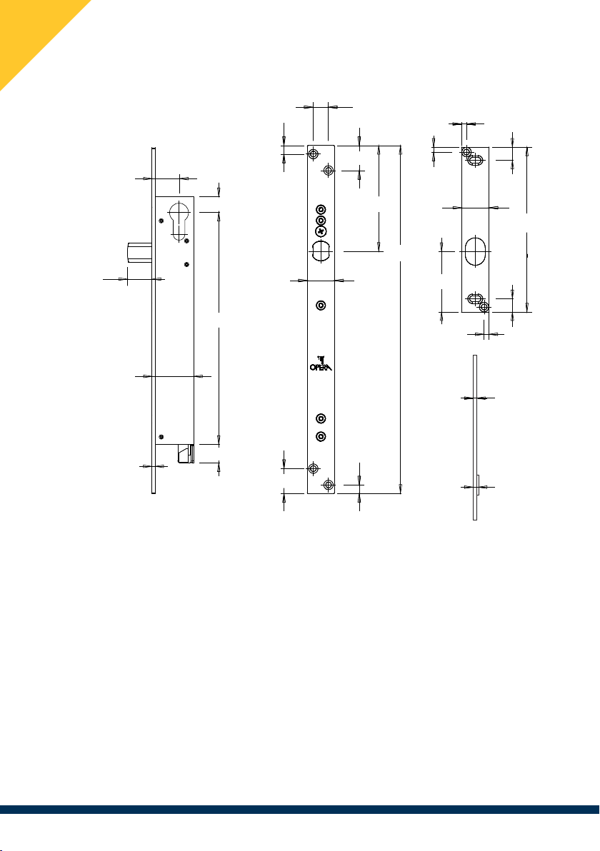
TECHNICAL SPECIFICATIONS AND DIMENSIONS - PRIMA OP series
25
4.5
4.5
4.5
150
12
12
55
215
20
3
25/30/35
35/40/45
15
15
25
23
14
8
8
23
320
97
Striking plate
5
3
UPRIGHT SECURITY SOLENOID LOCK
› Stainless steel face plate and striking plate, hardened steel deadbolt/spring latch
› Versions with fail-safe or fail-secure deadbolt/spring latch
› Power supply: 12 ÷ 24 Vdc, peak current 3 A, holding current 130 ÷ 230 mA
› Ready for interlocking between 2 or more doors
› Opto-electronic control of deadbolt / spring latch position
› Electronic control (can be disabled) of reclosing timings

7
TECHNICAL SPECIFICATIONS AND DIMENSIONS - CLASSICA series
77
28
3
210
157
90
70
20
160
76.5
10
10
25
240
115.7
23
23
8
25
OP54036/38
266/268
276/278
25
13
160
13
90
30
25
4.5
4.5
150
12
12
55
Striking plate
HORIZONTAL SECURITY SOLENOID LOCK
› Stainless steel face plate and striking plate, hardened steel deadbolt/spring latch
› Versions with fail-safe or fail-secure deadbolt/spring latch
› Power supply: 12 ÷ 24 Vdc, peak current 3 A, holding current 130 ÷ 230 mA
› Ready for interlocking between 2 or more doors
› Opto-electronic control of deadbolt / spring latch position
› Electronic control (can be disabled) of reclosing timings
› Anti-rebound alignment ball (optional)

8
8
INSTALLATION
CAUTION : do not �le or drill holes in the �xture with the solenoid bolt
installed. Do not use the solenoid bolt as a drilling template. Risk of
damage or jamming of the internal mechanics due to dust and/or shavings.
Do not weld or solder the striking plate to the door frame.
Do not use non-direct connection systems (eg. spring contacts) to pass the
connecting wires through: use a cable cover (e.g. item 08600).
20
4.5
4.5
4.5
150
12
12 55
35
45
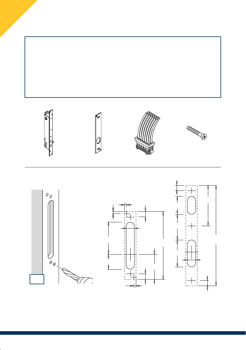
Drilling dimensions for striking plates
Supplied in package (standard)
1
(1) Drill holes for inserting the striking plate according to the diagram shown here.
The striking plate is essential for the operation of the solenoid lock.
Solenoid lock Striking plate Connector Cylinder screw
26
440
230
10
10
60
125
50
PRIMA /
PRIMA OP /
CLASSICA
PRIMA MAXI

9
9
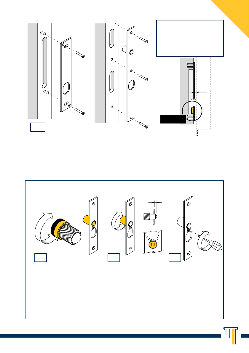
(2) Install the striking plate using appropriate screws (not supplied).
Pay attention to the orientation of the magnet: it must be installed wall side
and below the deadbolt axis, otherwise the solenoid bolt will not work.
max 6 mm
Magnet
2
ANTI-REBOUND BALL-CATCH ADJUSTMENT (SA / PRIMA MAXI version)
(1)Adjust the ball-catch strength by turning the rear ring nut while holding
the threaded portion steady until the optimum holding strength is reached.
(2) Checking that the screw on the striking plate is in the “unlocked” position,
adjust the ball-catch protrusion by turning the rear ring nut relative to the
striking plate. (3) When the adjustement is �nished, lock the thread by turning
the screw on the striking plate 90° clockwise.
Continues…
PRIMA MAXI
PRIMA / P. OP /
CLASSICA
“Unlocked” screw
If installed on ferro-
magnetic frames leave
at least 1-2 mm clearance
around the magnet.
90°
1 2 3

10
Installation on door frame: if the handle function is not necessary, the
solenoid bolt can be installed on the door frame. The use of a cable cover for
connecting wires is not required in this case.
In case the handle is required, the solenoid bolt must be mounted on
the door, using an appropriate cable cover (e.g. item 08600).
(67/87)
(67/87)
154
105
23
42
27.5
27.5
10
10
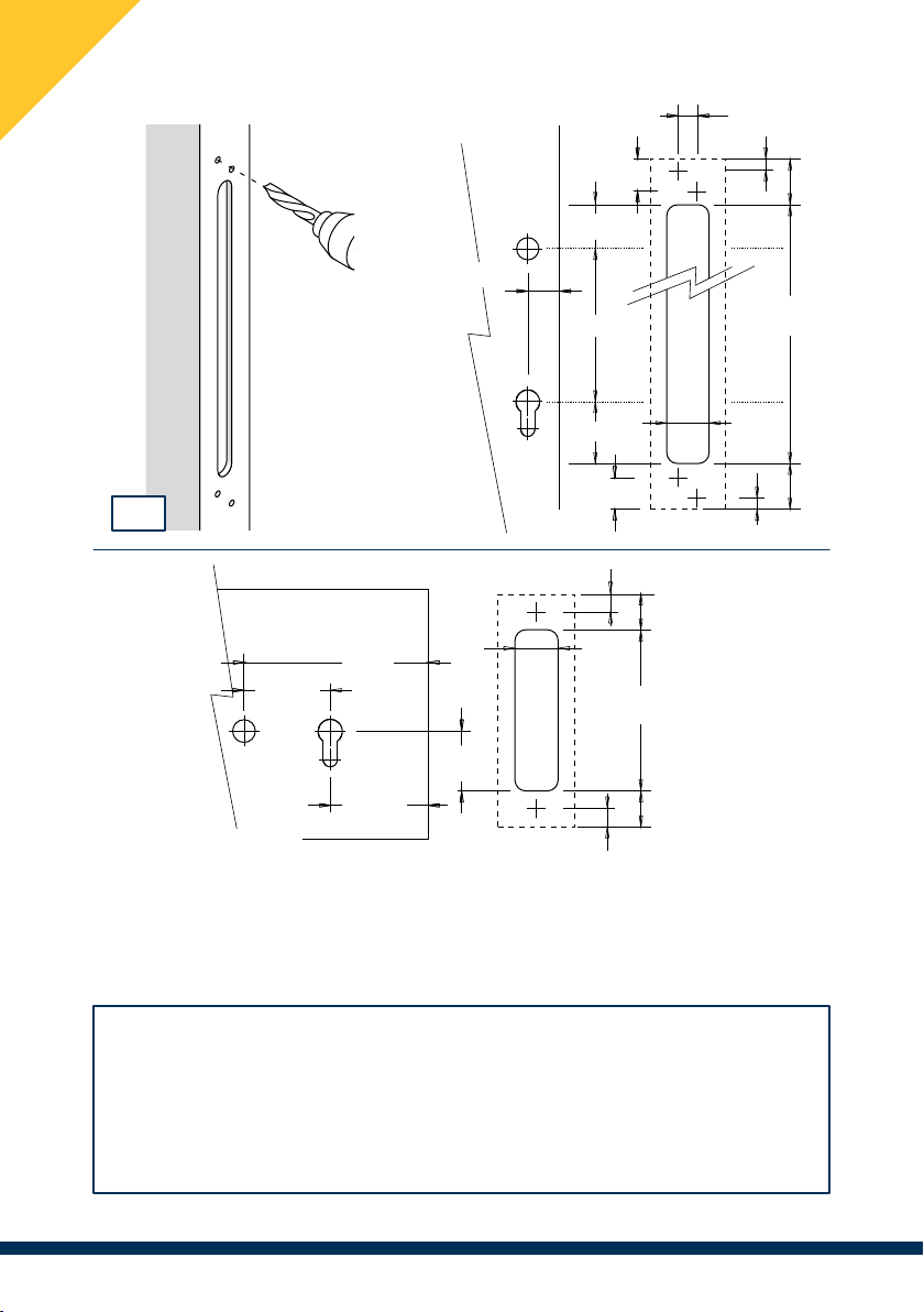
(3)Drill holes for the installation of the solenoid bolt according to the diagram
corresponding to the product to be installed.
Thoroughly clean the inside of the casing from chips and dirt.
PRIMA
CLASSICA
45.5
33
23
255
32.5
32.5
8
8
23
23
14
3
Drilling dimensions for solenoid locks
(22/27/32/60)
176.5

11
Continues…
PRIMA OP PRIMA MAXI
PRIMA / P. MAXI PRIMA OP CLASSICA
(4)Gently insert the quick plug-in connector into the receiving connector
located on the solenoid lock at the indicated position.
PAY ATTENTION TO THE DIRECTION OF INSERTION.
4
32.5
23
255
32.5
(22/27/32)
8
8
23
23
16
14
72
198
28
355
42.5
42.5
8
8
23
23
14
26 85

12
(5)Install the solenoid bolt using appropriate screws (not supplied) paying
attention to proper alignment with the hole for the cylinder.
If the solenoid lock is set up for the installation of a tamper defender, make sure it is
installed correctly.
On request, deadbolt
pointing downwards
Recommended installation
CORRECT INSTALLATION
PRIMA / P. MAXI PRIMA OP CLASSICA
5

13
SPRING LATCH REVERSIBILITY (ITEM 25900 / 25910 ONLY)
Reversibility supported only by items 25900 and 25910 with
25-30-35 mm backsets. The 60 mm backset version and the Prima OP series
shall necessairily be ordered either in the left or right hand version.
2 turns max
180°
(1)Loosen the retaining screw
(Torx M3x5) with a screwdriver.
(3)Turn the spring latch 180° and reinsert the guide pin into the hole.
(4)Close the tab, then (5)tighten the retaining screw.
(2)Pull out the tab and turn the solenoid
bolt upside down to extract the pin.
Item 25900: press lightly on the spring
latch to ease the pin out.
25900 25910
1 2
3 4 5

14
TIMING ADJUSTMENT
Perform this operation with the solenoid lock in hands (not mounted)!
Simulate the opening or closing of the door with the disassembled striking plate
magnet. To simulate the door closing, bring the striking plate close to the
solenoid lock, aligning the hole with the bolt and with the magnet facing outwards.
NOTE : timing adjustment not available on items 25910/25918
Timings are factory-set according to the Default settings (see table in facing page).
(1) Connect the electric lock to the power supply.
(2)Gently insert a small slotted screwdriver into holes T1, T2 or T3, located
on the back of the lock, pressing the button positioned inside. Hold down the
button until the LED lights up steadily (1 sec), after which the LED makes a double
flash at each timing interval. Count the number of double flashes and release
the button at the desired timing interval. The LED will flash again to con�rm the
number of seconds set.
In order to set the timing to “0” remove the screwdriver within 1 sec of the LED
lighting up. The LED will subsequently light up steadily for 1 sec.
T1
LED
T2
T3
1 2
Magnete

15
With T1 and T2 set to 0 sec : internal timings disabled, the lock can be
operated by means of external control systems by supplying or removing power.
The function of the magnetic door sensor is also disabled.
With T3 set to 0 sec : the alarm feature for prolonged opening is disabled.
To check the current timing: briefly press the concerned button.
T1 : deadbolt closure timing upon approach of the door.
T2 : deadbolt closure timing if the door is not opened.
T3 : timing of prolonged door opening alarm (only on versions
246-248-266-268).
BUTTONS
Button Range Minimum range Default setting
T1 0 to 5 sec. ±1 sec. 1 sec.
T2 0 to 60 sec. ± 5 sec. 5 sec.
T3 0 to 120 sec. ±10 sec. 10 sec.
T1
LED
T2
T3
T3
LED
T2
T1
PRIMA / PRIMA MAXI PRIMA OP CLASSICA
T3
LED
T2
T1

16
TABLE OF FUNCTIONS
Wire colour Function Description
Black Power supply
(non-polarized)
Voltage : 12 ÷ 24 Vdc
Peak current : 3 A
Current (holding) : 300 mA
Black
Orange (green band) Common contact Voltage-free microswitch for remote
signalling of deadbolt position.
See NOTES.
Red (green band) Contact (N.O.)
Brown (green band) Contact (N.C.)
Green / black Signal ground
(GND)
GND reference of each control.
Not the - of power supply.
Red / black Opening Impulsive command for deadbolt
release, from clean N.O. contact.
Brown Door status Door position signalling / alternate
magnetic sensor status. See NOTES
Yellow / black Interlock Input / output of interlock
connection.
See INTERLOCKING DIAGRAM.
Blue Alarm / Failure
(item 246 - 248
only)
Open Collector output for alarm
signalling. See NOTES.
Green RESET
(item 246 - 248
only)
N.O. impulsive contact to be
connected to GND for alarm reset.
Orange Emergency
(item 246 - 248
only)
N.O. impulsive contact to be
connected to GND for the immediate
unlocking of the door.
Yellow Lockout
(item 246 - 248
only)
N.O. contact to be steadily
connected to GND in order to disable
the opening/closing of the deadlock
(excluding Emergency).

17
Green-banded wire connections (Brown, Red and Orange) shall be used
only if local or remote signalling of deadbolt status is required (e.g. to
indicator lamp item 55010-55030).
The Alarm / Failure connection (Blue) is an open collector output that can
be connected to low-consumption loads (max 50 mA, �g. 1) or to Interface
Relays for alarm signalling (�g. 2). Connected to ground when:
• the alarm is triggered by the Emergency command . Manual reset
after minimum 10 sec via the RESET command.
• the door remains open beyond the delay set by the Prolonged
door opening feature (if the timing is not set to zero). Automatic reset
with the closing of the door or manual reset if the RESET command is triggered.
• an obstruction (failure state) is detected when the deadbolt closes.
Manual reset by triggering the RESET command.
• the opening of both interlock-connected doors is detected.
Automatic reset with the closing of either door.
• in the presence of closed deadbolt and open door. Resettable at the
end of the anomaly.
The Door status connection (Brown) can be either used for the remote
signalling of door status or to connect an alternative magnetic sensor
in place of the built-in one, eliminating the magnet installed on the striking plate
(�g. 3). Caution: do not connect to a direct relay. In order to signal
remotely the door status, use an interface circuit such as item 05259 shown in
�g. 4
NOTES
CAUTION : do not connect directly the Alarm / failure output to loads
greater than 50 mA. Risk of damage to the electronic components.

18
BLUE
BLACK
BLACK
+
LED
Buzzer
R = 1kΩ
-
Relay
BLUE
BLACK
BLACK
+
Diode
1N4007
-
Fig. 2
GREEN/
BLACK
M.S.
BROWN
+V
-V
-IN
+IN
C
N.C
N.A
BROWN
Item 05259
BLACK
BLACK
+-
Fig. 4
Fig.1: Connection of the Alarm /
Failure output directly to low-power
loads, such as LEDs or Buzzers.
Do not connect to loads
greater than 50 mA directly.
(Item 246 - 248 only).
Fig.2: Connection of the Alarm /
Failure output to an interface relay in
order to signal the alarm status by
devices with larger loads
(e.g. 230V-powered alarm devices).
(Item 246 - 248 only).
Fig.3: Connection to an alternative
magnetic sensor (M.S.)
Remove the built-in magnet,
installed on the back of the
striking plate.
Fig.4: Remote signalling of door
status using our interface circuit
item 05259.
Do not connect the brown wire
to a direct relay, risk of damage
to the magnetic sensor.
Fig. 1
Fig. 3

19
Solenoid lock Prima series
Solenoid lock Classica series
Solenoid lock Prima OP series
APPLICATION EXAMPLES
1
2
3
4
5
6
1
2
3
4
5
6
1
2
3
4
5
6
1
2
3
4
5
Legend
1Security solenoid lock
2Striking plate
3Indicator lamp
4Opening button
5Power supply
6Concealed cable cover
Installation on door frame
(read the warnings on pag. 10).

20
SAMPLE CONNECTION FOR APARTMENT BUILDING DOOR
WARNING : each conductor must be carefully insulated!
BLACK
GREEN/BLACK
BLACK
BROWN
BROWN
GREEN BAND¹
ORANGE
GREEN BAND
¹
RED
GREEN BAND
¹
RED/BLACK
YELLOW/BLACK
12/24V
3A DC
12 Vac POWER SUPPLY
INTERCOM
INTERFACE
ITEM 05258
OR RELAY 12 Vac
INDICATOR
LAMP
ITEM 55030
(OPTIONAL)
+V -V
N.O. COM
N.O. WALL MOUNTED
PUSH-BUTTON
INTERLOCK (OPTIONAL, SEE INTERLOCKING DIAGRAM)
ALTERNATIVE MAGNET CONNECTION OR
REMOTE DOOR SIGNALLING (OPTIONAL)
NL
MULTIPOLE
CONNECTOR
HOLD OPEN²
(OPTIONAL)
Please note: dotted connections are optional.
(N.C.)
(N.O.)
(COM)
CAUTION : for POWER CONNECTIONS (black wires) do not use cables
longer or with a cross-section smaller than:
For other electrical connections do not use wires with cross-section
smaller than 0,22 mm². Risk of damage and/or malfunction.
Minimum cross-section Maximum length
0,75 mm² Up to 5 m
1,5 mm² 5 to 10 m
2,5 mm² 10 to 20 m
Other manuals for PRIMA
1
This manual suits for next models
3
Table of contents
Other Opera Lock manuals
Popular Lock manuals by other brands

Kaba
Kaba LA GARD 1985 operating instructions

COMPX
COMPX Stock Locks C1801 Dimensional drawing

BURG WATCHER
BURG WATCHER TSE 3004 Assembly instruction

KTM Power Parts
KTM Power Parts 61412925020 Information

Hafele
Hafele Sola operating instructions

Gianni Industries
Gianni Industries Gk300 Series Specification sheet