OPHIR FluxGage User manual

FluxGage™
LED Luminaire Measurement System User Manual
FluxGage™
FluxGage™

FluxGage User Manual 2
1 Acronyms................................................................................................................................. 3
2 Introduction............................................................................................................................. 4
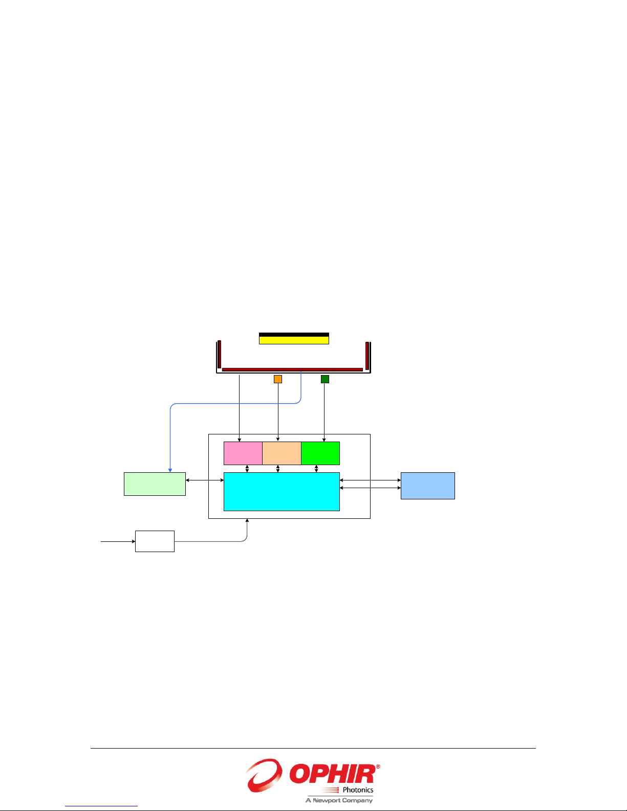
2.1 Operation principle.......................................................................................................... 4
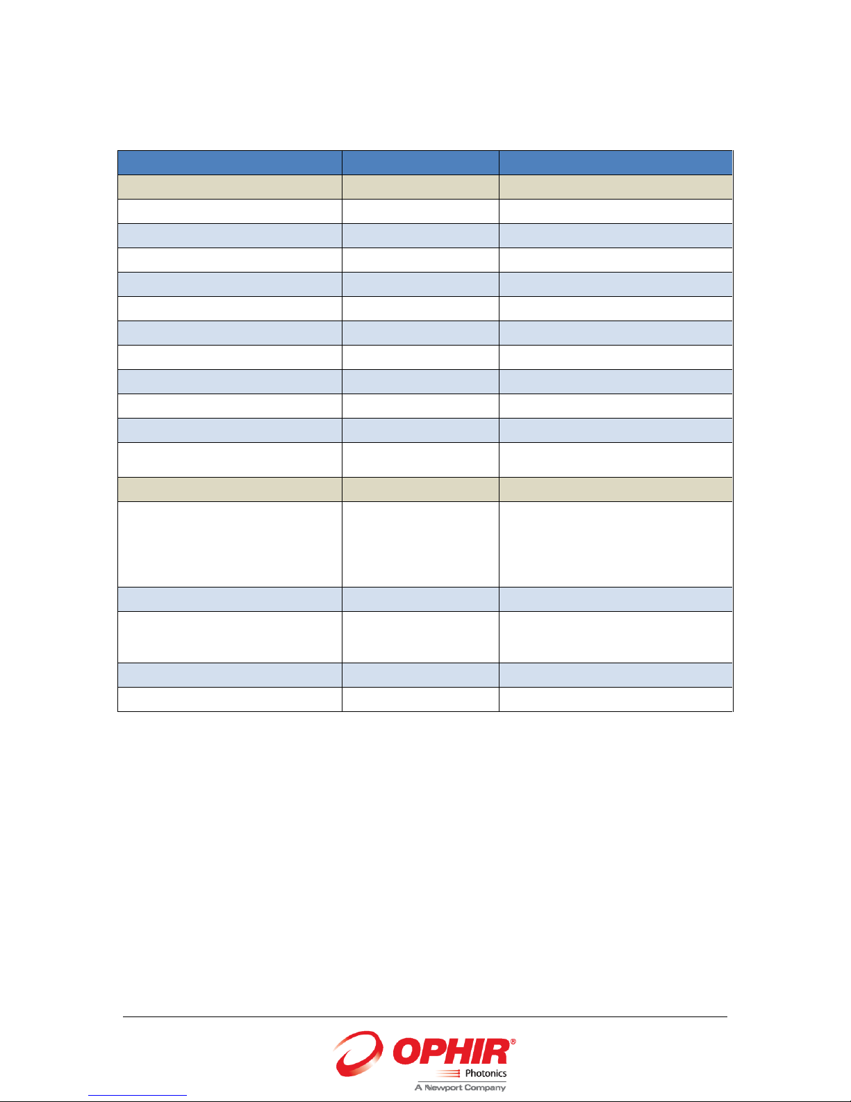
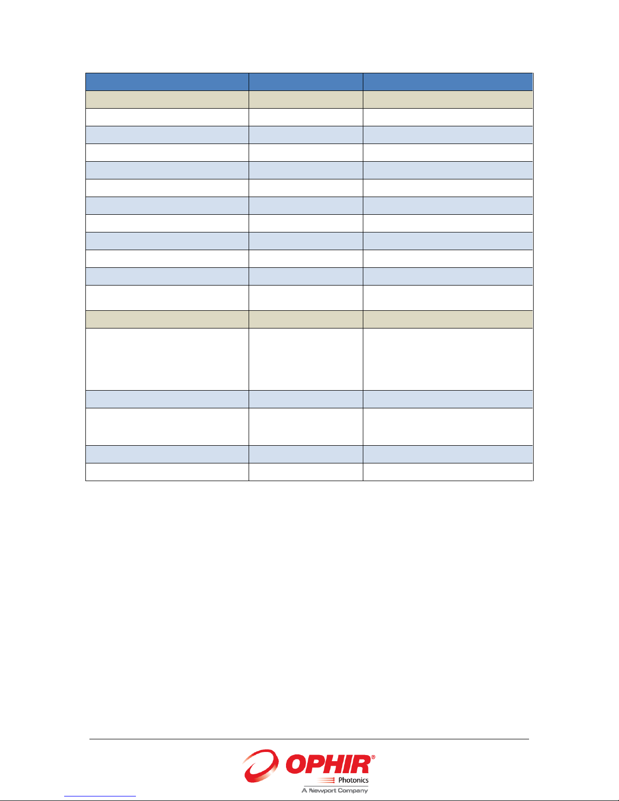
3 Specifications........................................................................................................................... 5
4 Mechanical and Electrical Installation..................................................................................... 9
4.1 Unpacking........................................................................................................................ 9
4.2 Installation..................................................................................................................... 10
5 PC and Software Installation ................................................................................................. 11
5.1 Uninstall......................................................................................................................... 15
6 Using the FluxGage................................................................................................................ 16
7 Operating the FluxGage SW .................................................................................................. 17
7.1 Top banner .................................................................................................................... 18
7.2 Control Parameters ....................................................................................................... 19
7.3 Optimization Factors ..................................................................................................... 20
7.4 Synchronized Measurement ......................................................................................... 21
7.5 Indicators....................................................................................................................... 21
7.6 Measured Parameters................................................................................................... 21
7.7 Flicker Screen................................................................................................................. 23
7.8 CRI screen ...................................................................................................................... 24
7.9 CIE 1931 Chromaticity ................................................................................................... 25
7.10 Spectrum Screen ........................................................................................................... 26
7.11 PAR screen..................................................................................................................... 27
7.12 Data logger .................................................................................................................... 28
7.13 Data save ....................................................................................................................... 30
7.14 Save to Excel.................................................................................................................. 31
7.15 Report Generator .......................................................................................................... 32
8 Calibration ............................................................................................................................. 36
8.1 Calibration of the spectrum measurement and the total flux measurement............... 36
8.2 Calibration of the total flux measurement.................................................................... 37
8.3 Calibration of the spectrometer only............................................................................ 37
8.4 Back up calibration ........................................................................................................ 38

FluxGage User Manual 3
1Acronyms
DUT –Device Under Test
CCT –Correlated Color Temperature
CRI –Color Rendering Index
PPF - Photosynthetic Photon Flux
PAR - Photosynthetically Active Radiation (PAR)
Avogadro constant –6.022*1023

FluxGage User Manual 4
2Introduction
The FluxGage LED luminaire system measures total flux, color parameters and flicker of LED
luminaires. The FluxGage measures in 2 pi geometry.
2.1 Operation principle
The FluxGage measures by collecting light using photovoltaic cells. Unlike an integrating sphere,
the FluxGage does not rely on multiple reflections and its interior is black. Light from the DUT
hits the interior walls of the FluxGage, gets absorbed and nearly no light bounces back again.
This greatly reduces the effect of the DUT’s size and shape on the measurement.
An integrated spectrometer is used to measure color parameters (CCT, CRI, Duv, and CIE 1931
chromaticity coordinate), and to translate the current produced by the photovoltaics into
lumens.
A fast photodiode sensor is used to measure flicker.
An integrated temperature sensor and fans control the temperature of the FluxGage.
Spectrometer PC
Temperature
sensor
12V
adapter
110V/220V
Solar panel
current
sensor
Flicker sensor
fast detector
circuit
Temperature
sensor circuit
photodiode
fiber
Solar cells
MCU
USB
Ethernet
12V in
Main PCB
Block Diagram

FluxGage User Manual 5
3Specifications
Parameter
Value
General
p/n 7Z02581
Outer dimensions [mm]
769x563x228
Maximal luminaire size [mm][1]
610x450
Spectral range of spectrometer [nm]
400-800
Total luminous flux range [lm]
500-40,000
Measurement time [s][2]
2
Operation Temperature [°C]
20-35
Power consumption [W]
36W
Weight [kg]
20KG
Standards
CE, ROHS
Interface
USB
Operation voltage
12v (power adapter is
supplied)
Accuracy
Repeatability
Total flux: [3]
-Absolute calibration at Ophir
-Referenced to customers’
laboratory for a particular type of
luminaire
±6%
±2%
±1%
±1%
Chromaticity accuracy [Duv][4]
±0.002
±0.0005
CCT accuracy[4]
±1.5%
±33°K at 2200°K CCT
±85°K at 5700°K CCT
±1%
CRI accuracy[4]
±1%
±0.5%
Flicker accuracy
±1%
±0.5%
[1] Refers to the area which emits light
[2] At the lowest flux
[3] For a DUT which has the same spectrum in all directions.
[4] Measured at the fiber sensor

FluxGage User Manual 6
Parameter
Value
General
p/n 7Z02582
Outer dimensions [mm]
775x564x228
Maximal luminaire size [mm][1]
610x450
Spectral range of spectrometer [nm]
400-800
Total luminous flux range [lm]
500-40,000
Measurement time [s][2]
2
Operation Temperature [°C]
20-35
Power consumption [W]
36W
Weight [kg]
20KG
Standards
CE, ROHS
Interface
USB
Operation voltage
12v (power adapter is
supplied)
Accuracy
Repeatability
Total flux: [3]
-Absolute calibration at Ophir
-Referenced to customers’
laboratory for a particular type of
luminaire
±6%
±2%
±1%
±1%
Chromaticity accuracy [Duv][4]
±0.002
±0.0005
CCT accuracy[4]
±1.5%
±33°K at 2200°K CCT
±85°K at 5700°K CCT
±1%
CRI accuracy[4]
±1%
±0.5%
Flicker accuracy
±1%
±0.5%
[1] Refers to the area which emits light
[2] At the lowest flux
[3] For a DUT which has the same spectrum in all directions.
[4] Measured at the fiber sensor

FluxGage User Manual 7
Parameter
Value
General
p/n 7Z02584
Outer dimensions [mm]
775x564x228
Maximal luminaire size [mm][1]
610x450
Spectral range of spectrometer [nm]
400-800
Total luminous flux range [lm]
100-20,000
Measurement time [s][2]
2
Operation Temperature [°C]
20-35
Power consumption [W]
36W
Weight [kg]
20KG
Standards
CE, ROHS
Interface
USB
Operation voltage
12v (power adapter is
supplied)
Accuracy
Repeatability
Total flux: [3]
-Absolute calibration at Ophir
-Referenced to customers’
laboratory for a particular type of
luminaire
±6%
±2%
±1%
±1%
Chromaticity accuracy [Duv][4]
±0.002
±0.0005
CCT accuracy[4]
±1.5%
±33°K at 2200°K CCT
±85°K at 5700°K CCT
±1%
CRI accuracy[4]
±1%
±0.5%
Flicker accuracy
±1%
±0.5%
[1] Refers to the area which emits light
[2] At the lowest flux
[3] For a DUT which has the same spectrum in all directions.
[4] Measured at the fiber sensor

FluxGage User Manual 8
Parameter
Value
General
p/n 7Z02585
Outer dimensions [mm]
769x564x228
Maximal luminaire size [mm][1]
610x450
Spectral range of spectrometer [nm]
400-800
Total luminous flux range [lm]
100-20,000
Measurement time [s][2]
2
Operation Temperature [°C]
20-35
Power consumption [W]
36W
Weight [kg]
20KG
Standards
CE, ROHS
Interface
USB
Operation voltage
12v (power adapter is
supplied)
Accuracy
Repeatability
Total flux: [3]
-Absolute calibration at Ophir
-Referenced to customers’
laboratory for a particular type of
luminaire
±6%
±2%
±1%
±1%
Chromaticity accuracy [Duv][4]
±0.002
±0.0005
CCT accuracy[4]
±1.5%
±33°K at 2200°K CCT
±85°K at 5700°K CCT
±1%
CRI accuracy[4]
±1%
±0.5%
Flicker accuracy
±1%
±0.5%
[1] Refers to the area which emits light
[2] At the lowest flux
[3] For a DUT which has the same spectrum in all directions.
[4] Measured at the fiber sensor

FluxGage User Manual 9
4Mechanical and Electrical Installation
4.1 Unpacking
Place the FluxGage box on a flat surface.
Open the box and remove the top piece of foam.
Remove two side pieces of foam.
Reach into the clearance left by the two pieces and lift the FluxGage from the box.

FluxGage User Manual 10
4.2 Installation
The FluxGage can be operated facing up or down.
Allow 200mm (8’’) clearance for the fans.
Connect the power supply to the mains and to the DC input. The power plug is secured
by turning it half turn clockwise.
Connect the PC to the USB port.
The inner surfaces can be cleaned with a damp cloth or clean compressed air. Solvents
should not be used.
Warning. The FluxGage is a heavy object which can cause injury or death if falls on a
person. Take proper precautions.

FluxGage User Manual 11
5PC and Software Installation
Select 32bit or 64bit according to the operating system.
Install:
Double click on setup.exe
Install start :

FluxGage User Manual 12
Click on [Next >>]

FluxGage User Manual 13
Click on [Next >>]

FluxGage User Manual 14
Install in progress

FluxGage User Manual 15
Click on [Finish]
5.1 Uninstall
To uninstall go to: Control Panel > Programs > Programs and Features. Select FluxGage and
[Uninstall]

FluxGage User Manual 16
6Using the FluxGage
The DUT should be placed over the opening of the FluxGage and centered. The DUT can be
supported by an adapter plate secured to top surface of the FluxGage using the ¼-20 threads.
The adapter plate should have an opening cut out to allow light from the DUT to reach the
FluxGage.
Taking measurements with FluxGage:
Step 1. AutoSet
Place the DUT over the FluxGage and turn it on. Press Autoset. The FluxGage will automatically
set the integration time of the spectrometer and other internal settings.
Step 2. Background
Turn the DUT off. Press ‘Background’. The FluxGage will measure the background signal of the
spectrometer and the solar panel current meter. These will be subtracted from the actual
measurement. Do not move the DUT after the background measurement. The FluxGage will
start measuring immediately after the background measurement is done.
Step 3. Measurement
Turn the DUT on. The FluxGage will now measure and display correct results.

FluxGage User Manual 17
7Operating the FluxGage SW

FluxGage User Manual 18
7.1 Top banner
FluxGage
Save –Save the current measurement to a tab delimited text file
Save to excel –add the current measurement to an excel file
Report –Generate a PDF report
Exit - Exit the SW
Mode
Flicker –Detailed flicker screen
CRI –Detailed CRI (Color Rendering Index) screen
CIE1931 –Chromaticity coordinates
Spectrum –View and save spectrum in [W/nm]
PAR –Detailed PAR (Photosynthetically Active Radiation) screen
Logging –Data logging screen
Calibration
Open the calibration screen.
Help
Click on About to see information on the hardware and software versions.

FluxGage User Manual 19
7.2 Control Parameters
7.2.1 Autoset
‘Autoset’ sets the optimal spectrometer integration time and other internal settings by
measuring the incoming light from a DUT.
7.2.2 Background
‘Background’ should be done after Autoset with the DUT in place and turned off. The FluxGage
stores the background value of the spectrometer and later subtracts it from the actual
measurement.
7.2.3 Averages
Adding averaging will improve the stability of the measurement. If the integration time
multiplied by the number of averages exceeds 500ms, the photovoltaics and photodiode will
also increase their measurement time and improve their stability.
7.2.4 Abort
The abort button resets the current measurement and starts a new one. This is useful if the
current measurement take a long time, for example due to many averages.
7.2.5 More settings
The ‘more setting’ button extends the SW window to reveal more options described in the next
section.

FluxGage User Manual 20
7.3 Optimization Factors
Optimization factors can improve the accuracy of the total flux measurement. The performance
of the FluxGage system was optically modeled for various luminaire sizes and illumination beam
angles, and optimization factors adjust the total flux measurement accordingly.
Luminaire Length
Enter the luminaire length in [cm]
Luminaire Width
Enter the luminaire width in [cm]
Table of contents