STL EXTRA-N-LED User manual

EXTRA-N-LED, MULTIEXTRA-N-LED, EXTRA-N-LED-Em
Installation and Operations Manual
The explosion proof light tting meet the standards according to the UK SI 2016 No.1107 (incl.
amendments). They can be used in areas with danger of explosion as follows:
Area with danger of explosive Marking
of exterior
ambient
Classication of area
Marking Complusory regulation
Danger of explosion of
inammable dust
BE3N1 ZONE 22 ČSN EN 60079-14
ČSN EN 60079-10-2
Danger of explosion of
inammable gas and vapors
BE3N2 ZONE 2 ČSN EN 60079-14
ČSN EN 60079-10-1
phX 2 UKEX 1202X
BII 3G Ex nR IIC T6 Gc
BII 3D Ex tc IIIC T80°C Dc
IP66, insulation class I
Operation and maintenance instructions:
The light ttings, which operate in areas of above mentioned premises, are under the requirements resulting from compulsory regulations of valid EN:
- The light tting must not be open, if the terminal block is alive.
- Free outlets for supply cable must be sealed with plugs M20.
- Any change or replacements of components of the light ttings, which can inuence the protection before the danger of explosion, are forbidden.
- The repair of the light ttings can be done only by person with relevant qualication, only with original spare parts and in compliance with the latest regulations.
1) Certicate of type phX 22 UKEX 1202X
Page 1/3
Type A(mm) B (mm) C (mm)
EXTRA-N-LED-218 670 155 105
EXTRA-N-LED-236 1280 155 105
EXTRA-N-LED-258 1580 155 105
Lighting xtue dimensions:
In case of any erving on light tting in premises with danger of exlosion, the national safety rules
and regulation for prevention of accidents are to be observed.
EXTRA-N-LED are LED dust proof and waterproof lighting xtures designed for lighting premises
with danger of explosions.
EXTRA-N-LED-Em - non maintained emergency lifting.
MULTIEXTRA-N-LED - maintained emergency lifting.
Pic.1
With fastening spring directly on the base
(included)
Pic. 2
With steel wire hanger
(not included)
Pic. 3
With a cable suspension
(not included)
Maximum number of continuously connected luminaires for circuitbreaker type B10A
EXTRA-N-LED
MULTIEXTRA-N-LED
EXTRA-N-LED-2500-218 23
EXTRA-N-LED-5000-218 23
EXTRA-N-LED-5000-236 23
EXTRA-N-LED-10000-236 18
EXTRA-N-LED-7500-258 18
EXTRA-N-LED-12550-258 18
EXTRA-N-LED-16700-258
EXTRA-N-LED-20000-258 9
Technical data:
Permited range of operating temperatures for 220-240V, 50/60Hz
EXTRA-N-LED-2500/5000-218/236 -20°C to +60°C
EXTRA-N-LED-5000/7500-218/258 -20°C to +55°C
EXTRA-N-LED-12550-258 -20°C to +45°C
EXTRA-N-LED-10000-236 -20°C to +40°C
EXTRA-N-LED-16700/20000-258 -20°C to +40°C
MULTIEXTRA-N-LED-2500-218 0°C to +35°C
MULTIEXTRA-N-LED-5000/7500-236/258 0°C to +40°C
MULTIEXTRA-N-LED-12550/258 0°C to +35°C
EXTRA-N-LED-Em-500-218/236/258 0°C to +50°C
EXTRA-N-LED-Em-1000-218/236/258 0°C to +40°C
Nominal voltage and frequency:
for electronic ballast HELVAR: 220-240V, 0/50-60Hz
for electronic ballast TRIDONIC: 220-240V, 0/50/60Hz
for electronic ballast TCI: 220-240V, 0/50-60Hz
for emergency unit AWEX: 220-240V, 50/60Hz
for emergency unit TRIDONIC: 220-240V, 50/60Hz

L TN
Mountig:
1. Remove reector from the luminaire.
2. Remove the bag with equipment.
3. The side opening in the body plant the cable gland (which is included in the luminaire equipment), and on the other side of her body screw the nut.Cable gland nut to the body, tighten torque 2,7Nm.
4. To the hinges on the body insert clips from equipment luminaire.
5. Fasten the lighting xture on the base: a) With fastening spring directly on the base pic. 1
b) With steel wire hanger (no included) pic. 2
c) With a cable suspension (no included) pic. 3.
Note: another method of fastening is not allowed!
6. Pull the power cable through the cable gland. Tighten bushings to a state of partial deformation of the rubber sealing washers, tightening torque 2,5Nm.Supply cable must have an outer diameter
in the range (see. Table sealing areas), which is a necessary condition for correct function of cable gland. Hole for power cable in the housing, which is not used cable gland (which is contained in the
equipment luminaires), seal blanking plug. In the luminaire is not allowed to use respiratory protective plugs and cable glands breathing
7.Connect the suppling cable to the free part of incoming terminal strip as follows:
EXTRA-N-LED EXTRA-N-LED-Em MULTIEXTRA-N-LED
Lphase
conductor
L1 cond. of charging
phase
L1 cond. of charging
phase
- - - - L2 cond. of switching
phase
Nneutral
conductor
Nneutral
conductor
Nneutral
conductor
Tprotective
conductor Tprotective
conductor Tprotective
conductor
* To each pole of terminal block can be connected two conductors in cut 0, 75 - 2, 5 mm2. In case of through-wiring connection it is necessary to use accessories for such connection!
In case that the label with the description of connection is glued on the reector of luminaire, you must do connection according this description.
8. Fasten reector back to plastic handles.
9. Insert the stainless clips (which are included in the equipment) into the prepared plugs on body.
10. Attach the glass cover on the xture:
- attach the optical cover that all round landed on a seal which is disposed in the xture
- Optical cover secure by the stainless steel clips, secure each clip with the screw included with the luminaire.
Table: List of cable glands:
Cable glands Diameter of the cable for cable glands
M25x1,5
OBO V-TEC Ex ∅ 7 mm - 12 mm
CEAG CHG 960 92.. P… ∅ 5,5 mm - 13 mm
WISKA ESKE/1 (S)(-L)(-*)(-RDE) ∅ 7 mm - 13 mm
ELFIT UNI ∅ 7 mm - 12 mm
BIMED LYRA (EURO-TOP) ∅ 7 mm - 12 mm
Page 2/3
Test of operation:
For correct operation it is necessary to observe enclosed instruction about testing of emergency xtures. Switch the luminaire o the mains voltage. The emergency LED module must light.
The green LED in the reector is o. Should the emergency lamp be extinguished within the test period though the battery is fully charged, the latter will have to be replaced by a new battery set.
Warning: The full battery capacity will be available after approximately three charging/discharging cycles.
Battery change:
"Replace the battery in a non-explosive environment"
Battery change is necessary when the xture doesn´t observe the conditions of rated operation period durability. In explosive area it is prohibited to disconnect battery for emergency unit. It is allowed to
disconnect the xture from supply voltage and take remove reector from the xture.
11. Disconnect the xture from supply voltage.
12. Remove reector from the housing.
13. Disconnect cable from terminal block.
14. Disconnect battery from emergency unit in non-explosive area as follows „-“black conductor and „+“red conductor.
15. Unbolt the nut of battery holder
16. Remove the old battery.
17. Screw the new battery (mark the date of operation start).
18. Connect conductors to battery as follows „+“red conductor and „-“black conductor.
19. Connect the xture to supply voltage.
20. Equip with reector and cover. Fix it with the clips.
WARNING: The battery in the xture can be changed for the same type or the same parameters only!!!

s
In case of any interventions on xture lighting in premises with danger of explosion, the national safety rules and regulation for prevention od accidents are to be observed.
EXTRA-N-LED are LED based dust proof and waterproof lighting xtures designed for lighting premises with danger of explosions.
The light source and gasket in this lighting xture can be replaced only the manufacturer, its contractual service personnel or a similarly qualied person. When installing
lighting xtures, observe the ESD safety using appropriate tools!
When the mounting instructions are not observed, the producer can´t be responsible for incidental damages incurred.
The light source and gasket in this lighting xture can be replaced only producer, its contractual service personnel or a similarly qualied person. Any modication or
replacement of components on the luminaire that aects the protection against dangerous explosions is prohibited.
Repairs to luminaires may only be carried out by a suitably qualied person and only with original spare parts.
ATTENTION!!!
For wall installation of lighting xture must be LED driver positoned facing downwards
WARNING – potential danger of electrostatic charging.
WARNING – the lighting xture must be installed in the position, which does not allow the touch of persons and parts of the xture. WARNING – the lighting
for xed installation.
WARNING – the xture should be cleaned with damp duster only. It is necessary to keep periodic cleaning intervals of lighting xture WARNING – do not open
under voltage.
WARNING – replace protective cover
Page 3/3
MWS -Optional Microwave Sensor
Factory settings:
- Detection range: 100%
- Hold Time: 5s
- Daylight Threshold: Disabled

Declaration of Conformity
_________________________________________________________________________________________
Product: LED Linear luminaire EXTRA-N-LED, EXTRA-N-LED-Em, MULTIEXTRA-N-LED
Models: LED PCB –3W-120W
EXTRA-N-LED-1250-218 -20°C < ta <+45°C
EXTRA-N-LED-2500-218 -20°C < ta <+60°C
EXTRA-N-LED-5000-218 -20°C < ta <+55°C
EXTRA-N-LED-2500/5000-236 -20°C < ta <+60°C
EXTRA-N-LED-10000-236 -20°C < ta <+40°C
EXTRA-N-LED-3750/7500-258 -20°C < ta <+55°C
EXTRA-N-LED-12550-258 -20°C < ta <+45°C
EXTRA-N-LED-16700/20000-258 -20°C < ta <+40°C
MULTIEXTRA-N-LED-1250/2500-218 0°C < ta <+35°C
MULTIEXTRA-N-LED-2500/5000-236 0°C < ta <+40°C
MULTIEXTRA-N-LED-3750/7500-258 0°C < ta <+40°C
MULTIEXTRA-N-LED-12550-258 0°C < ta <+35°C
EXTRA-N-LED-Em-500-218/236/258 0°C < ta <+50°C
EXTRA-N-LED-Em-1000-218/236/258 0°C < ta <+40°C
EXTRA-N-LED-H-12550-258 -20°C < ta <+45°C
EXTRA-N-LED-H-16700/20000-258 -20°C < ta <+40°C
IP66, Class I,
phX 22 UKEX 1202X
II 3G Ex nR IIC T6 Gc
II 3D Ex tc IIIC T80°C Dc
Manufacturer: STL INTERNATIONAL LTD
Hill Farm, Linton Hill, Maidstone, Kent, ME17 4AL, United Kingdom
We declare, under our sole responsibility, that the object of the declaration described above is in conformity with
the relevant UK Statutory Instruments (and their amendments):
2016 No.1107 The Equipment and Protective Systems Intended for Use in Potentially
Explosive Atmospheres Regulations 2016
2016 No.1091 The Electromagnetic Compatibility Regulations 2016
2012 No.3032 The Restriction of the Use of Certain Hazardous Substances in Electrical
and Electronic Equipment Regulations 2012
The following standards have been applied for certification:
EN 60079-0:2018 including amendments
EN 60079-15:2019
EN 60079-31:2014
EN 60598-1:2015 including amendments
EN 60598-2-1:1989 including amendments
EN 60598-2-22:2014 including amendments
EN 60598-2-24:2013
EN 62471:2008
EN 55015:2019 including amendments
EN 61000-3-2:2019 including amendments
EN 61547:2009
Maidstone, 5 December 2022
Ing Peter Heyse
Place and date of issue
Managing Director
SCAN QR FOR STL WEBSITE
This manual suits for next models
14
Popular Lantern manuals by other brands
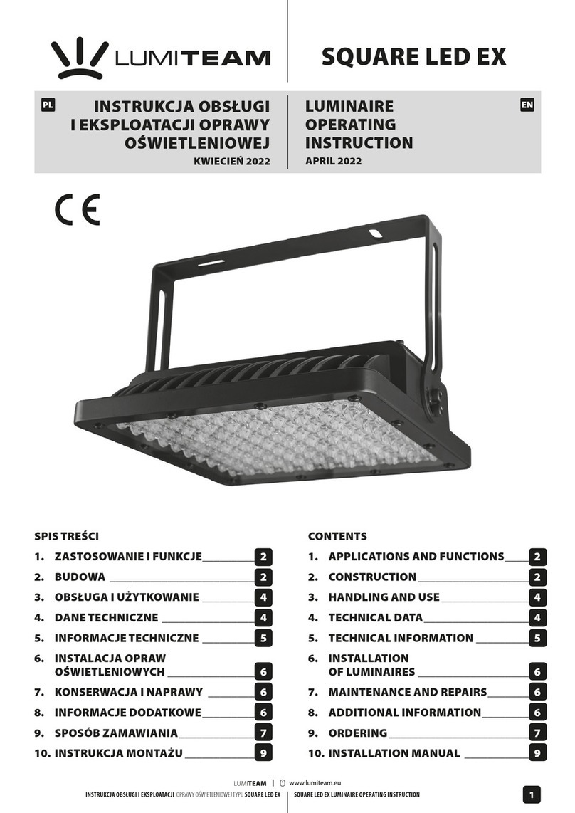
LUMI TEAM
LUMI TEAM SQUARE LED EX Operating instruction
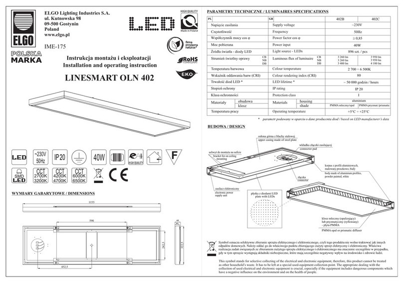
Elgo
Elgo LINESMART OLN 402 Installation and operating instruction
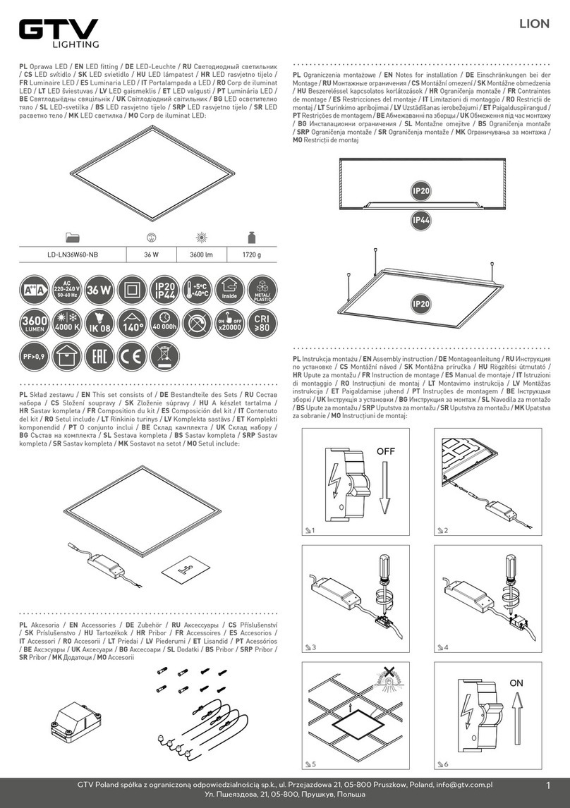
GTV
GTV LD-LN36W60-NB manual

Ilti Luce
Ilti Luce BLUX08034250AA Mounting instructions
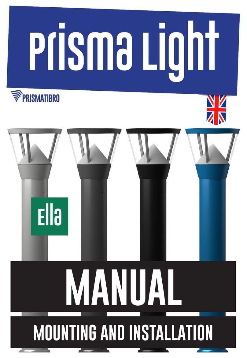
Prismatibro
Prismatibro Prisma Light Ella manual

Ilti Luce
Ilti Luce BLUX08016250AA Mounting instructions


