manuals.online logo
Brands
  1. Home
  2. •
  3. Brands
  4. •
  5. Leviton
  6. •
  7. Accessories
  8. •
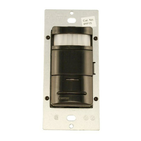
  9. Leviton Decora ODS10-IQ User manual

Leviton Decora ODS10-IQ User manual

WARNINGS AND CAUTIONS:
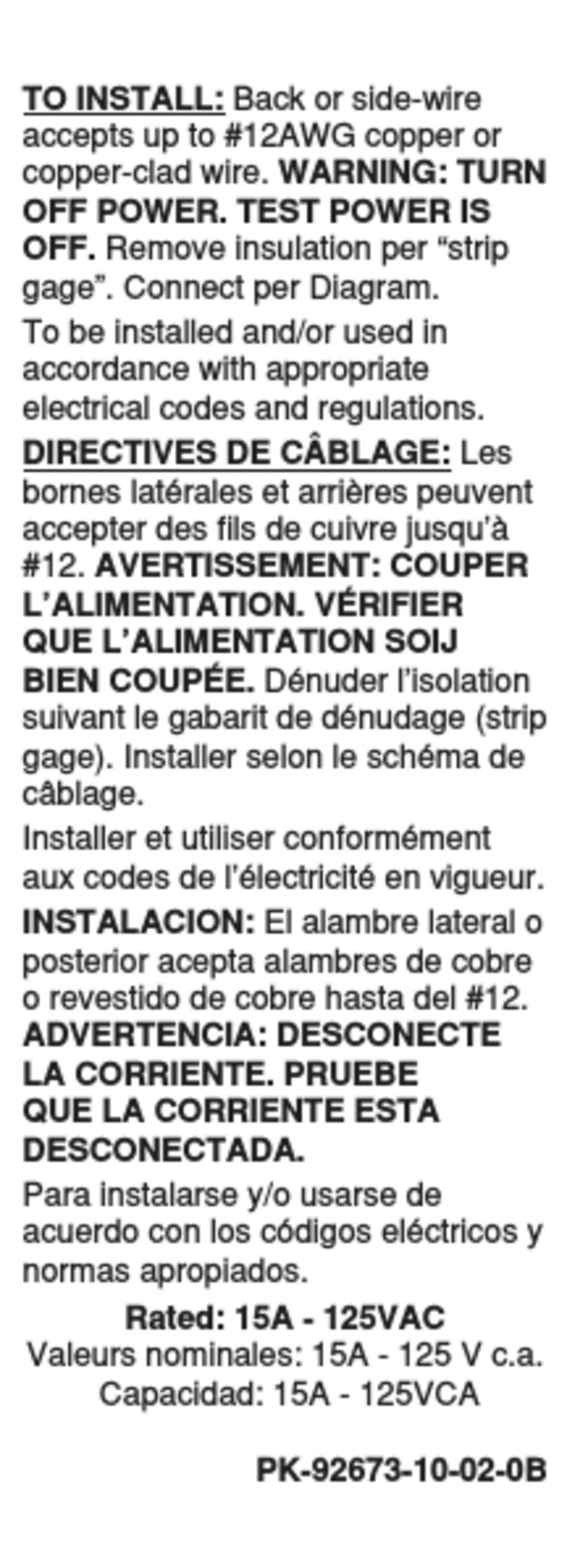
• TO AVOID FIRE, SHOCK, OR DEATH;TURN OFF POWER AT CIRCUIT BREAKER OR FUSE AND TEST THAT THE POWER IS OFF BEFORE WIRING!
• DO NOTcontrolaloadinexcessofthespeciedratings.Damagetotheunit,re,electricshock,personalinjuryordeathcanoccur.
Checkyourloadratingstodeterminesuitabilityforyourapplication.
• Tobeinstalledand/orusedinaccordancewithelectricalcodesandregulations.
• Ifyouarenotsureaboutanypartoftheseinstructions,consultanelectrician.
WARNINGS AND CAUTIONS:
• Donotinstallthisunittocontrolareceptacle.
• Donottouchthesurfaceofthelens.Cleanoutersurfacewithadampclothonly.
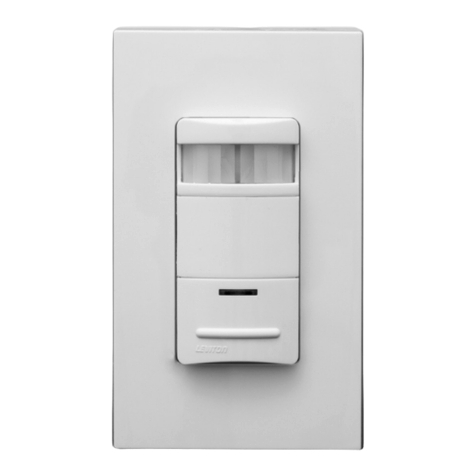
• TheCat.No.ODS10-IQoccupancysensorisintendedtoreplaceastandardlightswitch.
• UsethisdeviceONLY WITH COPPER OR COPPER CLAD WIRE.
SinglePole(OneLocation)orMulti-Location
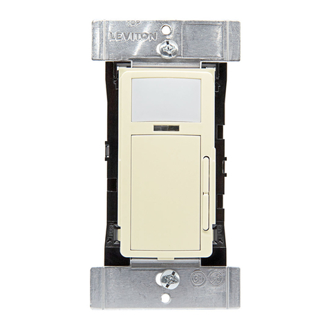
Designer Wall Switch Occupancy Sensor
Cat. No. ODS10-IQ
Incandescent - 800W-6.67A@120V-Fluorescent -1200VA-10A@120V-Fluorescent -2700VA-10A@277V-Supplemental - 1/4hp-5.8A@120V
No Minimum Load Required
Compatiblewithelectronicandmagneticballasts,electronicandmagneticlow-voltageballasts,incandescentlamps,andfans.
INSTALLATION INSTRUCTIONS
TOOLS NEEDED TO INSTALL YOUR SENSOR
Slotted/PhillipsScrewdriver ElectricalTape Pliers
Cutters   SmallSlottedScrewdriver
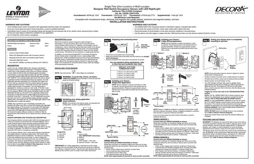
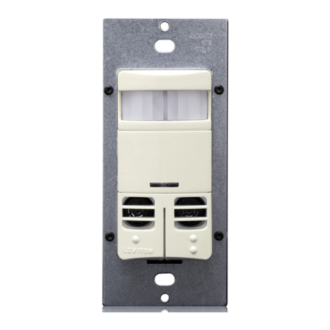
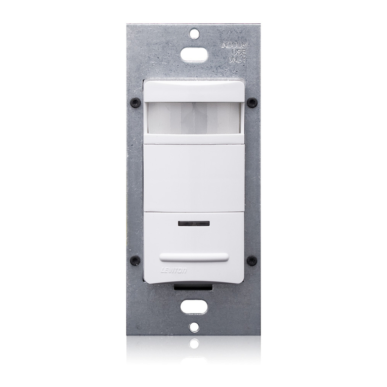
LevitonCat.No.ODS10-IQ,DesignerWallSwitchOccupancySensor,
isdesignedtodetectmotionfromaheat-emittingsource(suchas
apersonenteringaroom)withinitseld-of-view(monitoredspace)
andautomaticallyswitchlightsONandOFF.Thecontrolledlightswill
remainONuntilnomotionisdetectedandthescheduledtime-delay
hasexpired.
Cat. No. ODS10-IQ is UL and cUL listed.
TheOccupancySensorsensesmotionwithinitscoverageareaof
2100sq.ft(195.1m2)maximumandcontrolstheconnectedlighting.
Thisisaself-containeddevicewhichprovidessensingandlight
control.TheOccupancySensorwillturnthelightsONwhenmotion
isinitiallydetected,andkeepthelightsONforaslongasmotionis
detected.
TheOccupancySensorusesasmallsemiconductorheatdetectorthat
residesbehindamulti-zoneopticallens.ThisFresnellensestablishes
dozensofzonesofdetection.Thesensorissensitivetotheheat
emittedbythehumanbody.Inordertotriggerthesensor,thesource
ofheatmustmovefromonezoneofdetectiontoanother.Thedevice
ismosteffectiveinsensingmotionacrossitseld-of-view,andless
effectivesensingmotiontowardsorawayfromitseld-of-view(refer
to Field-of-View diagrams).Keepthisinmindwhenselectingthe
installationlocation(refer to Field-of-View diagrams).
Notethatoccupancysensorsrespondtorapidchangesin
temperature,socareshouldbetakennottomountthedevice
nearaclimatecontrolsource(i.e.radiators,airexchanges,andair
conditioners).Hotorcolddraftswilllooklikebodymotiontothedevice
andwilltriggeritiftheunitismountedtooclose.It is recommended
to mount the Occupancy Sensor at least 6 ft. away from then
climate control source.Thedevicecanbemountedinasinglegang
wallbox.
Inaddition,itisalsorecommendedNOTtomounttheOccupancy
Sensordirectlyunderalargelightsource.Largewattagebulbs
(greaterthan100Wincandescent)giveoffalotofheatandswitching
thebulbcausesatemperaturechangethatcanbedetectedbythe
device.MounttheOccupancySensoratleast6ft.awayfromlarge
bulbs.Ifitnecessarytomountthedevicecloser,lowerthewattageof
thebulbdirectlyoverhead.
WARNING:TO AVOID FIRE, SHOCK, OR DEATH; TURN
OFF POWER atcircuitbreakerorfuseandtestthatpoweris
offbeforewiring!
Step 1
ONOFF
ONOFF
ONOFF
ONOFF
ONOFF
ONOFF
ONOFFONOFF
ONOFF
ONOFF
ONOFF
ONOFF
• Pulloffpre-cutinsulationfromsensorleads.
• Makesurethattheendsofthewiresfromthewallboxarestraight
(cut if necessary).
• Removeinsulationfromeachwireinthewallboxasshown.
Preparing and connecting wires:
9/16"
(1.4 cm)
Strip Gage
(measure bare
wire here)
Cut
(if necessary)
Step 3
INSTALLING YOUR SENSOR
NOTE:UsecheckboxeswhenStepsarecompleted.
Installing your Sensor – Single-Pole Application:
Step 4
Identifying your wiring application
(most common):
Step 2
WIRING SENSOR:
Connect wires per WIRING DIAGRAM as follows:Screwwireconnector
onclockwisemakingsuretherearenobareconductorsbelowthewire
connectors.Secureeachconnectorwithelectricaltape.
• GreenorbarecopperwireinwallboxtoGreenlead.
• LineHotwallboxwiretoBlacklead.
• LoadwallboxwiretoBluelead.
NOTE: Allow 1 minute for warm-up after connecting and energizing.
WIRING SENSOR 1:
Connect wires per WIRING DIAGRAM as follows:
• GreenorbarecopperwireinwallboxtoSensor1Greenlead.
• LineHot(common)wallboxwireidentied(tagged)whenremovingold
switchandFirsttravelerfromSensor2toSensor1Blacklead.
• SecondTravelerwallboxwirefromSensor2toSensor1Bluelead.
WIRING SENSOR 2:
Connect wires per WIRING DIAGRAM as follows:
• GreenorbarecopperwireinwallboxtoSensor2Greenlead.
• Loadwallboxwireidentied(tagged)whenremovingoldswitchand
SecondTravelerfromSensor1toSensor2Bluelead.
• FirstTravelerLineHotfromSensor1toSensor2Blacklead.
NOTE: Allow 1 minute for warm-up after connecting and energizing.
NOTE: TheCat.No.ODS10-IQrequiresagroundwiretooperate
properly.Ifthereisnogroundwire,ensureelectricalboxisgroundedand
attachgroundwiretoboxwithascrew.Ifthegroundwireisoatingthis
devicewillnotwork.
NOTE: TheCat.No.ODS10-IQrequiresagroundwiretooperate
properly.Ifthereisnogroundwire,ensureelectricalboxisgroundedand
attachgroundwiretoboxwithascrew.Ifthegroundwireisoatingthis
devicewillnotwork.
NOTE:EithersensorcanturnthelightsON.Bothsensorsmusttimeout
toOFF.
DESCRIPTION
DI-02X-ODS10-00A
• AutoON/AutoOFF
• Leviton’sDecora®styledesign
• Switcheselectronicballasts
• LowProle,tamper-resistantlens
• AmbientLightOverride
FEATURES
3-Way
1. LineorLoad(Seeimportant*instruction)
2. Ground
3. FirstTraveler–notecolor
4. SecondTraveler–notecolor
Single-Pole
1.Line(Hot)
2.Ground
3.Load
IMPORTANT:For3-Wayapplications,notethatoneofthescrew
terminalsfromtheoldswitchbeingremovedwillusuallybeadifferent
color(Black)orlabeledCommon.Tagthatwirewithelectricaltapeand
identifyasthecommon(LineorLoad)inbothswitchwallboxes.
Step 5 Installing your Sensor – 3-Way Wiring Application:
NOTE:Dresswireswithabendtorelievestresswhenmounting
device.
•
 Positionallwirestoprovideroominoutletwallboxfordevice.
• Partiallysecuredeviceusinglongmountingscrewsprovided.
• Restorepoweratcircuitbreakerorfuse.
NOTE:ToavoidPERMANENTDAMAGEtotheunit,becareful
NOTTOOVERTURNthecontrolknobsorleverswhensettingthe
Sensor.Thecontrolscanbeaccessedbyremovingthewallplate
(ifapplicable)andcontrolpanelcover(refer to Control Panel
Diagram).Useasmallstraightbladescrewdrivertoadjustknobs
andandangertoadjusttheblinderlevers.
NOTE: DO NOT pressinonblinderleversoruseexcessiveforce
(refer to Control Panel Diagram).
• AttachtheControlPanelcoverwhenthedesiredsettingsare
complete.
If lights do not turn ON, refer to the TROUBLESHOOTING section.
Testing your Sensor prior to completely
mounting in wall box:
Step 6
Device Mounting:
TURN OFF POWER AT CIRCUIT
BREAKER OR FUSE.
Step 7
Restore Power:
Restorepoweratcircuitbreakerorfuse.
Installation is complete.
LeavetheroomandthelightswillturnOFFafterthe
selectedtime-outexpires.
Step 8
Installationmaynowbecompletedbytightening
mountingscrewsintowallbox.Attachwallplate.
Hot (Black)
Neutral (White)
Load
Sensor
Black
Black
White
Blue
Green
Ground
Line
120-277VAC
50/60 Hz
Hot
(Black)
Neutral (White)
Load
Blue Blue
Black
Green
Ground
Black
White
Black
Line
120-277VAC
50/60 Hz Green
Ground
Sensor 2
Sensor 1
2
1
34
1
3
2
AutoON/AutoOFF:ThisdeviceisfactorysettooperateinAutoON/Auto
OFFmode.Thepushbuttonhasbeendisabledtopreventtheuserfrom
manuallycontrollingthelights.InAutoON/AutoOFFmodethelightswill
automaticallyturnONwhenmotionisdetected.Intheabsenceofmotion,
afterthetimeoutexpires,thelightswillturnOFF.
SETTINGS
OPERATION
• Fortechnicalassistancecontactusat1-800-824-3005
• Visitourwebsiteatwww.leviton.com
PRODUCT INFORMATION
DI-02X-ODS10-00A
©2012LevitonMfg.Co.,Inc.
Control Panel Cover
Blinder
Adjustment
Levers
BLINDERS
Range Light
Time
12
3
47
10
47
10
Slash Mark
Control Panel Diagram
FCC COMPLIANCE STATEMENT
ThisdevicecomplieswithPart15oftheFCCRules.Operationissubjecttofollowing
twoconditions:(1)thisdevicemaynotcauseharmfulinterference,and(2)this
devicemustacceptanyinterferencereceived,includinginterferencethatmaycause
undesiredoperationofthedevice.
ThisequipmenthasbeentestedandfoundtocomplywiththelimitsforaClassB
DigitalDevice,pursuanttoPart15oftheFCCRules.Theselimitsaredesigned
toprovidereasonableprotectionagainstharmfulinterferenceinaresidential
installation.Thisequipmentgenerates,uses,andcanradiateradiofrequency
energyand,ifnotinstalledandusedinaccordancewiththeinstructions,maycause
harmfulinterferencetoradiocommunications.However,thereisnoguaranteethat
interferencewillnotoccurinaparticularinstallation.Ifthisequipmentdoescause
harmfulinterferencetoradioortelevisionreception,whichcanbedeterminedby
turningtheequipmentOFFandON,theuserisencouragedtotrytocorrectthe
interferencebyoneormoreofthefollowingmeasures:
• ReorientorrelocatethereceivingAntenna.
• Increasetheseparationbetweentheequipmentandthereceiver.
• Connecttheequipmentintoanoutletonacircuitdifferentfromthattowhichthe
receiverisconnected.
• Consultthedealeroranexperiencedradio/tvtechnicianforhelp.
FCC CAUTION
AnychangesormodicationsnotexpresslyapprovedbyLevitonManufacturingCo.,
Inc.,couldvoidtheuser'sauthoritytooperatetheequipment.
LIMITED 5 YEAR WARRANTY AND EXCLUSIONS
LevitonwarrantstotheoriginalconsumerpurchaserandnotforthebenetofanyoneelsethatthisproductatthetimeofitssalebyLevitonisfreeofdefectsinmaterialsandworkmanshipundernormalandproperuseforveyearsfromthepurchasedate.Leviton’sonlyobligationistocorrectsuchdefectsbyrepairorreplacement,atitsoption,ifwithinsuchveyearperiodtheproductisreturnedprepaid,with
proofofpurchasedate,andadescriptionoftheproblemtoLeviton Manufacturing Co., Inc., Att: Quality Assurance Department, 201 North Service Road, Melville, NewYork 11747.Thiswarrantyexcludesandthereisdisclaimedliabilityforlaborforremovalofthisproductorreinstallation.Thiswarrantyisvoidifthisproductisinstalledimproperlyorinanimproperenvironment,overloaded,misused,opened,
abused,oralteredinanymanner,orisnotusedundernormaloperatingconditionsornotinaccordancewithanylabelsorinstructions.There are no other or implied warranties of any kind, including merchantability and fitness for a particular purpose,butifanyimpliedwarrantyisrequiredbytheapplicablejurisdiction,thedurationofanysuchimpliedwarranty,includingmerchantabilityandtnessfor
aparticularpurpose,islimitedtoveyears.Leviton is not liable for incidental, indirect, special, or consequential damages, including without limitation, damage to, or loss of use of, any equipment, lost sales or profits or delay or failure to perform this warranty obligation.Theremediesprovidedhereinaretheexclusiveremediesunderthiswarranty,whetherbasedoncontract,tortorotherwise.
TROUBLESHOOTING
1. Ifthereisnoresponsefromtheunit(thelightneverturnsONandthe
LEDneverblinks)11/2minutesafterpowerisapplied,thenuninstall
deviceandverifythereisagroundconnectionatthewallbox.Ifthere
isagroundconnection,verifywiring.
2. IfthelightsneverturnON,buttheLEDblinks,checkiftheAmbient
LightControlKnobispointedfullycounter-clockwise(CCW).Rotateit
clockwise(CW)untilthelightsturnON.
3. IfthelightsconstantlystayON,evenwhentheroomisunoccupied:
A.ChecktheTimesetting.Seehowthistimecomparestohowlong
thelightsstayON.
B.TryloweringtheRangeControl.RotatetheknobCCWabout30˚.
C.Iftheproblempersists,tryreducingagain.Note:DoNotreduceso
muchthatCat.No.ODS10-IQcannotseenormaloccupancy.
D.BesuretousetheBlinderstoblockanyunwantedhallwaytrafc.
E.Checkforreectedheat/motionasSensorUnitmaybeseeing
motionthroughawindow.
F.CheckforadjacentHVACand/orheaterducts.
4. ForadditionalinformationcallLeviton’sTechnicalSupportLine.
Side (Vertical) Field - of - View
27 ft.
(8.2 m)
38 ft.
(11.7 m)
4 ft.
(1.2 m)
4.5 ft.
(1.4 m)
1
0
8.3
0
Sensor Unit
Field - of - View (Horizontal)
60 ft. (18.3 m)
40 ft. (12.2 m)
30 ft. (9.1 m)
20 ft. (6.1 m)
BLINDERS:Theblinderscannarrowtheeld-of-viewofthedeviceto
preventunwantedactivationfromtrafcinadjacentspace.Thereare
twoblinders,andeachoperateindependently.Tooperatetheblinders,
useangerorsmallscrewdrivertomovetheblinderadjustmentlevers
towardorawayfromthecenterofthedevice.
Theblinderleversarefoundabovethecontrolknobsandbelowthetext
‘BLINDERS’onthecontrolpanel.Withbothleversmovedfullytowards
thecenter,theeld-of-viewisnarrowedto60°.Withbothleversmoved
fullyawayfromthecenter,theeld-of-viewisatamaximum180°(refer
to Control Panel Diagram
).
TIME-DELAY:Cat.No.ODS10-IQwillturnlightsONwhenmotionis
detected.Whenmotionisnolongerdetected,theSensorUnitwillwait
acertainamountoftimeandthenturnthelightsOFF.Thiswaittimeis
called‘time-out’.
The“time-out”isselectedfromfour(4)presetvalues.Pointingthe
arrowatoneofthemarkingsonthefacechoosesthevalueoftime.The
followingselectionsareavailable:
Face MarkingValue of Time
(/)SlashMark 30secondxedtime-outusedforperforminga
walk-test.
1  10minutetime-out
2  20minutetime-out
3  30minutetime-out
The “time-out” is factory preset to ten (10) minutes. Refer to figure 2A.
NOTE:Alltimedurationsmentionedintheinstructionsareapproximate
within10seconds.
AMBIENT LIGHT: TheAmbientLightLevelistheamountoflight
presentinaroomwithoutanyarticiallightadded.Ifthereisalready
enoughlightinaroom,theoccupantmaynotneedfurtherarticiallight.
Cat.No.ODS10-IQhasanadjustmenttokeepthelightsfromturning
ONifthereisenoughlightalreadypresent. The adjustment should be
made when the ambient light is at the level where artificial light is
needed.Followthesestepstomakeamoreaccurateadjustmentofthe
LightControl.
FEATURES
1.WiththelightsON,rotatetheTimeControlfullycounter-clockwise
(CCW)tosetthetime-outtothethirty(30)secondtestmode(refer
to Control Panel Diagram
).
2.RotatetheLightControlfullyCCW.
3.CovertheSensorUnitwithanopaquematerial,orleavetheroom
andlettheSensorUnittime-outandturnthelightsOFF.
4.RotatetheLightControlclockwise(CW)slowly,untilthelightturns
ON.Thisisthesettingforthecurrentleveloflightintheroom.
5.Adjustmentsarenished.
Manual ON Mode (N/A on this sensor):Themanualoverridebutton
onthesensorhasbeendeactivatedandwillnotcontrolthelights.
IfthelightcontrolisinthefullyCWposition,thelightswillturnON
whenevermotionisdetected,eveninfulldaylight.Intermediate
settingswillcausethelightstoturnONonlywhentheambientlightis
belowthelevelselectedbythelightcontrol.
NOTE:WhenthesettingisattheminimumCCWlevel,thelightswill
stayOFFwhentheroomisdim.Whenthesettingisatthemaximum
levelclockwise(CW),thelightswillturnONwhentheroomisbright.
NOTE:Theambientlightinaroomwillchangewiththetimeofday
andtheseasonoftheyear.
RANGE:Todecreasedetectionrangeandsensitivity,rotatetheknob
CCW(refer
to Control Panel Diagram
).Thedetectionrangecanbe
adjustedfrom100%downto36%.
Control Panel
Cover
Push Button
(Disabled)
Lens
Mounting Yoke
LED
Window
Bottom
Blinders
ARTWORK PRINT SPECIFICATIONS
FOLD SCHEME / BINDERY DIAGRAM
PART NUMBER REV DESCRIPTION
Line Screen:
Angle:
Resolution:
Offset Flexo
Other
Body Material:
Bindery
Thickness:
Trim
Perfect Bind
Die cut Saddle Stitch
Drill
Fold
The information in this document is the exclusive PROPRIETARY property of LEVITON MANUFACTURING COMPANY, INC. It is disclosed
with the understanding that acceptance or review by the recipient constitues an undertaking by the recipient. (1) to hold this information in strict
confidence, and (2) not to disclose, duplicate, copy, modify or use the information for any purpose other than that for which disclosed.
© 2011 Leviton Mfg. Co., Inc.
Unpublished, All Rights Reserved
PlantApprovals:
PN-ARN: Pilot Rev:ECO Number:
Artwork Release Date:
Artwork Print Specification Sheet Rev A07.eps
PMCQA
Artist:
Notes:
Other
Cust Other
S & A
Mktg Eng
FOR LEVITON USE ONLY
SPECIFICATIONS :
PROCESS :
MANUAL INTERIORS / BINDERY / FOLD SCHEME :
COMMENTS :
For manuals - designates cover specifications
Dimensions:
Material:
Thickness:
Finish:
:
Spot
CMYK
1:
4:
3:
2:
Color(s):over
1:
4:
3:
2:
Fonts:
Spot
CMYK
1:
4:
3:
2:
Color(s):over
1:
4:
3:
2:
Fonts:
Fold Line
Die Cut Punch/Drill Hole
Glue
Kiss Cut Cellophane
Fold Line
Perforate
Die Cut
Die Line Key:
DI-02X-ODS10-00A
Black
11
Instruction sheet
H. Sanchez 12/22/11
01 C. Clemente A. Steele
D. Wright
B. Carberry
V. LoNigro
LE0096-3416
11" x 17"
20 lb.
Offset
11"
17"
Part No.
FINAL
2.2"
2.3"
Part No.

Other Leviton Accessories manuals

Leviton ODSOD-ID Owner's manual

Leviton

Leviton ODSOD-ID Owner's manual

Leviton OSC10-U0W User manual

Leviton

Leviton OSC10-U0W User manual

Leviton ODC10-MDW User manual

Leviton

Leviton ODC10-MDW User manual

Leviton OSC05-M0W User manual

Leviton

Leviton OSC05-M0W User manual

Leviton OSFHD-AW Series Operation manual

Leviton

Leviton OSFHD-AW Series Operation manual

Leviton Decora IPP15-1LI User manual

Leviton

Leviton Decora IPP15-1LI User manual

Leviton OSM3D-DDW User manual

Leviton

Leviton OSM3D-DDW User manual

Leviton GreenMax User manual

Leviton

Leviton GreenMax User manual

Leviton 5207-S00 User manual

Leviton

Leviton 5207-S00 User manual

Leviton Decora ODS15-ID Operation manual

Leviton

Leviton Decora ODS15-ID Operation manual

Leviton LDC Series User manual

Leviton

Leviton LDC Series User manual

Leviton IPP15-1L User manual

Leviton

Leviton IPP15-1L User manual

Leviton BR20I User manual

Leviton

Leviton BR20I User manual

Leviton OSSMD-FT User manual

Leviton

Leviton OSSMD-FT User manual

Leviton OSFHS-lxW User manual

Leviton

Leviton OSFHS-lxW User manual

Leviton Renu RUAA1 Series User manual

Leviton

Leviton Renu RUAA1 Series User manual

Leviton 31A00-8 User manual

Leviton

Leviton 31A00-8 User manual

Leviton 8200 User manual

Leviton

Leviton 8200 User manual

Leviton 279 Series User manual

Leviton

Leviton 279 Series User manual

Leviton OSFHU-ITW User manual

Leviton

Leviton OSFHU-ITW User manual

Leviton T6525-I User manual

Leviton

Leviton T6525-I User manual

Leviton lumina User manual

Leviton

Leviton lumina User manual

Leviton black & white 20A Series User manual

Leviton

Leviton black & white 20A Series User manual

Leviton JCC ToughLED Pro User manual

Leviton

Leviton JCC ToughLED Pro User manual

Popular Accessories manuals by other brands

IFM Electronic efector 200 OT installation instructions

IFM Electronic

IFM Electronic efector 200 OT installation instructions

Swegon GOLD series installation instructions

Swegon

Swegon GOLD series installation instructions

EMRI LX10.1 manual

EMRI

EMRI LX10.1 manual

Dometic Cabana Lightweight RV Dome Awning Installation and operation instructions

Dometic

Dometic Cabana Lightweight RV Dome Awning Installation and operation instructions

HP Workstation x1000 supplementary guide

HP

HP Workstation x1000 supplementary guide

Franklin 12442 Assembly instructions

Franklin

Franklin 12442 Assembly instructions

Kasanova MAS022075 instruction manual

Kasanova

Kasanova MAS022075 instruction manual

Makita CW004G instruction manual

Makita

Makita CW004G instruction manual

Adonit SNAP quick start guide

Adonit

Adonit SNAP quick start guide

Panasonic HL-C2 Series user manual

Panasonic

Panasonic HL-C2 Series user manual

IFM Electronic Efector 200 installation instructions

IFM Electronic

IFM Electronic Efector 200 installation instructions

Lunt Solar Systems Ca-K manual

Lunt Solar Systems

Lunt Solar Systems Ca-K manual

Dakota Alert R-3000 owner's manual

Dakota Alert

Dakota Alert R-3000 owner's manual

Baltimore Aircoil Company 3000 Series Operating and maintenance instructions

Baltimore Aircoil Company

Baltimore Aircoil Company 3000 Series Operating and maintenance instructions

PCB Piezotronics M117B13 Installation and operating manual

PCB Piezotronics

PCB Piezotronics M117B13 Installation and operating manual

Manitowoc 7600143 installation instructions

Manitowoc

Manitowoc 7600143 installation instructions

Gingko Audio Super-ARCH Installation and operating instructions

Gingko Audio

Gingko Audio Super-ARCH Installation and operating instructions

JK Audio CellTap user guide

JK Audio

JK Audio CellTap user guide

manuals.online logo
manuals.online logoBrands
  • About & Mission
  • Contact us
  • Privacy Policy
  • Terms and Conditions

Copyright 2025 Manuals.Online. All Rights Reserved.