Ops-Core SOTR User manual

FOR INDIVIDUAL RESPIRATORY PROTECTION
© OPS-CORE 2018 OMM G055-1000 REV. B
SOTR
Special Operations Tactical Respirator
OPERATOR’S MANUAL

INTRODUCTION
ABOUT YOUR SOTR
The Ops-Core Special Operations Tactical Respirator (SOTR) is a half-mask respirator designed to provide
protection against a wide range of oil and non-oil based particulate contaminants encountered by Special
Operations forces during training and in operational environments. The Ops-Core SOTR offers 99.97% ltration
efciency against airborne particulates including lead, asbestos, lubricant mist, and explosive gunre residue.
SOTR VERSIONS:
SOTR with microphone and communications cable G055-1000-01
SOTR without microphone and communications cable G055-1000-03
SOTR KIT INCLUDES:
(1) SOTR, (2) Particulate Filters, (1) Head Harness, (1) Helmet Harness, (1) Communications Cable*,(1) Microphone*
*Communications Cable and Microphone are only included with the Microphone Version.
Communications
Cable
Particulate
Filters
Exhalation Valve
Yoke
Facepiece
Harness
2
Helmet HarnessHead Harness

1TO ATTACH HARNESS
Snap the harness onto the mask. Start with one
end and work your way around.
HARNESS SETUP
Head Harness
Helmet Harness
3
2TO REMOVE HARNESS
Unsnap the harness from the mask. The snaps are tight
at rst but break in quickly.
HARNESS CONFIGURATIONS
The SOTR comes with both a Head Harness and Helmet Harness. Install one or the other, depending on how
you choose to wear the SOTR.
1
2 3
4
1
2 3
4

FITTING
1DON HELMET
Don the helmet and fasten the chinstrap as shown.
2REPOSITION CHIN STRAP
Slide the fastened helmet chin strap to below the
chin as shown.
3POSITION SOTR ON FACE
While extending the Helmet Harness straps, position
the SOTR on your face as shown.
HELMET HARNESS CONFIGURATION
The helmet harness attaches to the helmet with Velcro.
4

FITTING
4PULL STRAPS AROUND HELMET
Uniformly pull the elastic Velcro straps to the back
of the helmet.
5SECURE VELCRO STRAPS
Secure Velcro straps to helmet Velcro and/or
each other.
CAUTION: Over-tightening mask can cause
discomfort and/or leakage.
5
6CHECK FACE SEAL
Check seal by plugging inhalation opening (lter not
installed yet) and attempting to take a deep breath.
Mask should collapse uniformly on face.
If necessary, adjust placement of SOTR
and/or Velcro straps accordingly to ensure
seal (repeat steps 3-6).

FITTING
1POSITION STRAP ON HEAD
Separate Velcro nape strap and place top strap on
crown of head.
2POSITION SOTR ON FACE
While letting the SOTR hang, position
the mask on your face and grab the
nape straps as shown.
3PULL STRAPS AROUND HELMET
Uniformly pull the Velcro nape straps around the nape
of your neck.
HEAD HARNESS CONFIGURATION
The head harness attaches to the head with support straps and Velcro.
6
Top Strap
Nape Strap

FITTING
4SECURE VELCRO NAPE STRAPS
Secure Velcro nape straps to each other as shown.
CAUTION: Over-tightening mask can cause
discomfort and/or leakage.
7
5CHECK FACE SEAL
Check seal by plugging inhalation opening (lter not
installed yet) and attempting to take a deep breath.
Mask should collapse uniformly on face.
If necessary, adjust placement of SOTR
and/or Velcro nape straps accordingly to
ensure seal (repeat steps 1-5).

FILTER INSTALLATION
8
FILTER INSTALLATION
To install the lter, align the tabs to the corresponding slot openings on the back of the lter and rotate the
lter 80° clockwise until the lter is in the vertical position.
FILTER REMOVAL
To remove, rotate the lter 80° counter-clockwise and then pull the lter away from the mask.
Rotate 80°
Clockwise
Rotate 80°
Counter-Clockwise

MAINTENANCE SCHEDULE
SOTR MASK MAINTENANCE SCHEDULE
SOTR FILTER MAINTENANCE SCHEDULE
9
1Clean the mask with 70% isopropyl alcohol and let dry.
2Check that the snaps are in working condition.
3Clean the Velcro of dust and dirt by using pressurized air.
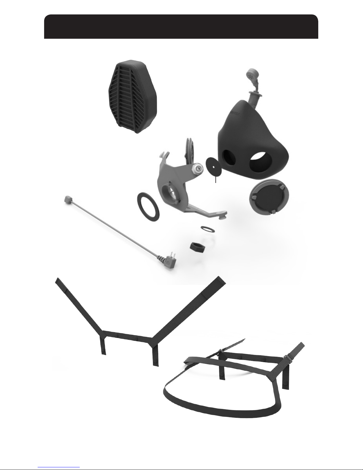
4Visually check the snaps, exhalation valves, inhalation valve, and lter gasket for signs of damage.
5Visually check the SOTR facepiece for any signs of damage.
6Check that both harnesses work properly and do not have any damage.
7Visually check the microphone and conduct operational checks of the microphone.
NOTE: If any defects are found, the damaged components should be replaced before use.
1Always start your training or operation with a new lter.
2Once the lter becomes difcult to breathe through, discard the lter* and replace with a new one.
3Visually check the lter gasket on the front of the yoke for any signs of damage.
4Replace the lter gasket after 50 lter changes (or earlier if damage is observed).
NOTE: *Dispose of the lter according to your unit’s recommendation. The lter will contain
hazardous elements and must be disposed of accordingly. Local, state, and/or federal disposal
regulations may apply.

10
REPLACEMENT PARTS
Exhalation Valve
Lock Washer*
Nut*
Inhalation
Flapper
Helmet Harness
Head Harness
Yoke
(Filter) Gasket
Filter
Communications
Cable*
Microphone*
Facepiece
*Available only on communications version.

11
REPLACEMENT PARTS
Part Name Part Number Qty Needed
per Mask
Communications Cable* GW2003-01 1
Microphone* GW2002-01 1
Lock Washer* G055-1035-01 1
Nut* GW1996-01 1
Head Harness G055-1024-02 1
Helmet Harness G055-1024-01 1
Exhalation Valve G055-1023-01 2
Inhalation Flapper G055-1033-01 1
Filter Gasket G055-1004-01 1
Particulate Filter G055-1005-02 1
Communications Yoke Assembly* G055-1003-01 1
Non-Comm. Yoke Assembly G055-1003-02 1
Communications Facepiece* G055-1041-01 1
Non-Communications Facepiece G055-1041-02 1
* Available for the communications version only, which includes a hole at the bottom of the mask for
the microphone.

12
REPLACEMENT PARTS
1REMOVE OLD INHALATION FLAPPER
While the lter is uninstalled from the front of the mask, use one nger to gently push the inhalation
apper into the mask. Gently pull the lifted portion of the apper until it becomes free. Discard the
apper accordingly.
2INSTALL NEW INHALATION FLAPPER
Align the new apper with the three anchor points on the mask and gently stretch the apper
over the anchor points until it is beneath all three points.
INHALATION FLAPPER REPLACEMENT
Old
Inhalation Flapper
New
Inhalation Flapper

REPLACEMENT PARTS
13
1REMOVE OLD EXHALATION VALVES
While rmly holding onto the exhalation valve, pull the facepiece away from the exhalation valve until a
portion of the valve becomes unseated. Continue to pull the facepiece and push the valve until the valve is
free. Dispose of the exhalation valve according to the same rules and regulations as the SOTR lter.
NOTE: Always replace both exhalation valves at the same time to ensure your mask will function properly.
2INSTALL NEW EXHALATION VALVES
Push a portion of the valve seat retention groove partially over the facepiece opening. Stretch the remainder
of the facepiece into the retention groove. Ensure that the valve seat is ush and the facepiece is fully inserted
within the valve seat retention groove so that it is sealed.
NOTE: Always install the valves so that the valve openings are facing downwards, away from the user’s eyes.
EXHALATION VALVE REPLACEMENT
Used
Exhalation Valve
New
Exhalation Valve Valve Openings

14
REPLACEMENT PARTS
1DISASSEMBLE MICROPHONE & LOCK WASHER
Unscrew the plastic nut at the base of the microphone on the outside of the yoke while maintaining
positive control of the nut and lock washer. Then pull the microphone away from the facepiece to remove.
2REASSEMBLE MICROPHONE & LOCK WASHER
To install the microphone back into the mask, rst identify the small microphone image on the microphone
and make sure that the microphone image is facing towards the user’s face. While holding the microphone
in the correct position, push the microphone threads through the inside of the facepiece and yoke
microphone hole. Place the lock washer over the microphone threads and tighten the plastic nut onto the
microphone threads.
NOTE: When tightening the plastic nut, be careful not to cross thread the base of the microphone. The nut
must be tight enough that the microphone will not rotate once installation is complete. The recommended
torque value is 60 in-oz.
MICROPHONE & LOCK WASHER REPLACEMENT
Microphone
Microphone
Image
Lock Washer
Nut

15
REPLACEMENT PARTS
1REMOVE OLD FILTER GASKET
Gently peel off the used orange gasket and discard according to all state, federal, and unit regulations.
2INSTALL NEW FILTER GASKET
Place the new gasket onto the Yoke Assembly. Be sure that all three lter lock tabs are visible.
FILTER GASKET REPLACEMENT
Used
Filter Gasket
New
Filter Gasket
Filter Lock Tab

16
REPLACEMENT PARTS
1REMOVE EXISTING YOKE ASSEMBLY
First, disassemble the microphone by following step 1 on page 14. Next, remove the inhalation
apper by following step 1 on page 12 to avoid damaging it. Lastly, starting on one inside corner,
peel the facepiece off of the inside of the yoke until it is free.
NOTE: When peeling off the facemask,
the exhalation valves will likely become
uninstalled. Follow step 2 on page 13
to reinstall.
2INSTALL REPLACEMENT YOKE ASSEMBLY
Starting at the top of the rectangular inhalation apper seat, gently pull the facepiece into the space
between the inhalation apper seat and the back of the yoke, until all four corners of the inhalation
apper seat are visible inside of the facepiece.
YOKE ASSEMBLY REPLACEMENT
Microphone
Inhalation
Flapper
Lock Washer
Facepiece
Nut
Yoke
Filter Gasket

17
REPLACEMENT PARTS
3INSPECT THE MASK AND REINSTALL MICROPHONE &
INHALATION FLAPPER
Inspect and verify that the facepiece is ush with the yoke assembly, reinstall the inhalation valve
apper (see step 2 on page 12), and ensure the exhalation valves are properly seated into the mask with
proper orientation as shown in step 2 on page 13. Next, install the microphone with locking washer and
nut by following step 2 on page 14.

18
OPERATOR NOTES

19
WARRANTY
Unless an individual product is covered by a separately issued warranty, Gentex warrants that all ballistic helmet
shells will be free from defects in material or workmanship under normal use and service for a period of ve
(5) years from the date of delivery. Unless an individual product is covered by a separately issued warranty,
Gentex warrants that all helmet components, accessories, peripherals, and parts will be free from defects in
material or workmanship under normal use and service for a period one (1) year from the date of delivery. All
repair covered by this warranty shall be performed at Gentex’s factory, or other such warranty repair facilities of
Gentex as designated by Gentex unless Gentex specically directs that repair services be performed at another
location. Any defect corrected and found to be within this scope of the warranty will be repaired by Gentex and
all charges for labor and material will be borne by Gentex. If it is determined that either no fault exists in Gentex,
or the damage to be repaired was caused by negligence of the user, its agents, employees or customers, you
agree to pay all charges associated with each such repair. No statement, recommendation or assistance made
or offered by Gentex through its representatives to the user, its agents, employees, or customers in connection
with the purpose or intended use of any Gentex’s product shall be or constitute a waiver by Gentex of any of the
provisions of this warranty or change Gentex’s liability under this warranty.
EXCEPT WHERE PROHIBITED BY LAW, THE WARRANTY DESCRIBED ABOVE CONSTITUTES THE SOLE WARRANTY
MADE BY GENTEX EITHER EXPRESSED OR IMPLIED. THERE ARE NO OTHER WARRANTIES EXPRESSED OR
IMPLIED THAT EXTEND BEYOND THE FACE HEREOF, HEREIN, INCLUDING THE IMPLIED WARRANTIES OF
MERCHANTABILITY AND FITNESS FOR A PARTICULAR PURPOSE. IN NO EVENT SHALL GENTEX BE LIABLE FOR
ANY INCIDENTAL, CONSEQUENTIAL, OR SPECIAL DAMAGES EVEN IF ADVISED OF SUCH DAMAGES, AND THE
USER, ITS AGENTS, EMPLOYEES, OR CUSTOMERS REMEDIES SHALL BE LIMITED TO SOLELY TO THE REPAIR OR
REPLACEMENT OF NONCONFORMING UNITS OR PARTS, WHICH AMOUNT SHALL NOT EXCEED THE TOTAL
PURCHASE PRICE OF THE PRODUCT UNDER WARRANTY.
Any tampering, misuse or negligence in handling or use of the product renders the warranty void. Further, the
warranty is void if, at any time, the user, its agents, employees or customers attempts to make any internal
changes to any of the components of a product; if at any time the power supplied to any part of the product
exceeds the rated tolerance; if any external device attached by the user, its agents, employees or customers
creates conditions exceeding the tolerance of the product; or if any time the serial number plate is removed or
defaced. OPERATION OF THE PRODUCTS THAT RENDERS THIS WARRANTY VOID WILL BE DEFINED TO INCLUDE
ALL OF THE POSSIBILITIES DESCRIBED IN THIS SECTION, TOGETHER WITH ANY PRACTICE THAT RESULTS IN
CONDITIONS EXCEEDING THE DESIGN TOLERANCE OF THE PRODUCTS.

Table of contents