OPTICAL SYSTEMS DESIGN
DOC ID: 10117401
OSD2155 OPERATOR MANUAL
PAGE 3
INDEX 1
1
TECHNICAL SUMMARY........................................................................................................ 5
1.1
BRIEF
DESCRIPTION ............................................................................................................ 5
1.1.1
OVERVIEW......................................................................................................................... 5
1.1.2
APPLICATIONS.................................................................................................................. 5
1.1.3
FEATURES AND BENEFITS............................................................................................. 5
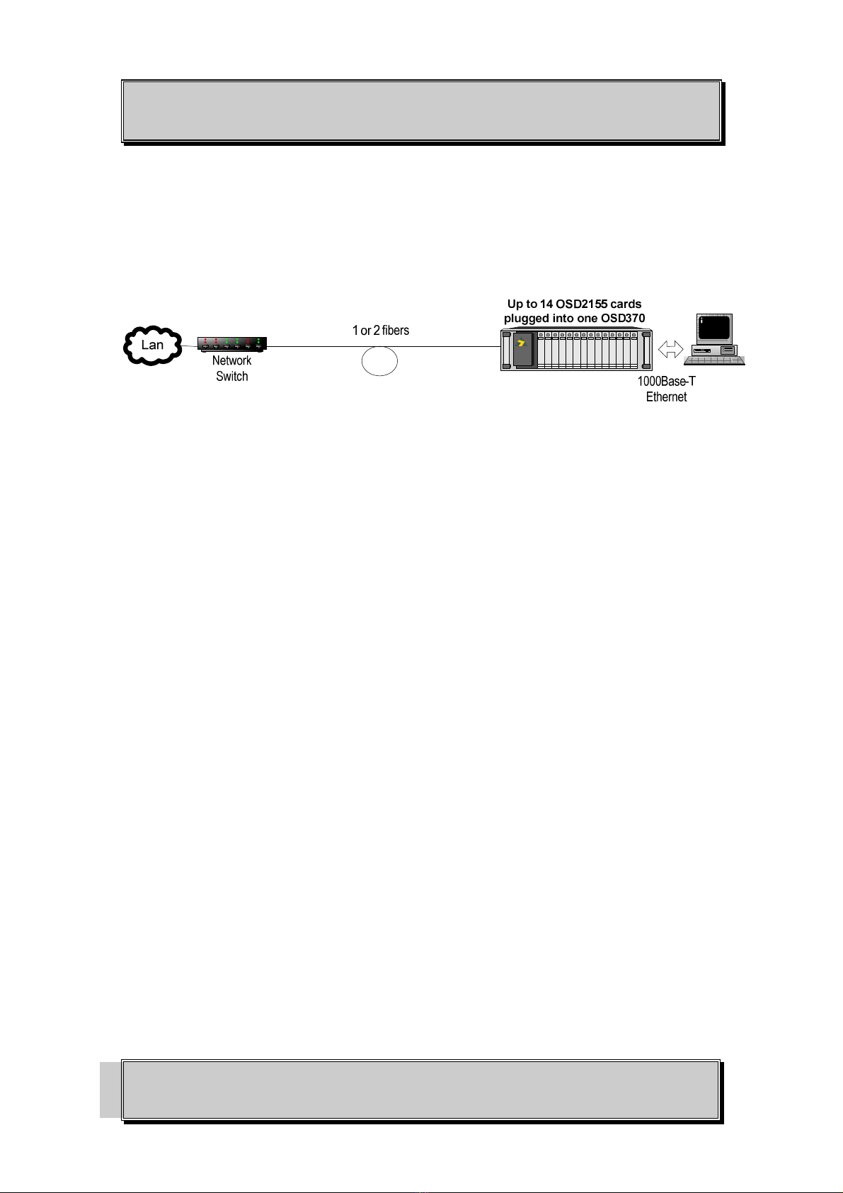
1.2
TYPICAL
CONFIGURATION................................................................................................ 6
1.3
TECHNICAL
SPECIFICATIONS ........................................................................................... 7
1.4
FRONT
PANEL ....................................................................................................................... 8
2
INSTALLATION AND OPERATION..................................................................................... 9
2.1
INTRODUCTION .................................................................................................................... 9
2.2
INSTALLATION ..................................................................................................................... 9
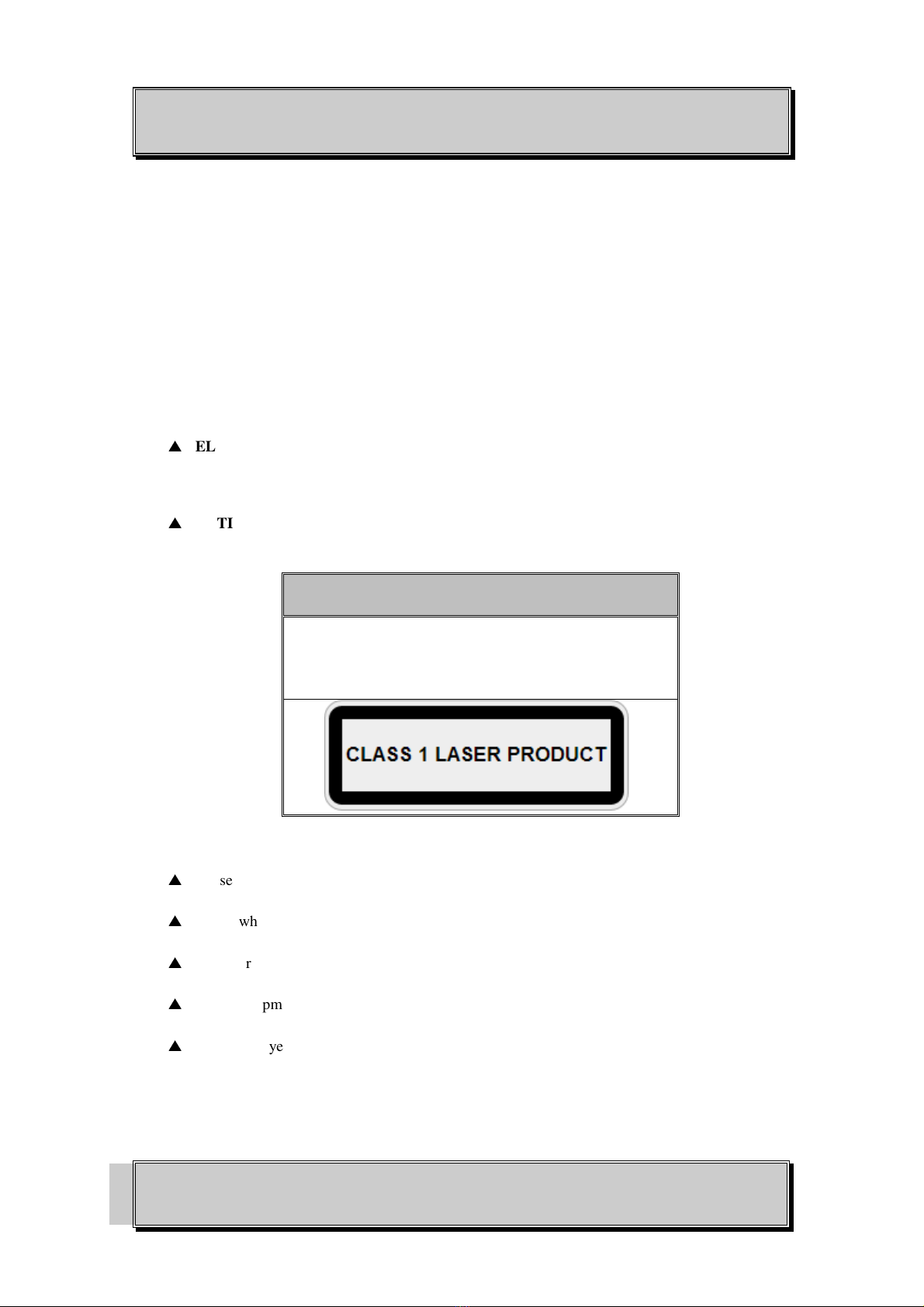
2.2.1
WARNING AND PRECAUTIONS..................................................................................... 9
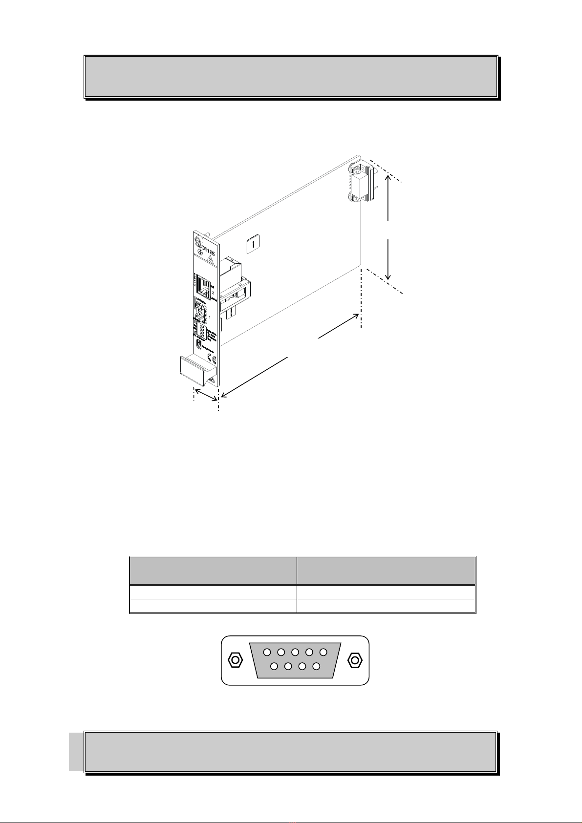
2.2.2
OSD2155 DRAWINGS AND DIMENSIONS................................................................... 10
2.2.3
POWER SUPPLY CONNECTIONS ................................................................................. 10
2.2.4
LOCATION........................................................................................................................ 11
2.2.5
FIXED RJ45 COPPER PORT PIN ASSIGNMENTS........................................................ 11
2.2.6
FITTING SFP CONNECTORS.......................................................................................... 11
2.2.7
LED INDICATORS ........................................................................................................... 12
2.2.8
CONTROLS ....................................................................................................................... 13
2.2.9
BASIC CONNECTIONS ................................................................................................... 14
2.3
LINK
LOSS
FORWARDING ................................................................................................ 15
3
MAINTENANCE...................................................................................................................... 18
3.1
INTRODUCTION .................................................................................................................. 18
3.2
EXTERNAL
INSPECTION ................................................................................................... 18
3.3
ROUTINE
MAINTENANCE................................................................................................. 18
4
WARRANTY ............................................................................................................................ 19
4.1
WARRANTY
PERIOD.......................................................................................................... 19
4.2
REPAIRS................................................................................................................................ 19
4.2.1
WARRANTY REPAIRS.................................................................................................... 19
4.2.2
OUT-OF-WARRANTY REPAIRS.................................................................................... 19
4.2.3
SITE REPAIRS .................................................................................................................. 19
4.2.4
EXCLUSIONS ................................................................................................................... 19