IFM ZZ0600 Manual

Instructions for set-up
Fluid monitoring system
Application solution
11274132 / 00 09 / 2019
UK

Fluid monitoring system - Application solution
2
Contents
1 Preliminary note � � � � � � � � � � � � � � � � � � � � � � � � � � � � � � � � � � � � � � � � � � � � � � � � � � � � � � � � � � � � � � � � � � � �3
1�1 Symbols used � � � � � � � � � � � � � � � � � � � � � � � � � � � � � � � � � � � � � � � � � � � � � � � � � � � � � � � � � � � � � � � � � �3
1�2 Further documents � � � � � � � � � � � � � � � � � � � � � � � � � � � � � � � � � � � � � � � � � � � � � � � � � � � � � � � � � � � � � �3
2 Safety instructions � � � � � � � � � � � � � � � � � � � � � � � � � � � � � � � � � � � � � � � � � � � � � � � � � � � � � � � � � � � � � � � � � �4
3 Functions and features � � � � � � � � � � � � � � � � � � � � � � � � � � � � � � � � � � � � � � � � � � � � � � � � � � � � � � � � � � � � � � �4
4 Function � � � � � � � � � � � � � � � � � � � � � � � � � � � � � � � � � � � � � � � � � � � � � � � � � � � � � � � � � � � � � � � � � � � � � � � � � �5
4�1 Fluid monitoring system � � � � � � � � � � � � � � � � � � � � � � � � � � � � � � � � � � � � � � � � � � � � � � � � � � � � � � � � � �5
4�2 IO-Link masters � � � � � � � � � � � � � � � � � � � � � � � � � � � � � � � � � � � � � � � � � � � � � � � � � � � � � � � � � � � � � � � �5
4�3 Industrial PC � � � � � � � � � � � � � � � � � � � � � � � � � � � � � � � � � � � � � � � � � � � � � � � � � � � � � � � � � � � � � � � � � � �5
5 Installation� � � � � � � � � � � � � � � � � � � � � � � � � � � � � � � � � � � � � � � � � � � � � � � � � � � � � � � � � � � � � � � � � � � � � � � � �7
5�1 Fluid monitoring system � � � � � � � � � � � � � � � � � � � � � � � � � � � � � � � � � � � � � � � � � � � � � � � � � � � � � � � � � �7
5�2 IO-Link master � � � � � � � � � � � � � � � � � � � � � � � � � � � � � � � � � � � � � � � � � � � � � � � � � � � � � � � � � � � � � � � � �7
5�3 Power supply � � � � � � � � � � � � � � � � � � � � � � � � � � � � � � � � � � � � � � � � � � � � � � � � � � � � � � � � � � � � � � � � � �7
5�4 Industrial PC � � � � � � � � � � � � � � � � � � � � � � � � � � � � � � � � � � � � � � � � � � � � � � � � � � � � � � � � � � � � � � � � � � �7
6 Electrical connection� � � � � � � � � � � � � � � � � � � � � � � � � � � � � � � � � � � � � � � � � � � � � � � � � � � � � � � � � � � � � � � � �7
6�1 Pin assignment of the IO-Link master � � � � � � � � � � � � � � � � � � � � � � � � � � � � � � � � � � � � � � � � � � � � � � �8
6�2 Wiring diagram industrial PC � � � � � � � � � � � � � � � � � � � � � � � � � � � � � � � � � � � � � � � � � � � � � � � � � � � � � �8
7 Set-up � � � � � � � � � � � � � � � � � � � � � � � � � � � � � � � � � � � � � � � � � � � � � � � � � � � � � � � � � � � � � � � � � � � � � � � � � � � �8
7�1 Set up the industrial PC � � � � � � � � � � � � � � � � � � � � � � � � � � � � � � � � � � � � � � � � � � � � � � � � � � � � � � � � � �9
7�1�1 Option 1: Local access � � � � � � � � � � � � � � � � � � � � � � � � � � � � � � � � � � � � � � � � � � � � � � � � � � � � � � �9
7�1�2 Option 2: Remote access � � � � � � � � � � � � � � � � � � � � � � � � � � � � � � � � � � � � � � � � � � � � � � � � � � � � �9
7�2 Create a backup copy of the operating system � � � � � � � � � � � � � � � � � � � � � � � � � � � � � � � � � � � � � � � �9
7�3 Set up LR DEVICE � � � � � � � � � � � � � � � � � � � � � � � � � � � � � � � � � � � � � � � � � � � � � � � � � � � � � � � � � � � � �10
7�3�1 Configure the interface to the IO-Link master� � � � � � � � � � � � � � � � � � � � � � � � � � � � � � � � � � � � �10
7�3�2 Configure the interface to the LR SMARTOBSERVER � � � � � � � � � � � � � � � � � � � � � � � � � � � � �10
7�4 Adapt the calculation of the heat quantity� � � � � � � � � � � � � � � � � � � � � � � � � � � � � � � � � � � � � � � � � � � � 11
8 Parameter setting � � � � � � � � � � � � � � � � � � � � � � � � � � � � � � � � � � � � � � � � � � � � � � � � � � � � � � � � � � � � � � � � � � 11
8�1 Change limit values and switch points � � � � � � � � � � � � � � � � � � � � � � � � � � � � � � � � � � � � � � � � � � � � � � 11
9 Operation � � � � � � � � � � � � � � � � � � � � � � � � � � � � � � � � � � � � � � � � � � � � � � � � � � � � � � � � � � � � � � � � � � � � � � � �12
9�1 Monitor the process data � � � � � � � � � � � � � � � � � � � � � � � � � � � � � � � � � � � � � � � � � � � � � � � � � � � � � � � �12

3
Fluid monitoring system - Application solution
UK
1 Preliminary note
You will find detailed instructions, technical data, approvals and further information using the QR
code on the individual units / packagings or at www�ifm�com�
1.1 Symbols used
►
Instruction
>
Reaction, result
[…]
Designation of keys, buttons or indications
→
Cross-reference
Important note
Non-compliance may result in malfunction or interference�
Information
Supplementary note�
1.2 Further documents
●Quick reference guide fluid monitoring system
●Operating instructions flow meter
●Operating instructions temperature transmitter
●Operating instructions IO-Link masters
●Operating instructions power supply
●Operating instructions Ethernet switch
●Software manual LR DEVICE
●Software manual LR SMARTOBSERVER
The documents can be downloaded at: www�ifm�com

Fluid monitoring system - Application solution
4
2 Safety instructions
●The devices described are integrated into a system as components�
– The system manufacturer is responsible for the safety of the system�
– The system creator undertakes to perform a risk assessment and to create documentation in
accordance with legal and normative requirements to be provided to the operator and user of the
system� This documentation must contain all necessary information and safety instructions for the
operator, the user and, if applicable, for any service personnel authorised by the manufacturer of
the system�
– The system manufacturer is responsible for the functioning of the application programs�
●Read this document before setting up the product and keep it during the entire service life�
●The product must be suitable for the corresponding applications and environmental conditions without
any restrictions�
● Only use the product for its intended purpose (→ 3 Functions and features)
● Only use the product for permissible media (→ Technical data).
●If the operating instructions or the technical data are not adhered to, personal injury and/or damage to
property may occur�
●The manufacturer assumes no liability or warranty for any consequences caused by tampering with
the product or incorrect use by the operator�
●Installation, electrical connection, set-up, operation and maintenance of the product must be carried
out by qualified personnel authorised by the machine operator�
●Protect units and cables against damage�
►Read the instructions of the individual components of the application package before use�
3 Functions and features
The product package is used to monitor cooling water systems�
It allows the detection of malfunctions such as soiling, flow disturbances, leakages or loss of a welding tip�
The sensors of the fluid monitoring system detect the process values flow velocity, flow quantity,
consumed quantity and medium temperature and transmit these process values to an IO-Link master via
an IO-Link interface�
The following applies to the SM6000 flow meter:
The device complies with the Pressure Equipment Directive and is designed and manufactured for
group 2 fluids in accordance with the sound engineering practice� Use of media from group 1 fluids
on request�

5
Fluid monitoring system - Application solution
UK
4 Function
4.1 Fluid monitoring system
The ZZ0600 fluid monitoring system contains the following components:
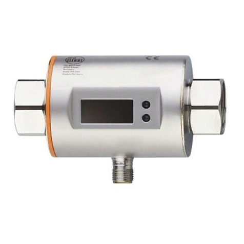
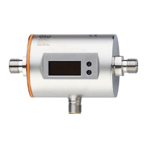
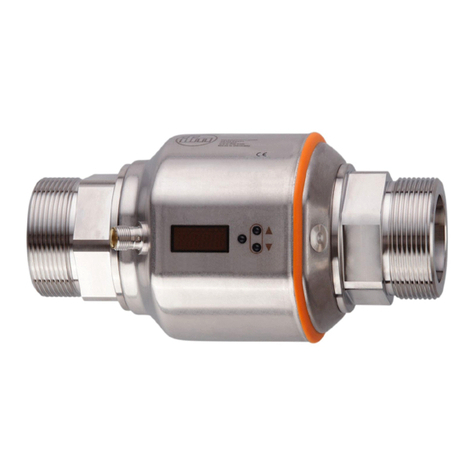
●SM6000 flow meter for monitoring and display of the flow temperature and the cooling water
volumetric flow quantity� The setting of 2 switch points allows the detection of overflow (leakage / burst
pipes / worn caps).
●Line regulator valve to regulate the volumetric flow quantity
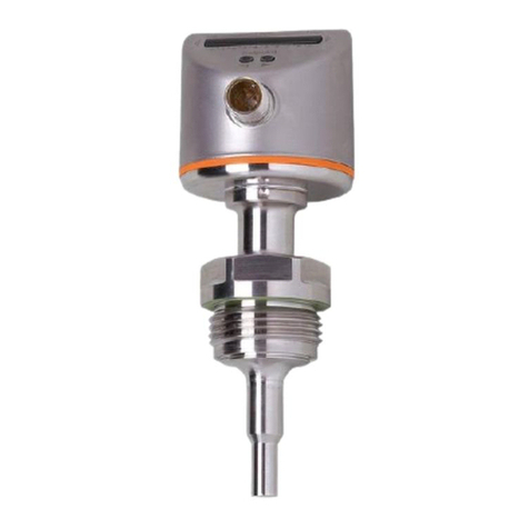
●TA2405 temperature sensor to monitor the return temperature
The fluid monitoring system transfers the process values to an IO-Link master via the IO-Link interface�
The parameters are set using the LR DEVICE parameter setting software�
4.2 IO-Link masters
The IO-Link master serves as a gateway for the process data of the connected sensors� The IO-Link
master enables setting of the parameters of the connected sensors via the LR DEVICE parameter setting
software�
4.3 Industrial PC
The industrial PC offers the following functions:
●Parameter setting of the IO-Link master and the connected sensors with LR DEVICE
●Monitoring of the process data of the fluid monitoring system with LR SMARTOBSERVER

Fluid monitoring system - Application solution
6
A
B
LR DEVICE
LR SMARTOBSERVER
2
1
ZZ0600
3
4
Fig� 1: Application solution overview
A: Preconfigured industrial PC
B: Application package consisting of:
1: Power supply
2: AL13nn IO-Link master
3: SM6000 flow meter
4: TA2405 temperature sensor

7
Fluid monitoring system - Application solution
UK
5 Installation
►Disconnect the power of the machine before installation�
►Adhere to the instructions enclosed to the individual devices�
5.1 Fluid monitoring system
►Mount the fluid monitoring system in the cooling water process�
► Adhere to the flow direction during installation (black arrow mark).
5.2 IO-Link master
►Fix the IO-Link master to a flat installation surface�
►Use 2 M5 mounting screws and washers for fastening�Tightening torque: 1�8 Nm�
5.3 Power supply
►Integrate the power supply into the control cabinet� The following has to be observed:
– Suited for DIN rails according to EN 60715 with a height of 7�5 or 15 mm�
– Align the input terminals downwards�
– In case of continuous full load adhere to the following installation distances:
Left / right: 5 mm (15 mm for adjacent heat sources)
Top: 40 mm, bottom 20 mm from the device�
The device is rated for convection cooling�
►Do not impede the air circulation� Adhere to installation distances�
5.4 Industrial PC
►Install the industrial PC in the control cabinet, taking the following into account :
– Mount the industrial PC on a flat mounting surface�
– Use 4 M5 mounting screws and washers for fastening�
The device is rated for convection cooling�
►Do not impede the air circulation� Adhere to installation distances�
6 Electrical connection
The unit must be connected by a qualified electrician�
►Observe the national and international regulations for the installation of electrical equipment�
►Adhere to the instructions enclosed to the individual devices�
►Disconnect power�
1� Connect the sensors of the fluid monitoring system to the IO-Link master�
2� Connect the IO-Link master to the secondary side of the power supply�
3� Connect the IO-Link master to the Ethernet interface 1 of the industrial PC via the IoT interface�
4� Connect the industrial PC to the secondary side of the power supply�
5� Connect the primary side of the power supply unit to the voltage supply�

Fluid monitoring system - Application solution
8
6.1 Pin assignment of the IO-Link master
AL1300 / AL1320 / AL1330 / AL1340
21
43
65
87
1: Fieldbus (optional)
2: Fieldbus (optional)
3: Power supply
4: IoT interface to the industrial PC with LR DEVICE
5: SM6000
6: TA2405
7: not connected
8: not connected
AL1350
21
3
54
76
1: IoT interface to the industrial PC with LR DEVICE
2: not connected
3: Power supply
4: SM6000
5: TA2405
6: not connected
7: not connected
6.2 Wiring diagram industrial PC
12345 6 7
V+V-
1: Power supply
2: Display port
3: VGA socket
4: HDMI interface
5: Ethernet interface 2
6: Ethernet interface 1
7: USB ports
7 Set-up
When the operating voltage has been switched on, the components of the application solution work
with the factory settings. The LEDs show the status of the devices and interfaces (→ Instructions of the
individual components).

9
Fluid monitoring system - Application solution
UK
7.1 Set up the industrial PC
The operating system Windows 10 and the software components LR DEVICE, LR AGENT and
LR SMARTOBSERVER are pre-installed on the industrial PC�
The industrial PC has 2 Ethernet interfaces� Interface 1 is used to connect the industrial PC to the IoT
network� Interface 2 allows the user to access the Windows user interface of the industrial PC�
Login details for the industrial PC:
• user: admin
• password: admin
Factory settings of the industrial PC's Ethernet interfaces:
Parameters Ethernet interface 1 Ethernet interface 2
IP address 192�168�0�50 192�168�2�50
Subnet mask 255�255�255�0 255�255�255�0
Gateway IP address 0�0�0�0 0�0�0�0
There are two options for setting up and operating the industrial PC (→ 7.1.1; → 7.1.2).
7.1.1 Option 1: Local access
The user accesses the user interface of the industrial PC via an operator terminal on the control cabinet�
►Connect the monitor to the display port, VGA socket or HDMI interface�
►Connect the mouse and keyboard to USB ports�
►Start the industrial PC�
> The Windows login screen appears�
►Enter the login details and confirm with [Enter]�
> The Windows desktop interface of the industrial PC appears�
7.1.2 Option 2: Remote access
The user accesses the user interface of the industrial PC via a remote desktop connection� For remote
access, the Ethernet interfaces of the industrial and local PC must be configured for the same IP address
range�
►Connect the local PC to Ethernet interface 2 of the industrial PC�
►Start the industrial PC�
On the local PC:
►[Control Panel] > [Network and Internet] > [Network and Sharing Center]
►Adapt the Ethernet adapter settings to the IP address range of the industrial PC's Ethernet interface 2�
> The local PC can access the Windows user interface of the industrial PC�
►Start the Windows app "Remote Desktop Connection"�
►Enter the IP address of the industrial PC's network interface 2 and confirm with [Enter]�
> The local PC establishes a connection to the industrial PC�
> The Windows login screen appears�
►Enter the login details and confirm with [Enter]�
> The Windows desktop interface of the industrial PC appears�
7.2 Create a backup copy of the operating system
ifm recommends you to create a backup copy of the Windows operating system before continuing to work
with the industrial PC�
On the industrial PC:

Fluid monitoring system - Application solution
10
► [Control Panel] > [All Control Panel Items] > [Backup and Restore (Windows 7)]
►Click on [Create a system image]�
> A dialogue window appears�
►Select the destination for the backup copy�
►Confirm the selection and start the backup�
> Windows creates a backup copy of the system�
7.3 Set up LR DEVICE
LR DEVICE allows the parameter setting of the IO-Link master and the connected sensors�
►Start LR DEVICE�
►The user interface of the LR DEVICE appears�
7.3.1 Congure the interface to the IO-Link master
For parameter setting, the IoT interface of the IO-Link master and the Ethernet interface 1 of the industrial
PC must be configured for the same subnet�
In LR DEVICE:
►Click on the symbol [
IO-LINK
] to scan the network for available devices�
> LR DEVICE finds the connected IO-Link master�
►In the [ONLINE] area: Click on the IO-Link master�
> The detail window shows the IT settings of the IoT interface�
►Change the following parameters:
Parameter Value
IP address 192�168�0�1
Subnet mask 255�255�255�0
Default gateway IP address 0�0�0�0
►Click on the symbol [
IO-LINK
] to write the changed values to the IO-Link master�
> LR DEVICE reads the unit with the changed values once again�
> LR DEVICE has access to the parameters of the connected sensors (→ 8 Parameter setting)�
7.3.2 Congure the interface to the LR SMARTOBSERVER
To visualise the process data of the fluid monitoring system in the monitoring software, the interface of
the LR SMARTOBSERVER must be set in the IO-Link master� In addition, the user can assign a unique
name (application tag) to the application package to be displayed in the LR SMARTOBSERVER.

11
Fluid monitoring system - Application solution
UK
In LR DEVICE:
►In the [ONLINE] area: Click on the IO-Link master�
> The detail window shows the available parameters of the IO-Link master�
►Change the following parameters in the [IoT] menu:
Parameters Value
IP address LR Agent or SMARTOBSERVER 192�168�0�50
Port LR Agent or SMARTOBSERVER 35101
Interval LR Agent or SMARTOBSERVER 15000
Application tag Fluid Monitoring System 1
►Click on the symbol [
IO-LINK
] to write the changed values to the IO-Link master�
7.4 Adapt the calculation of the heat quantity
In the factory settings, the calculation of the heat quantity is rated for the coolant "water"� If a different
coolant is used, execute the following actions:
On the industrial PC:
►Open the following directory in the file explorer:C:\Program Files\ifm electronic\LR4\LRAgent\
LRAgent_customized\Config\FMS
►Open the file "Parameters" using the text editor�
►Change the values of the following parameters according to the selected coolant:
Parameters Description
SpecificHeatCapacity Specific heat capacity of the coolant (e.g. 4.18)
Density Density of the coolant (e.g. 995.0)
►Save and close the file�
►Open Windows application "Services"�
► Right mouse click on the service "LR Agent (FMS)"
►Select the command "Restart" in the context menu�
> The service is restarted�
> Changed parameter values are used to calculate the heat quantity�
8 Parameter setting
The parameters can be set before installation or during operation via the IO-Link interface�
If you change parameters during operation, this will influence the function of the plant�
►Ensure that there will be no malfunctions in your plant�
During parameter setting the sensors remain in the operating mode� They continue to monitor with the
existing parameter until the parameter setting has been completed�
The sensors' IODD at www�ifm�com contains a complete list of adjustable parameters�
8.1 Change limit values and switch points
Adjust the limit values and switch points of the sensors:
In LR DEVICE:
►Click on the symbol [
IO-LINK
] to scan the network for available devices�
> LR DEVICE finds the connected IO-Link master�

Fluid monitoring system - Application solution
12
►In the [ONLINE] area: Click on the IO-Link master found�
> LR DEVICE shows the sensors connected to the ports�
► Click on Port ([P1: SM6000] or [P2: TA2405]).
> Adjustable parameters of the connected sensor are displayed�
►Change limit values and switch points�
►Click on the symbol [
IO-LINK
] to write the changed parameter values to the sensor�
> The sensor functions with the changed parameter values�
9 Operation
9.1 Monitor the process data
The LR SMARTOBSERVER enables the monitoring of process data� The LR SMARTOBSERVER is
preconfigured for the "fluid monitoring system" application solution�
Login details for the LR SMARTOBSERVER:
• user name: test
• password: test
►Start the LR SMARTOBSERVER�
> The login screen appears�
►Enter the user name and password and confirm with [OK]�
> The user interface of the LR SMARTOBSERVER appears�

13
Fluid monitoring system - Application solution
UK
In the [Cockpit] section:
►Under [FMS]: Select the application tag of the requested fluid monitoring system (e�g� fluid monitoring
system 1-1).
►In the status line: Select the [AUTO] tab�
> The window shows the current process values of the selected fluid monitoring system�
Explanation:
Display Description Source
Cooling Power Cooling power (in kW) calculated from the process data
SM6000-Flow-FL Flow (in l/min) SM6000
SM6000-Temp-FL Temperature in the supply line (in °C) SM6000
SM6000-Totalizer-FL Volumetric flow quantity since the last reset (in l) SM6000
TA2405-Temp-FL Temperature in the return line (in °C) TA2405
Other manuals for ZZ0600
1
Table of contents
Other IFM Measuring Instrument manuals

IFM
IFM efector300 SD0523 User manual

IFM
IFM SI0555 User manual

IFM
IFM SM4x00 User manual

IFM
IFM SD26 Series User manual

IFM
IFM efector 300 SD2001 User manual

IFM
IFM SDG082 User manual

IFM
IFM Efector 300 SL5204 User manual

IFM
IFM efector 300 SI0558 User manual

IFM
IFM DD111S User manual

IFM
IFM efector300 VS3000 User manual
Popular Measuring Instrument manuals by other brands

Emerson
Emerson Micro Motion quick start guide

ARJAY ENGINEERING
ARJAY ENGINEERING 4500-RMS user manual

Honeywell
Honeywell Morley-IAS MI-IM10 Installation and maintenance instructions

GE
GE Intellix BMT 330 installation manual

ATOMSTACK
ATOMSTACK R30 installation manual

STI
STI CMCP810 Series quick start guide