Control central and
paging desk
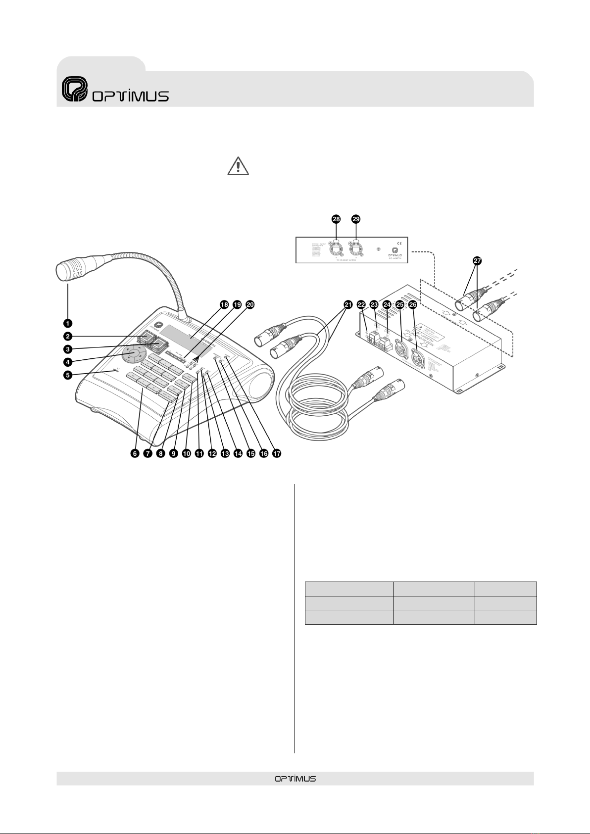
(7) GONG+TALK key
Used to send a live paging preceded by a GONG.
First, select the zones to which the
announcement is to be sent. Hold the key down
while you speak.
(8) TALK button
Used to send a live voice announcement. First,
select the zones to which the announcement is to
be sent. Hold the key down while you speak.
(9) REP key
Key for repetition of the last live voice message
sent.
(10) PLAY key
Used to send a pre-recorded message. First,
select the message as well as the zones to which
it is to be sent.
(11) PLAY indicator
Indicates that a pre-recorded message is being
played.
(12) TALK indicator
When it lights, it indicates that you can begin to
make the announcement.
(13) GONG indicator
When it lights, it indicates that the desk is
generating the GONG.
(14) BUSY indicator
When it lights, it indicates that the system is
busy.
(15) EMERGENCY MODE indicator
When it lights, it indicates that the desk is in
emergency mode.
(16) ALARM indicator
Indicates an alarm. Software configurable.
(17) POWER indicator
Indicates that the desk is receiving power.
(18) Display
(19) MIC LEVEL indicator
Indicates the audio level of the microphone, the
MP3 messages and the music input of the desk.
The LED marked Peak indicates that the signal is
saturated. This LED should not light.
(20) ETH A and B indicators
LINK: When lit, it indicates connection to the
network through the ETHERNET A or B inputs.
ACT: When it blinks, it indicates that data is
being sent or received through the ETHERNET A
or B inputs.
(21) Interconnection cables between the
desk and the junction box.
(22) POWER indicator
Indicates that the interconnection box is
receiving power.
(23) POWER SUPPLY 1 input
24 V DC input to power the desk.
(24) POWER SUPPLY 2 input
24 V DC input to power the desk. The power
supply inputs have been doubled, so that if—on
account of safety regulations—the installation so
requires, two independent power supplies can be
connected.
(25) Connector A “To OPTIMUS
Equipment”
Connection A between the desk and the
CC-600ETH connection box.
(26) Connector B “To OPTIMUS
Equipment”
Connection B between the desk and the
CC-600ETH connection box.
(27) ETHERCON aerial connectors for
connection to the IP network.
(28) Connector B “To Ethernet Switch”
Used, in a redundant network, as a secondary
connection to the ETHERNET network.
(29) Connector A “To Ethernet Switch”
Used for connection of the desk to the IP
network.