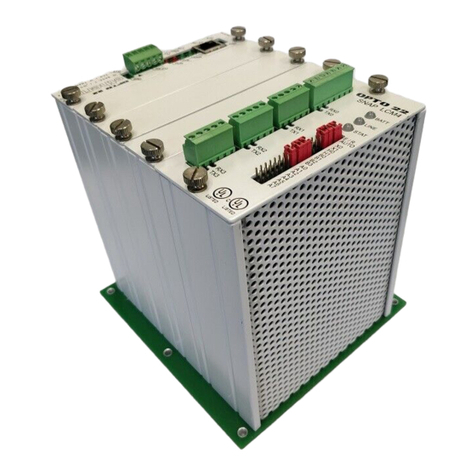
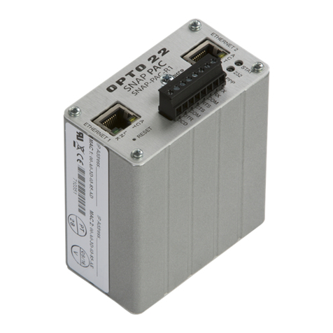
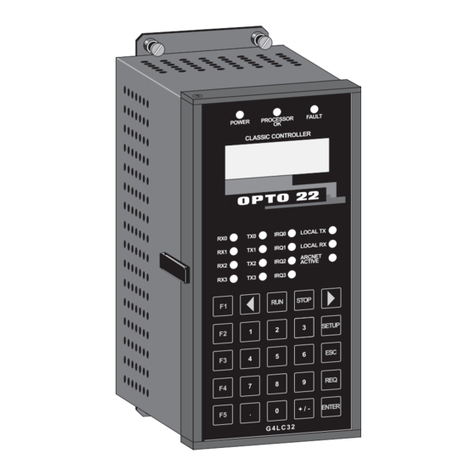
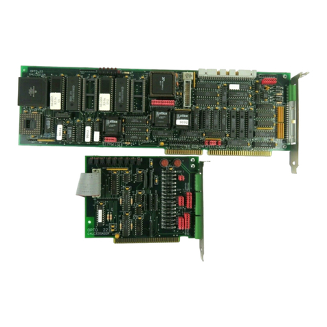
OPTO 22 SNAP-PAC-S1 User manual

SNAP PAC S-SERIES CONTROLLER
USER’S GUIDE
SNAP-PAC-S1
SNAP-PAC-S2
Form 1592-071126—November, 2007
43044 Business Park Drive • Temecula • CA 92590-3614
Phone: 800-321-OPTO (6786) or 951-695-3000
Fax: 800-832-OPTO (6786) or 951-695-2712
www.opto22.com
Product Support Services
800-TEK-OPTO (835-6786) or 951-695-3080
Fax: 951-695-3017
Email: support@opto22.com
Web: support.opto22.com

SNAP PAC S-Series User’s Guide
ii
SNAP PAC S-Series User’s Guide
Form 1592-071126—November, 2007
Copyright © 2005–2007 Opto 22.
All rights reserved.
Printed in the United States of America.
The information in this manual has been checked carefully and is believed to be accurate; however, Opto 22 assumes no
responsibility for possible inaccuracies or omissions. Specifications are subject to change without notice.
Opto 22 warrants all of its products to be free from defects in material or workmanship for 30 months from the
manufacturing date code. This warranty is limited to the original cost of the unit only and does not cover installation, labor, or
any other contingent costs. Opto 22 I/O modules and solid-state relays with date codes of 1/96 or later are guaranteed for life.
This lifetime warranty excludes reed relay, SNAP serial communication modules, SNAP PID modules, and modules that
contain mechanical contacts or switches. Opto 22 does not warrant any product, components, or parts not manufactured by
Opto 22; for these items, the warranty from the original manufacturer applies. These products include, but are not limited to,
OptoTerminal-G70, OptoTerminal-G75, and Sony Ericsson GT-48; see the product data sheet for specific warranty
information. Refer to Opto 22 form number 1042 for complete warranty information.
Cyrano, Opto 22 FactoryFloor, Optomux, and Pamux are registered trademarks of Opto 22. Generation 4, ioControl, ioDisplay,
ioManager, ioProject, ioUtilities, mistic, Nvio, Nvio.net Web Portal, OptoConnect, OptoControl, OptoDataLink, OptoDisplay,
OptoOPCServer, OptoScript, OptoServer, OptoTerminal, OptoUtilities, PAC Control, PAC Display, PAC Manager, PAC Project,
SNAP Ethernet I/O, SNAP I/O, SNAP OEM I/O, SNAP PAC System, SNAP Simple I/O, SNAP Ultimate I/O, and SNAP Wireless LAN
I/O are trademarks of Opto 22.
ActiveX, JScript, Microsoft, MS-DOS, VBScript, Visual Basic, Visual C++, and Windows are either registered trademarks or
trademarks of Microsoft Corporation in the United States and other countries. Linux is a registered trademark of Linus
Torvalds. Unicenter is a registered trademark of Computer Associates International, Inc. ARCNET is a registered trademark of
Datapoint Corporation. Modbus is a registered trademark of Schneider Electric. Wiegand is a registered trademark of Sensor
Engineering Corporation. Nokia, Nokia M2M Platform, Nokia M2M Gateway Software, and Nokia 31 GSM Connectivity
Terminal are trademarks or registered trademarks of Nokia Corporation. Sony is a trademark of Sony Corporation. Ericsson is a
trademark of Telefonaktiebolaget LM Ericsson.
All other brand or product names are trademarks or registered trademarks of their respective companies or organizations.

SNAP PAC S-Series User’s Guide iii
iii
Table of Contents
Chapter 1: Overview . . . . . . . . . . . . . . . . . . . . . . . . . . . . . . . . . . . . . . . . . . . . . . . . . . . . . 1
Introduction. . . . . . . . . . . . . . . . . . . . . . . . . . . . . . . . . . . . . . . . . . . . . . . . . . . . . . . . . . . . . . . . . . . . . . . . . . . . . . . . 1
Ethernet Communication . . . . . . . . . . . . . . . . . . . . . . . . . . . . . . . . . . . . . . . . . . . . . . . . . . . . . . . . . . . . . . . . 1
Serial Communication . . . . . . . . . . . . . . . . . . . . . . . . . . . . . . . . . . . . . . . . . . . . . . . . . . . . . . . . . . . . . . . . . . 2
Backward Compatibility . . . . . . . . . . . . . . . . . . . . . . . . . . . . . . . . . . . . . . . . . . . . . . . . . . . . . . . . . . . . . . . . . 2
Software. . . . . . . . . . . . . . . . . . . . . . . . . . . . . . . . . . . . . . . . . . . . . . . . . . . . . . . . . . . . . . . . . . . . . . . . . . . . . . . . . . . 3
Software Availability . . . . . . . . . . . . . . . . . . . . . . . . . . . . . . . . . . . . . . . . . . . . . . . . . . . . . . . . . . . . . . . . . . . . 4
Architectural Diagrams . . . . . . . . . . . . . . . . . . . . . . . . . . . . . . . . . . . . . . . . . . . . . . . . . . . . . . . . . . . . . . . . . . . . . . 4
Connections to Serial-based I/O Units . . . . . . . . . . . . . . . . . . . . . . . . . . . . . . . . . . . . . . . . . . . . . . . . . . . . . 5
SNAP-PAC-S2 Connections to Serial-based I/O Units . . . . . . . . . . . . . . . . . . . . . . . . . . . . . . . . . . . . . . . . 6
Ethernet Link Redundancy . . . . . . . . . . . . . . . . . . . . . . . . . . . . . . . . . . . . . . . . . . . . . . . . . . . . . . . . . . . . . . . 7
Remote Host and I/O Unit Connections Using PPP . . . . . . . . . . . . . . . . . . . . . . . . . . . . . . . . . . . . . . . . . . 8
Ethernet Connections to Host and I/O Units . . . . . . . . . . . . . . . . . . . . . . . . . . . . . . . . . . . . . . . . . . . . . . . . 9
About This Guide . . . . . . . . . . . . . . . . . . . . . . . . . . . . . . . . . . . . . . . . . . . . . . . . . . . . . . . . . . . . . . . . . . . . . . . . . 10
Related Documentation . . . . . . . . . . . . . . . . . . . . . . . . . . . . . . . . . . . . . . . . . . . . . . . . . . . . . . . . . . . . . . . . . . . 10
For Help . . . . . . . . . . . . . . . . . . . . . . . . . . . . . . . . . . . . . . . . . . . . . . . . . . . . . . . . . . . . . . . . . . . . . . . . . . . . . . . . . 11
Chapter 2: Quick Start . . . . . . . . . . . . . . . . . . . . . . . . . . . . . . . . . . . . . . . . . . . . . . . . . .13
Installing and Configuring the Controller. . . . . . . . . . . . . . . . . . . . . . . . . . . . . . . . . . . . . . . . . . . . . . . . . . . . . 13
What You Will Need . . . . . . . . . . . . . . . . . . . . . . . . . . . . . . . . . . . . . . . . . . . . . . . . . . . . . . . . . . . . . . . . . . . 13
Installing Software . . . . . . . . . . . . . . . . . . . . . . . . . . . . . . . . . . . . . . . . . . . . . . . . . . . . . . . . . . . . . . . . . . . . . 13
Power Supply Recommendations . . . . . . . . . . . . . . . . . . . . . . . . . . . . . . . . . . . . . . . . . . . . . . . . . . . . . . . 14
Change to SNAP-PAC-S1 Power Input Range . . . . . . . . . . . . . . . . . . . . . . . . . . . . . . . . . . . . . . . . . . . . . 14
Installing Hardware . . . . . . . . . . . . . . . . . . . . . . . . . . . . . . . . . . . . . . . . . . . . . . . . . . . . . . . . . . . . . . . . . . . . 14
RS-232 and RS-485 Serial Networking . . . . . . . . . . . . . . . . . . . . . . . . . . . . . . . . . . . . . . . . . . . . . . . . . . . 15
RS-232 Connections . . . . . . . . . . . . . . . . . . . . . . . . . . . . . . . . . . . . . . . . . . . . . . . . . . . . . . . . . . . . . . . 15
Attaching the Modem to the Controller . . . . . . . . . . . . . . . . . . . . . . . . . . . . . . . . . . . . . . . . . . . . . .16

SNAP PAC S-Series User’s Guide
iv
RS-485 Connections . . . . . . . . . . . . . . . . . . . . . . . . . . . . . . . . . . . . . . . . . . . . . . . . . . . . . . . . . . . . . . .16
Wiring the 10-pin Serial Connector on the SNAP-PAC-S1 . . . . . . . . . . . . . . . . . . . . . . . . . . . . . . .18
Wiring the 7-pin Serial Connector on the SNAP-PAC-S2 . . . . . . . . . . . . . . . . . . . . . . . . . . . . . . . .18
Serial Wiring Diagrams . . . . . . . . . . . . . . . . . . . . . . . . . . . . . . . . . . . . . . . . . . . . . . . . . . . . . . . . . . . . .19
Assigning an IP Address . . . . . . . . . . . . . . . . . . . . . . . . . . . . . . . . . . . . . . . . . . . . . . . . . . . . . . . . . . . . . . . .21
Assigning Serial Ports on the SNAP-PAC-S2 . . . . . . . . . . . . . . . . . . . . . . . . . . . . . . . . . . . . . . . . . . . . . . .21
Mounting the Controller . . . . . . . . . . . . . . . . . . . . . . . . . . . . . . . . . . . . . . . . . . . . . . . . . . . . . . . . . . . . . . . .21
Panel Mounting and Dimensions . . . . . . . . . . . . . . . . . . . . . . . . . . . . . . . . . . . . . . . . . . . . . . . . . . . .22
DIN-Rail Mounting and Dimensions . . . . . . . . . . . . . . . . . . . . . . . . . . . . . . . . . . . . . . . . . . . . . . . . .24
About the Controller’s Memory Map. . . . . . . . . . . . . . . . . . . . . . . . . . . . . . . . . . . . . . . . . . . . . . . . . . . . . . . . . 26
Using Data for Peer-to-Peer Communication . . . . . . . . . . . . . . . . . . . . . . . . . . . . . . . . . . . . . . . . . . . . . .26
What’s Next? . . . . . . . . . . . . . . . . . . . . . . . . . . . . . . . . . . . . . . . . . . . . . . . . . . . . . . . . . . . . . . . . . . . . . . . . . . . . . 27
Chapter 3: Maintenance and Troubleshooting . . . . . . . . . . . . . . . . . . . . . . . . . . . 29
Troubleshooting . . . . . . . . . . . . . . . . . . . . . . . . . . . . . . . . . . . . . . . . . . . . . . . . . . . . . . . . . . . . . . . . . . . . . . . . . . 29
Checking Power . . . . . . . . . . . . . . . . . . . . . . . . . . . . . . . . . . . . . . . . . . . . . . . . . . . . . . . . . . . . . . . . . . . . . . .29
Communicating on an Ethernet Network . . . . . . . . . . . . . . . . . . . . . . . . . . . . . . . . . . . . . . . . . . . . . . . . .30
Pinging the Controller . . . . . . . . . . . . . . . . . . . . . . . . . . . . . . . . . . . . . . . . . . . . . . . . . . . . . . . . . . . . . .30
Solving Network Problems . . . . . . . . . . . . . . . . . . . . . . . . . . . . . . . . . . . . . . . . . . . . . . . . . . . . . . . . . . . . . .31
Create a Network Diagram . . . . . . . . . . . . . . . . . . . . . . . . . . . . . . . . . . . . . . . . . . . . . . . . . . . . . . . . . .31
Check Ethernet Errors . . . . . . . . . . . . . . . . . . . . . . . . . . . . . . . . . . . . . . . . . . . . . . . . . . . . . . . . . . . . . .31
Analyze Communication Packets . . . . . . . . . . . . . . . . . . . . . . . . . . . . . . . . . . . . . . . . . . . . . . . . . . . .32
Have Your Network Certified . . . . . . . . . . . . . . . . . . . . . . . . . . . . . . . . . . . . . . . . . . . . . . . . . . . . . . . .32
TCP Settings . . . . . . . . . . . . . . . . . . . . . . . . . . . . . . . . . . . . . . . . . . . . . . . . . . . . . . . . . . . . . . . . . . . . . . . . . . .32
Communicating on a Serial Network . . . . . . . . . . . . . . . . . . . . . . . . . . . . . . . . . . . . . . . . . . . . . . . . . . . . .34
Maintaining the Controller . . . . . . . . . . . . . . . . . . . . . . . . . . . . . . . . . . . . . . . . . . . . . . . . . . . . . . . . . . . . . . . . . 35
Backup Battery . . . . . . . . . . . . . . . . . . . . . . . . . . . . . . . . . . . . . . . . . . . . . . . . . . . . . . . . . . . . . . . . . . . . . . . .35
Getting Device and Firmware Information . . . . . . . . . . . . . . . . . . . . . . . . . . . . . . . . . . . . . . . . . . . . . . . .35
Changing the Controller’s IP Address . . . . . . . . . . . . . . . . . . . . . . . . . . . . . . . . . . . . . . . . . . . . . . . . . . . . .36
Resetting the Controller . . . . . . . . . . . . . . . . . . . . . . . . . . . . . . . . . . . . . . . . . . . . . . . . . . . . . . . . . . . . . . . .36
Loading New Firmware . . . . . . . . . . . . . . . . . . . . . . . . . . . . . . . . . . . . . . . . . . . . . . . . . . . . . . . . . . . . . . . . .37
Setting Time and Date . . . . . . . . . . . . . . . . . . . . . . . . . . . . . . . . . . . . . . . . . . . . . . . . . . . . . . . . . . . . . . . . . .37
STAT LED Blink Codes . . . . . . . . . . . . . . . . . . . . . . . . . . . . . . . . . . . . . . . . . . . . . . . . . . . . . . . . . . . . . . . . . .37
Serial Port LEDs . . . . . . . . . . . . . . . . . . . . . . . . . . . . . . . . . . . . . . . . . . . . . . . . . . . . . . . . . . . . . . . . . . . . . . . .39

SNAP PAC S-Series User’s Guide v
v
Appendix A: Technical Specifications . . . . . . . . . . . . . . . . . . . . . . . . . . . . . . . . . . .41
Specifications . . . . . . . . . . . . . . . . . . . . . . . . . . . . . . . . . . . . . . . . . . . . . . . . . . . . . . . . . . . . . . . . . . . . . . . . . . . . 41
SNAP-PAC-S1 Connectors, Indicators, and Pinouts . . . . . . . . . . . . . . . . . . . . . . . . . . . . . . . . . . . . . . . . . . . . 43
SNAP-PAC-S2 Connectors, Indicators, and Pinouts . . . . . . . . . . . . . . . . . . . . . . . . . . . . . . . . . . . . . . . . . . . . 44
Appendix B: PPP Support in Microsoft Windows . . . . . . . . . . . . . . . . . . . . . . . . .45
Configuring PPP Support in Microsoft Windows . . . . . . . . . . . . . . . . . . . . . . . . . . . . . . . . . . . . . . . . . . . . . . 45
Configuring Microsoft Windows Dial-up Networking on Windows XP . . . . . . . . . . . . . . . . . . . . . . . . 45
Configuring Microsoft Windows Dial-up Networking on Windows NT . . . . . . . . . . . . . . . . . . . . . . . . 48
Configuring Microsoft Windows Dial-up Networking on Windows 2000 . . . . . . . . . . . . . . . . . . . . . 49
Setting Up a Remote Access Server on the PC (Windows 2000 Advanced Server) . . . . . . . . . . . . . . 52
Setting Up a Remote Access Server on the PC (Windows NT) . . . . . . . . . . . . . . . . . . . . . . . . . . . . . . . 55

SNAP PAC S-Series User’s Guide
vi

SNAP PAC S-Series User’s Guide 1
1
Chapter 1
Overview
Introduction
The SNAP-PAC-S1 and SNAP-PAC-S2
programmable automation controllers
provide powerful, real-time control and
communication to meet your industrial
control, monitoring, and data
acquisition needs. As part of the
Opto 22 SNAP PAC System, one of
these compact, industrially hardened
controllers can handle multiple control,
automation, and data acquisition tasks
involving digital and analog control,
serial string handling, PID, and
enterprise connectivity.
Connecting to Opto 22 serial- and
Ethernet-based I/O systems, a SNAP
PAC S-series controller runs control
programs written in Opto 22’s PAC Control™ software to monitor and control a wide range of
devices and equipment. SNAP PAC S-series controllers are well-suited to original equipment
manufacturers (OEMs), system integrators, and end-users in process control, discrete
manufacturing, or hybrid industries and applications.
A SNAP PAC S-series controller simultaneously runs up to 32 PAC Control flowcharts, although a
PAC Control strategy can actually contain a much larger number of flowcharts. The total number of
flowcharts is limited only by the controller memory available for strategy storage.
Ethernet Communication
The SNAP PAC S-series programmable controllers communicate over standard 10/100 Mbps
Ethernet networks and can be attached to existing wired or wireless Ethernet networks. The
controllers can also be used in an independent control network built with standard, off-the-shelf
Ethernet hardware.
SNAP-PAC-S2
controller

INTRODUCTION
SNAP PAC S-Series User’s Guide
2
SNAP PAC S-series controllers include two 10/100 Mbps Ethernet interfaces for networking through
an Ethernet switch to Ethernet hosts, as well as SNAP PAC brains and I/O, which provide local
intelligence and the connections to digital and analog sensors and actuators as well as serial devices.
These independent Ethernet ports have separate IP addresses that can be used with PAC Project™
Professional software to set up redundant network links to safeguard the availability and reliability of
an I/O system, or to segment a control system’s network from the enterprise LAN.
Serial Communication
SNAP PAC S-series controllers provide RS-232 and RS-485 communication as follows:
•The SNAP-PAC-S1 has two RS-232 serial ports that support general-purpose communication
with serial devices; you can send and receive data from one or two serial devices connected
directly to the controller. One of the RS-232 ports (port 0) can be connected to a modem using
PPP. The PAC S1 also has one pluggable two-wire RS-485 port that can be used for PAC or
mistic serial I/O units.
•The SNAP-PAC-S2 has four serial ports that can be configured using PAC Manager as either
RS-232 or RS-485 serial ports, and which can be used for either I/O or general purpose serial
communication. One port on the SNAP-PAC-S2 may used for PPP communication. For the
default configuration settings of these ports, see “Assigning Serial Ports on the SNAP-PAC-S2”
on page 21.
The RS-232 serial ports support remote serial device communication as well as Point-to-Point
Protocol (PPP) modem connections for creating TCP/IP networks over serial or PSTN (Public
Switched Telephone Network) lines. The RS-485 serial ports connect to legacy Opto 22 mistic™ I/O
units, including the serial B3000 brain and remote mistic bricks.
For additional serial interfaces, you can add one or more SNAP serial communication modules on
attached SNAP Ethernet-based I/O units.
Backward Compatibility
The SNAP-PAC-S1 controller has an RS-485 serial interface for connecting to Opto 22 mistic I/O units.
The SNAP-PAC-S2 controller can be configured with up to four RS-485 serial ports for connecting to
Opto 22 mistic I/O units.This connectivity with serial-based I/O systems, combined with PAC Control
Professional software’s ability to import control programs (or strategies) written in OptoControl™
software, provides a migration path to integrate older Opto 22 I/O systems into modern control
hardware running on Ethernet networks. For detailed information on updating control strategies and
integrating legacy control hardware into modern systems, see the FactoryFloor to PAC Project
Migration Technical Note (Opto 22 form 1692).

CHAPTER 1: OVERVIEW
SNAP PAC S-Series User’s Guide 3
3
Software
SNAP PAC controllers use Opto 22’s PAC Project Microsoft®Windows®-compatible automation
software for programming, human-machine-interface (HMI) development, and OPC connectivity.
Two versions of PAC Project are available:
• PAC Project Basic includes PAC Control for developing control programs, PAC Display™ for
creating operator interfaces, and PAC Manager™ configuration software.
• PAC Project Professional adds expanded versions of PAC Control and PAC Display plus
OptoOPCServer™ software for exchanging data with OPC 2.0-compliant client software
applications and OptoDataLink™ for sharing SNAP PAC System data with ODBC-compliant
databases.
The PAC Project software suite includes the following applications:
• PAC Control Basic is a graphical, flowchart-based programming tool for machine control and
process applications. Using PAC Control, you create, download, and run strategies on a SNAP
PAC controller. In addition to flowchart programming with subroutine capability, PAC Control
includes a powerful, built-in scripting language based on C and other procedural languages.
PAC Control Professional adds the capability to import OptoControl strategies, support for
mistic I/O units, and using a SNAP PAC controller’s independent Ethernet ports to segment
communication links.
• PAC Display Basic is an intuitive HMI package for building operator interfaces, or projects, for
communicating with a SNAP PAC controller. PAC Display offers a full-featured HMI including
alarming, trending, and a built-in library of 3,000 industrial automation graphics. PAC Display
Professional adds the ability to import projects created in OptoDisplay, part of the Opto 22
FactoryFloor® software suite, and to use redundant communication links on SNAP PAC
controllers. PAC Display Professional can also connect to Ethernet-based FactoryFloor
controllers running OptoControl strategies or ioProject controllers running ioControl strategies.
• OptoOPCServer™ (PAC Project Professional only) is a fast, efficient OPC 2.0-compliant server
for communicating with many Opto 22 products, including SNAP PAC controllers running PAC
Control strategies, SNAP PAC brains, SNAP Ultimate controller/brains, SNAP Ethernet and SNAP
Simple brains, and Ethernet-based FactoryFloor controllers running OptoControl strategies.
Using OptoOPCServer, you can consolidate data from all these Opto 22 systems into the OPC
client software of your choice, such as third-party HMI and data acquisition packages, and
custom software applications you create with tools such as Visual C++®.
• OptoDataLink™ (PAC Project Professional only) transparently provides multiple connections
for data exchange with popular databases such as Microsoft SQL Server, Microsoft Access, and
MySQL. OptoDataLink connects your SNAP PAC System with the tools used for making business
decisions, bringing realtime, accurate data to decision makers.
• PAC Manager™ is a utility application for assigning IP addresses to SNAP PAC controllers and
brains, reading or changing basic controller configuration, upgrading firmware, and inspecting
or testing controllers and I/O.


ARCHITECTURAL DIAGRAMS
SNAP PAC S-Series User’s Guide
4
Software Availability
PAC Project Basic is included with SNAP PAC controllers and is a free download from the Opto 22
Web site. PAC Project Professional is available for purchase. You can also separately purchase PAC
Control Professional, PAC Display Professional, OptoOPCServer, and OptoDataLink as needed. For
additional information, see the PAC Project Data Sheet, Opto 22 form 1699.
Architectural Diagrams
Because SNAP PAC S-series controllers have multiple Ethernet and serial interfaces, these controllers
are suitable for use in a variety of system layouts and architectures. Dual independent Ethernet
interfaces, for example, let you configure a network for link redundancy or segmented networking. A
PPP serial interface provides a dial-up modem link for remotely located control systems, while
two-wire RS-485 support integrates existing Opto 22 mistic serial-based I/O units into contemporary
Ethernet-based systems.

CHAPTER 1: OVERVIEW
SNAP PAC S-Series User’s Guide 5
5
Connections to Serial-based I/O Units
In the following diagram, a SNAP PAC S-series controller is connected to multiple Opto 22
serial-based I/O units over an RS-485 serial network. The controller is also connected to a larger,
separate enterprise Ethernet network to provide process data to a PC running Opto 22’s PAC Display
HMI software.
The diagram also shows a PC running PAC Control Professional, an application for developing control
programs (or strategies) to run on the SNAP controller. Once developed, the strategy is downloaded
to the controller and runs independently.
PC running PAC
Display Professional
Ethernet
switch
PC running PAC
Control Professional
SNAP PAC S-series controller
controls all I/O units.
I/O units are connected via a 2-wire RS-485 serial network and
are running the mistic protocol. Each I/O unit is connected to its
own group of sensors and actuators, and all I/O units are
controlled by the SNAP PAC S-series controller.
RS-485 serial
network
Sensors and actuators,
location #1
Sensors and actuators,
location #2
Sensors and actuators,
location #3

ARCHITECTURAL DIAGRAMS
SNAP PAC S-Series User’s Guide
6
SNAP-PAC-S2 Connections to Serial-based I/O Units
The following diagram shows a SNAP-PAC-S2 controller connected to multiple Opto 22 serial-based
I/O units over two RS-485 serial networks, a remote a SNAP Ethernet-based I/O unit over a modem
using the Point-to-Point Protocol (PPP), and a serial-based industrial scale.
Sensors and actuators,
location #3
Sensors and actuators,
location #4
Sensors and actuators,
location #5
Sensors and actuators,
location #1
Sensors and actuators,
location #2
PC running PAC
Display Professional
PC running PAC
Control Professional
Scale
RS-485 serial networks SNAP-PAC-S2 controller
controls all I/O units, and
processes data from the scale.
I/O units are connected via a 2-wire RS-485 serial network and are controlled by the
SNAP PAC S-series controller. Each I/O unit is connected to its own group of sensors and actuators.
Ethernet switch
Modem
Modem
PPP connection
PPP connection
to SNAP-PAC-R1

CHAPTER 1: OVERVIEW
SNAP PAC S-Series User’s Guide 7
7
Ethernet Link Redundancy
The following diagram shows a SNAP PAC S-series controller connected to two separate Ethernet
network links. This configuration addresses the concern that an Ethernet network may fail or need
maintenance, leaving the PC running OptoOPCServer, the PC running PAC Display, the controller, and
the I/O units unable to communicate. In this configuration, if one link goes down, devices can still
communicate on the other. Each PC has two network interface cards (NICs), and the SNAP PAC
S-series controller and the I/O units (SNAP-PAC-R1 and -R2 controllers) have two network interfaces
as well.
Ethernet switch,
network #1
PC with two
NICs running
OptoOPCServer
SNAP PAC S-series controller
controls all I/O units.
I/O units are all connected by the controller. Each I/O unit
is connected to its own group of sensors and actuators,
but all are connected to the same two networks.
PC with two
NICs running
PAC Display
Professional
Ethernet switch,
network #2
SNAP PAC
R-series
controller
SNAP PAC
R-series
controller
Sensors and actuators,
location #1
Sensors and actuators,
location #2
Opto 22 Redundant Network

ARCHITECTURAL DIAGRAMS
SNAP PAC S-Series User’s Guide
8
Remote Host and I/O Unit Connections Using PPP
For remote monitoring and control, you can use a SNAP PAC S-series controller to connect to a
remote host such as a PC or to a SNAP Ethernet-based I/O unit using a dial-up link. For this use, the
controller communicates using the Point-to-Point Protocol (PPP) over a modem.
PC running
OptoOPCServer and
OptoDataLink
PC running PAC
Display Professional
Ethernet switch
Dial-up modem at
remote location
Enterprise Network
SNAP PAC S-series controller uses
a PPP dial-up telephone
connection to communicate with
I/O units at a remote location.
SNAP I/O unit at remote
location is connected to
sensors and actuators.
Sensors and actuators
at remote location
Dial-up
modem

CHAPTER 1: OVERVIEW
SNAP PAC S-Series User’s Guide 9
9
Ethernet Connections to Host and I/O Units
The following diagram shows multiple Ethernet-based Opto 22 I/O units connected together over
an Ethernet network and controlled by a SNAP PAC S-series controller running a control strategy.
The controller is also connected to a larger, separate enterprise Ethernet network to provide data to
two PCs running Opto 22’s PAC Display HMI software and OptoOPCServer. Sitting between the two
networks, the SNAP PAC S-series controller segments enterprise traffic from the control network. In
this configuration PAC Display must be configured to access the I/O through the controller, which is
not the default configuration.
PC running
OptoOPCServer
and OptoDataLink
PC running PAC
Display Professional
Ethernet switch,
network #1
Ethernet switch,
network #2
Enterprise Network
Control Network
SNAP PAC S-series controller communicates
with host computers through one network
interface and controls I/O with other devices
through the other interface.
I/O units are controlled by the
controller on an isolated segment.
Sensors and actuators,
location #1
Sensors and actuators,
location #2

ABOUT THIS GUIDE
SNAP PAC S-Series User’s Guide
10
About This Guide
See the following sections for basic information on setting up and maintaining a SNAP PAC S-series
controller:
Chapter 2, “Quick Start”—installing and configuring SNAP PAC S-series controllers.
Chapter 3, “Maintenance and Troubleshooting”—troubleshooting problems while installing
or using the SNAP-PAC-S1 controller on an Ethernet or serial network; getting device information,
loading new firmware, changing the controller’s IP address, and other maintenance procedures.
Appendix A, “Technical Specifications”—specifications, connectors, indicators, pinouts, and
dimensions.
Appendix B, “PPP Support in Microsoft Windows”—configuring Windows dial-up networking
on any PC that will dial in to the controller.
Related Documentation
You may also need the following documentation, depending on your application
Some of this documentation is on the CD that came with the controller; all forms are available on our
Web site (www.opto22.com) for downloading. The easiest way to find one is to search on the form
number.
For this information See this guide Form #
Configuring I/O points and system functions PAC Manager User’s Guide 1704
Designing flowchart-based control programs for the
system
PAC Control User’s Guide 1700
PAC Control Command Reference 1701
PAC Control Commands Quick Reference
Card 1703
Writing programs for Opto 22 memory-mapped
devices using OptoMMP OptoMMP Protocol Guide 1465
Installing and using SNAP PAC R-series controllers SNAP PAC R-series Controller User’s Guide 1595
Installing and using SNAP PAC EB and
SB-series brains SNAP PAC Brains User’s Guide 1690
Communicating with I/O units using OPC OptoOPCServer User’s Guide 1439
Communicating with I/O units using Modbus/TCP Modbus/TCP Protocol Guide 1678
Programming your own applications for SNAP PAC
S-series controllers using the OptoMMP Communi-
cation Toolkit (previously called the SNAP Ethernet
I/O Driver Toolkit) or the OptoMMP memory-mapped
protocol
OptoMMP Protocol Guide 1465
Moving to the SNAP PAC System with older hard-
ware and software)
SNAP PAC System Migration Technical
Note 1688

CHAPTER 1: OVERVIEW
SNAP PAC S-Series User’s Guide 11
11
For Help
If you have problems installing or using a SNAP PAC S-series controller and cannot find the help you
need in this guide, contact Opto 22 Product Support.
Phone: 800-TEK-OPTO (835-6786)
951-695-3080
(Hours are Monday through Friday,
7 a.m. to 5 p.m. Pacific Time)
Fax: 951-695-3017
Email: suppor[email protected]
Opto 22 website: www.opto22.com
When calling for technical support, be prepared to provide the following information about your
system to the Product Support engineer:
•Software and version being used
•Controller firmware version
•PC configuration
•A complete description of your hardware and operating systems, including:
– switch configuration
– type of power supply
– types of I/O units installed
– third-party devices installed (for example, barcode readers)
•Specific error messages seen.
NOTE: Email messages and
phone calls to Opto 22
Product Support are
grouped together and
answered in the order
received.

FOR HELP
SNAP PAC S-Series User’s Guide
12

SNAP PAC S-Series User’s Guide 13
13
Chapter 2
Quick Start
Installing and Configuring the Controller
What You Will Need
•PC running Microsoft Windows 2000 or Windows XP workstation operating system, with a
10/100 MB Ethernet interface, the TCP/IP protocol installed, and a valid IP address, on the same
subnet as the controller
•Crossover cable (for direct connection to the PC) or an available connection to a standard
10BASE-T or 100BASE-TX Ethernet network
•SNAP PAC S-series controller
•CD that came with the controller or PAC Project Professional CD (purchased separately)
•8–32 VDC power supply (see “Power Supply Recommendations” on page 14 for specific
information and recommendations)
•Small flathead screwdriver
•One or more of the following, depending on your I/O system requirements:
– Opto 22 SNAP PAC Ethernet brain-based I/O units on the same Ethernet network as the
controller.
– Opto 22 legacy SNAP Ethernet-based I/O units—SNAP Simple I/O, SNAP Ethernet I/O, or
SNAP Ultimate I/O units—on the same Ethernet network as the controller.
– Opto 22 RS-485 serial-based I/O units—serial B3000, SNAP-BRS, B100/B200 brains, or
mistic remote bricks (G4D16R, G4D32RS, G4A8R)—on a two-wire RS-485 network.
Installing Software
In your CD-ROM drive, insert the CD that came with the SNAP PAC S-series controller. The installation
wizard should start automatically. If it doesn’t, use Windows Explorer to navigate to your CD-ROM
drive and then double-click setup.exe.

INSTALLING AND CONFIGURING THE CONTROLLER
SNAP PAC S-Series User’s Guide
14
Power Supply Recommendations
Opto 22 recommends that the SNAP PAC S-series controller be powered with an Opto 22 SNAP-PS24
or SNAP-PS24U power supply. In place of one of these power supplies, Opto 22 recommends an
8-32 VDC linear supply with adequate current ratings for the load. For more information on power
requirements, see “Specifications” on page 41.
Change to SNAP-PAC-S1 Power Input Range
Current SNAP-PAC-S1 controllers have an 8–32 VDC input range, but earlier SNAP-PAC-S1 controllers
use an 8–24 VDC input range. Before applying power to the controller, confirm that the
input voltage is within the voltage range shown on the faceplate.
The voltage input rating can also be determined based on the SNAP-PAC-S1’s serial number as
follows:
•SNAP-PAC-S1 controllers with serial number 500000 and higher have an 8–32 VDC voltage input
rating.
•SNAP-PAC-S1 controllers with serial numbers lower than 500000 have an 8–24 VDC input
rating. Using an input voltage above this range will cause damage that is not covered
by the warranty.
The SNAP-PAC-S1 serial number appears on the sticker on the side of the unit. The input voltage
rating is shown on the top cover of the controller.
Installing Hardware
1. Install Opto 22 I/O units according to instructions in the brain’s user’s guide.
This guide is on the CD that was shipped with the I/O unit’s brain; it is also available from our
website at www.opto22.com.
2. Choose a convenient mounting location for the SNAP PAC S-series controller and either
panel-mount or DIN-rail mount it according to the diagrams on page 22 and page 24.
3. Confirm that the power supply to be used with the controller is turned off or unplugged, and
discharge any residual charge that may remain in the power supply.
4. With the power supply off or unplugged, connect the power supply to the controller.
SNAP-PAC-S1
input voltage
rating
SNAP-PAC-S1
serial number
IP Address IP Address
MAC 1: 00-A0-3D-00-XX-XX MAC 1: 00-A0-3D-00-XX-XX
CC 501023
Other manuals for SNAP-PAC-S1
1
This manual suits for next models
1
Table of contents
Other OPTO 22 Controllers manuals

OPTO 22
OPTO 22 G4LC32 User manual

OPTO 22
OPTO 22 G4LC32ISA-LT User manual

OPTO 22
OPTO 22 SNAP-PAC-S1 User manual

OPTO 22
OPTO 22 LCSX-PLUS User manual

OPTO 22
OPTO 22 GROOV BOX User manual

OPTO 22
OPTO 22 SNAP PAC S Series User manual

OPTO 22
OPTO 22 SNAP-PAC-R1 User manual

OPTO 22
OPTO 22 Modular M4RTU User manual

OPTO 22
OPTO 22 SNAP PAC R SERIES User manual

OPTO 22
OPTO 22 SNAP-LCM4 User manual