Panasonic FP3 User manual
Other Panasonic Controllers manuals
Panasonic
Panasonic FP Series Owner's manual
Panasonic
Panasonic FP7 Series User manual
Panasonic
Panasonic WV-CU980/G User manual
Panasonic
Panasonic AFP7MC16EC User manual
Panasonic
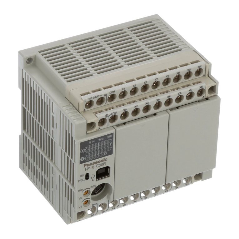
Panasonic Programmable Controllers FP-X Series User manual
Panasonic
Panasonic FP-XH Series User manual

Panasonic
Panasonic FP? Positioning Unit RTEX User manual
Panasonic
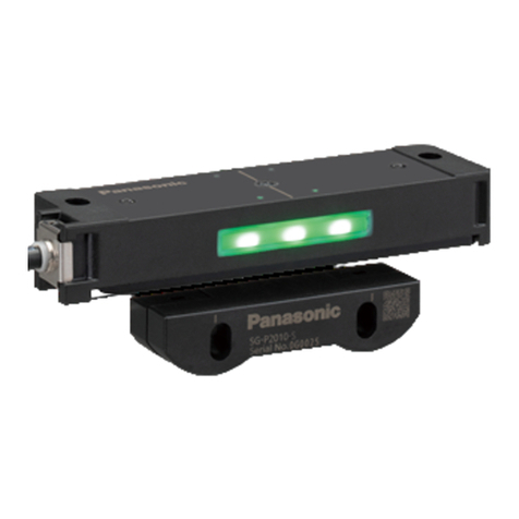
Panasonic SG-PK-M Series User manual
Panasonic
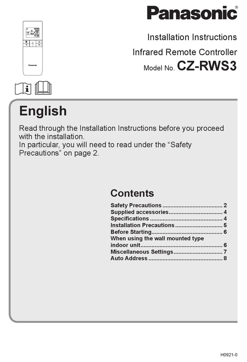
Panasonic CZ-RWS3 User manual

Panasonic
Panasonic FP2 Series User manual

Panasonic
Panasonic ACXF60-03410 User manual
Panasonic
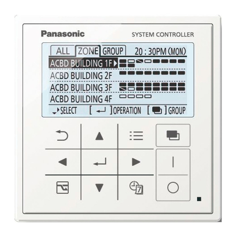
Panasonic CZ-64ESMC3 User manual

Panasonic
Panasonic AWRP605 - CCU & PAN/TILT CONTR User manual

Panasonic
Panasonic FP0H Series User manual
Panasonic
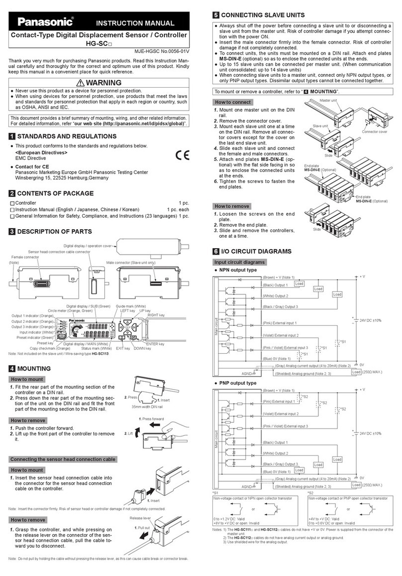
Panasonic HG-SC User manual
Panasonic
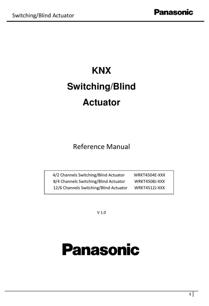
Panasonic WRKT4504E Series User manual

Panasonic
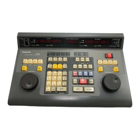
Panasonic MEWNET-F User manual
Panasonic
Panasonic AG-A850 User manual
Panasonic
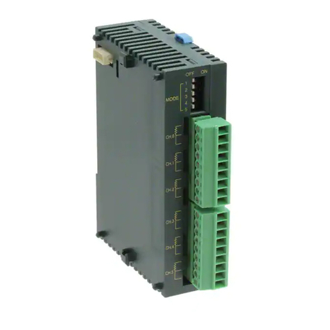
Panasonic FP0 Series User manual

Panasonic
Panasonic AW-RP60G User manual
Popular Controllers manuals by other brands

Digiplex
Digiplex DGP-848 Programming guide

YASKAWA
YASKAWA SGM series user manual

Sinope
Sinope Calypso RM3500ZB installation guide

Isimet
Isimet DLA Series Style 2 Installation, Operations, Start-up and Maintenance Instructions

LSIS
LSIS sv-ip5a user manual

Airflow
Airflow Uno hab Installation and operating instructions
